EP1979574B1 - Systeme de forage horizontal avec controle d'oscillation - Google Patents
Systeme de forage horizontal avec controle d'oscillation Download PDFInfo
- Publication number
- EP1979574B1 EP1979574B1 EP07762704.0A EP07762704A EP1979574B1 EP 1979574 B1 EP1979574 B1 EP 1979574B1 EP 07762704 A EP07762704 A EP 07762704A EP 1979574 B1 EP1979574 B1 EP 1979574B1
- Authority
- EP
- European Patent Office
- Prior art keywords
- motor
- torque
- drill string
- top drive
- automated controller
- Prior art date
- Legal status (The legal status is an assumption and is not a legal conclusion. Google has not performed a legal analysis and makes no representation as to the accuracy of the status listed.)
- Active
Links
Images


Classifications
-
- E—FIXED CONSTRUCTIONS
- E21—EARTH OR ROCK DRILLING; MINING
- E21B—EARTH OR ROCK DRILLING; OBTAINING OIL, GAS, WATER, SOLUBLE OR MELTABLE MATERIALS OR A SLURRY OF MINERALS FROM WELLS
- E21B44/00—Automatic control systems specially adapted for drilling operations, i.e. self-operating systems which function to carry out or modify a drilling operation without intervention of a human operator, e.g. computer-controlled drilling systems; Systems specially adapted for monitoring a plurality of drilling variables or conditions
- E21B44/02—Automatic control of the tool feed
- E21B44/04—Automatic control of the tool feed in response to the torque of the drive ; Measuring drilling torque
-
- E—FIXED CONSTRUCTIONS
- E21—EARTH OR ROCK DRILLING; MINING
- E21B—EARTH OR ROCK DRILLING; OBTAINING OIL, GAS, WATER, SOLUBLE OR MELTABLE MATERIALS OR A SLURRY OF MINERALS FROM WELLS
- E21B7/00—Special methods or apparatus for drilling
- E21B7/24—Drilling using vibrating or oscillating means, e.g. out-of-balance masses
-
- E—FIXED CONSTRUCTIONS
- E21—EARTH OR ROCK DRILLING; MINING
- E21B—EARTH OR ROCK DRILLING; OBTAINING OIL, GAS, WATER, SOLUBLE OR MELTABLE MATERIALS OR A SLURRY OF MINERALS FROM WELLS
- E21B3/00—Rotary drilling
- E21B3/02—Surface drives for rotary drilling
- E21B3/022—Top drives
-
- E—FIXED CONSTRUCTIONS
- E21—EARTH OR ROCK DRILLING; MINING
- E21B—EARTH OR ROCK DRILLING; OBTAINING OIL, GAS, WATER, SOLUBLE OR MELTABLE MATERIALS OR A SLURRY OF MINERALS FROM WELLS
- E21B7/00—Special methods or apparatus for drilling
- E21B7/04—Directional drilling
-
- E—FIXED CONSTRUCTIONS
- E21—EARTH OR ROCK DRILLING; MINING
- E21B—EARTH OR ROCK DRILLING; OBTAINING OIL, GAS, WATER, SOLUBLE OR MELTABLE MATERIALS OR A SLURRY OF MINERALS FROM WELLS
- E21B7/00—Special methods or apparatus for drilling
- E21B7/04—Directional drilling
- E21B7/046—Directional drilling horizontal drilling
Definitions
- This invention relates to a horizontal drilling system having an automated oscillation control system, and more particularly to an oscillation control system that reverses directions when a torque limit is exceeded and/or a drilling motor stalls.
- a well-known phenomenon in directional drilling is that hole friction dramatically increases if a horizontal drilling segment is required. That is, static friction (drag) occurs between the mud motor, drill collars, and drill pipe, and the casing and/or open hole. This high friction is caused by the drill string bearing against the bottom side of the hole. Increases in frictional forces are also frequently observed when the drill string tool joints are pushed laterally through the hole. This static friction can cause misleading indications of weight on bit, string weight and down-hole torque making automated control of the drilling process difficult, if not impossible.
- a drilling operator will vibrate or wiggle the drill string to cause it to slide within the hole.
- One way to vibrate the string is to rotate the drill string back and forth, a motion commonly referred to as oscillating the drill string. Oscillating the drill string causes the drill string to momentarily lift up in the hole thereby reducing the lateral friction.
- oscillating the drill string requires relatively rapid reversals of the drill string rotation.
- such an oscillation of the drill string is done manually by the drilling operator using standard operator controls found on many conventional top drive systems. To perform the oscillation, the operator lowers the motor torque limit and rotates the drill string in a clockwise direction at a low RPM until the drill string stalls or winds-up. The direction of rotation is then changed causing the drill string to unwind and then stall or wind-up in the opposite direction. This procedure is repeated by the operator until the frictional forces are reduced.
- TDCS top drive control systems
- VFD variable frequency drives
- the present invention is a horizontal drilling system that includes a top drive system having a motor that transmits a torque to a drill string to rotate the drill string.
- An automated controller is operably connected to the top drive to send at least one command signal to the top drive to initiate the rotation of the drill string.
- the top drive generates either a torque feedback signal indicating that a torque limit on the drill string is exceeded and/or a turn feedback signal indicating that the drill string is stalled.
- the controller receives the feedback signals and reverses the direction of the torque applied to the drill string when either the torque limit is exceeded or the drill string stalls.
- the top drive is an electric motor.
- the motor controller controls the speed of the electric motor by controlling the voltage applied, and regulates the amount of torque that can be applied by the electric motor by regulating the amount of current supplied to the electric motor.
- the electric motor is an AC motor.
- the controller regulates the torque and speed of the AC motor by regulating the frequency of the power supplied to the AC motor.
- the controller sets the direction of rotation of the electric motor, through an appropriate means, such as a directional switch for reversing the direction of rotation of the electrical motor.
- the torque feedback signal is determined by the electrical current flowing through the electric motor.
- the electric motor may also be mechanically coupled to a turn encoder for monitoring the amount of rotation of the electric motor.
- a rotational feedback signal is generated when the turn indicator detects that the electric motor has ceased to rotate, or has "stalled.”
- operational parameters may be input through a control station to set the programming instructions for the controller.
- the operator may input specific operating parameters for the controller to follow during an oscillation procedure, such as a torque limit for both the clockwise and counter-clockwise directions; and/or a rotation speed for both the clockwise and counter-clockwise directions.
- the torque limit may be the same in both the clockwise and counter-clockwise directions, or the torque limit may be different in the two directions.
- the controller includes a processor having a central processing unit (CPU), a memory cache, and a bus interface.
- the bus interface is operatively coupled via a system bus to a main memory and an input/output (I/O) interface control unit.
- the I/O interface control unit is operatively coupled via I/O local bus to a storage controller, and an I/O interface for transmission and reception of signals to external devices.
- the storage controller is operatively coupled to a storage device for storage of the programming instructions.
- the current invention is directed to a drill string oscillation procedure.
- embodiments of the present invention are directed to a horizontal drilling system having a controller for controlling an oscillation procedure of a drill string, whereby the drill string is rotated in a back and forth motion.
- the oscillation is controlled by reversing the direction of rotation of the drill string each time a torque limit is exceeded and/or when the drilling motor stalls.
- FIG. 1 is a schematic view of a horizontal drilling system 10 in accordance with an exemplary embodiment of the present invention.
- the horizontal drilling system 10 includes a top drive system 12.
- the top drive system 12 is vertically movable along vertical supports 14 of a derrick 16.
- the top drive system 12 includes a top drive motor 18, which imparts translational and rotational forces to a drill string 20.
- the top drive system 12 is connected to a pipe running tool 22, which in turn is connected to the drill string 20 to transfer the translational and rotational forces from the top drive system 12 to the drill string 20.
- the drill string 20 includes a horizontal segment 24 that produces a horizontal hole during a horizontal drilling operation.
- the top drive system 12 is operably connected to a controller 26.
- the controller 26 is used to control the top drive system 12 during both the drilling phases and the oscillation phases of a horizontal drilling procedure.
- the top drive system 12 receives command signals 28 from the controller 26 and responds to the command signals 28 by generating a torque and a rotational speed that are applied to the drill string 20.
- the top drive system 12 During operation, the top drive system 12 generates feedback signals 30 that are transmitted to the controller 26.
- the feedback signals 30 include a torque feed back signal and a rotational feed back signal.
- the controller 26 uses the feedback signals 30 to monitor the operation of the top drive system 12 during both drilling and oscillation procedures.
- the functions of the controller 26 are specified by a set of programming instructions 32 located in the controller 26.
- FIG. 3 is a block diagram of the horizontal drilling system 10 in accordance with an exemplary embodiment of the present invention.
- the horizontal drilling system 10 includes the top drive system 12 and the controller 26 as previously described.
- the horizontal drilling system 10 may include a motor controller 100 operatively connected to the top drive motor 18, which in one embodiment is an electric motor.
- the motor controller 100 receives high voltage/high current AC power 106 from an AC power supply 108, and transfers the AC power into regulated and controlled DC power for the electric motor 18.
- the motor controller 100 controls the speed of the electric motor 18 by controlling the voltage applied to the electric motor 18, and regulates the amount of torque that can be applied by the electric motor 18 by regulating the amount of current supplied to the electric motor 18.
- a DC motor is described above an AC motor could also be used.
- the controller would regulate the torque and speed of the AC motor by regulating the frequency of the power supplied to the AC motor.
- the command signals 28 as described above include a directional command signal 110, a torque limit signal 112 and a speed command signal 114.
- the motor controller 100 receives the directional command signal 110 transmitted by the controller 26 and responds to the directional command signal 110 by setting the direction of rotation of the electric motor 18.
- the electrical motor 18 may also have a directional switch 104 for reversing the direction of rotation of the electrical motor 18.
- the controller 26 of this embodiment may control the rotational direction of the drill string 20 by generating a directional command signal 110 and transmitting the directional command signal 110 to the motor controller 100.
- the motor controller 100 may also receive the torque limit signal 112 transmitted by the controller 26.
- the motor controller 100 of this embodiment uses the torque limit signal 112 to regulate the maximum amount of current supplied to the electric motor 18. Since the maximum amount of current supplied to the electric motor 18 determines the maximum amount of torque that can be applied by the electric motor 18 to the drill string 20, the controller 26 limits the amount of torque that can be applied by the electric motor 18 to the drill string 20.
- the motor controller 100 may also receive the speed command signal 114 transmitted by the system controller 26.
- the motor controller 100 of such an embodiment uses the speed command signal 114 to regulate the voltage/frequency supplied to the electric motor 18. Since the rotational speed of the electric motor 18 is determined by the voltage/frequency supplied to the electric motor 18, the controller 26 determines the rotational speed that the electric motor 18 imparts of the drill string 20.
- the motor controller 100 may also include a Silicon Controlled Rectifier (SCR) independently regulating the current and voltage (or frequency) supplied to the electric motor 18.
- SCR Silicon Controlled Rectifier
- the feedback signals 30 as described above include a torque feedback signal 116.
- the motor controller 100 generates the torque feedback signal 116 and transmits the signal to the system controller 26.
- the torque feedback signal 116 is proportional to the electrical current flowing through the electric motor 18 and is thus proportional to the torque applied by the electric motor 18.
- the controller 26 uses the torque feedback signal 116 to monitor the amount of torque applied to the drill string 20 by the electric motor 18.
- the electric motor 18 may also be mechanically coupled to a turn encoder 118.
- the turn encoder 118 monitors the amount of rotation of the electric motor 18, and sends a rotational feedback signal 120 to the controller 26 when the electric motor 18 has ceased to rotate, or has "stalled.”
- an operator inputs operational parameters into a control station (not shown) to set the programming instructions 32 of the controller 26.
- the operator may input specific operating parameters for the controller 26 to follow during an oscillation procedure, such as a torque limit for both the clockwise and counter-clockwise directions; and/or a rotation speed for both the clockwise and counter-clockwise directions.
- the torque limit may be the same in both the clockwise and counter-clockwise directions, or the torque limit may be different in the two directions.
- an oscillation procedure may be initiated.
- the controller 26 transmits command signals 28 to the top drive system 12 to initiate a rotation of the drill string 20 in an initial direction, for example the clockwise direction.
- the motor controller 100 monitors the torque applied to the drill string 20 and generates torque feedback signals 116 that are transmitted to the controller 26; and the turn encoder 118 monitors the amount of rotation of the drill string 20 and generates rotational feedback signals 120 that are transmitted to the controller 26.
- the torque feedback signal 116 transmits a signal signifying that the torque limit for the clockwise direction has been exceeded; or the rotational feedback signal 120 transmits a signal signifying that drill string 20 has ceased to rotate (i.e., the motor 18 has stalled), the direction of rotation of the drill string 20 is reversed to the counter-clockwise direction.
- the controller 26 transmits command signals 28 to the top drive system 12 to initiate a rotation of the drill string 20 in the counter-clockwise direction.
- the motor controller 100 monitors the torque applied to the drill string 20 and generates torque feedback signals 116 that are transmitted to the controller 26; and the turn encoder 118 monitors the amount of rotation of the drill string 20 and generates rotational feedback signals 120 that are transmitted to the controller 26.
- the torque feedback signal 116 transmits a signal signifying that the torque limit for the counter-clockwise direction has been exceeded; or the rotational feedback signal 120 transmits a signal signifying that drill string 20 has ceased to rotate, the direction of rotation of the drill string 20 is reversed back to the clockwise direction. This process may be repeated indefinitely.
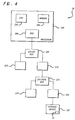
- FIG. 4 is a block diagram for the controller 26 in accordance with one embodiment of the present invention.
- the controller 26 includes a processor 200, having a central processing unit (CPU) 202, a memory cache 204, and a bus interface 206.
- the bus interface 206 is operatively coupled via a system bus 208 to a main memory 210 and an input/output (I/O) interface control unit 212.
- the I/O interface control unit 212 is operatively coupled via I/O local bus 214 to a storage controller 216, and an I/O interface 218 for transmission and reception of signals to external devices.
- the storage controller 216 is operatively coupled to a storage device 22 for storage of the programming instructions 32.
- the processor 200 retrieves the programming instructions 32 and stores them in the main memory 210.
- the processor 200 then executes the programming instructions 32 stored in the main memory 210.
- the processor 200 uses the programming instructions 32 to generate the previously described command signals 28 and transmits the command signals 28 via the external I/O device 218 to the top drive system 12.
- the top drive system 12 responds to the command signals 28 and generates the previously described feedback signals 30 that are transmitted back to the controller 26.
- the processor 200 receives the feedback signals 30 via the external I/O device 218.
- the processor 200 uses the feedback signals 30 and the programming instructions 32 to generate additional command signals, command signals 110, 112, and 114, for transmission to the top drive system 12 as previously described.
Landscapes
- Engineering & Computer Science (AREA)
- Geology (AREA)
- Life Sciences & Earth Sciences (AREA)
- Mining & Mineral Resources (AREA)
- Physics & Mathematics (AREA)
- Environmental & Geological Engineering (AREA)
- Fluid Mechanics (AREA)
- General Life Sciences & Earth Sciences (AREA)
- Geochemistry & Mineralogy (AREA)
- Mechanical Engineering (AREA)
- Earth Drilling (AREA)
- Drilling And Boring (AREA)
- Placing Or Removing Of Piles Or Sheet Piles, Or Accessories Thereof (AREA)
- Control Of Electric Motors In General (AREA)
Claims (18)
- Système de forage horizontal (10) comprenant :un système d'entraînement par le haut (12) comprenant un moteur (18) qui transmet un couple à un train de tiges de forage (20) pour faire tourner le train de tiges de forage ;une unité de commande automatisée (26) connectée de manière opérationnelle à l'entraînement par le haut pour envoyer au moins un signal d'ordre à l'entraînement par le haut pour initier le sens de la rotation du train de tiges de forage ;dans lequel l'entraînement par le haut génère au moins l'un d'un signal de rétroaction de couple indiquant qu'une limite de couple sur le train de tiges de forage est dépassée et d'un signal de rétroaction de tour indiquant que le train de tiges de forage a calé ; etdans lequel l'unité de commande reçoit le au moins un signal de rétroaction et inverse le sens du couple appliqué au train de tiges de forage lorsque soit la limite de couple est dépassée, soit le train de tiges de forage cale,caractérisé en ce que l'unité de commande automatisée est connectée de manière opérationnelle à l'entraînement par le haut pour envoyer au moins un signal d'ordre de vitesse et au moins un signal de limite de couple à l'entraînement par le haut pour commander la vitesse du moteur et le couple appliqué par le moteur.
- Système de forage horizontal (10) selon la revendication 1, dans lequel le moteur (18) est un moteur à courant continu et dans lequel l'unité de commande automatisée (26) est connectée de manière opérationnelle à une source d'alimentation (108) de telle sorte que l'unité de commande automatisée commande la vitesse du moteur électrique en ajustant la tension appliquée au moteur à courant continu, et régule le couple qui peut être appliqué par le moteur à courant continu en régulant le courant fourni au moteur à courant continu.
- Système de forage horizontal (10) selon la revendication 2, dans lequel l'unité de commande automatisée (26) génère le signal de rétroaction de couple en surveillant le courant fourni au moteur à courant continu (18).
- Système de forage horizontal (10) selon la revendication 1, dans lequel le moteur (18) est un moteur à courant alternatif et dans lequel l'unité de commande automatisée (26) est connectée de manière opérationnelle à une source d'alimentation (108) de telle sorte que l'unité de commande automatisée commande la vitesse et le couple du moteur à courant alternatif en régulant la fréquence de l'alimentation fournie au moteur à courant alternatif.
- Système de forage horizontal (10) selon la revendication 4, dans lequel l'unité de commande automatisée (26) génère le signal de rétroaction de couple en surveillant la fréquence de l'alimentation fournie au moteur à courant alternatif (18).
- Système de forage horizontal (10) selon la revendication 1, comprenant en outre un encodeur de tour connecté de manière opérationnelle à l'entraînement par le haut (12), l'encodeur de tour étant conçu pour surveiller la rotation de l'entraînement par le haut et générer le signal de rétroaction de tour.
- Système de forage horizontal (10) selon la revendication 1, comprenant en outre une station de commande connectée de manière opérationnelle à l'unité de commande automatisée (26) et conçue pour programmer l'unité de commande automatisée avec les informations de limite de couple et de limite de calage du train de tiges de forage (20).
- Système de forage horizontal (10) selon la revendication 1, dans lequel l'unité de commande automatisée (26) comprend en outre :un processeur (200) comportant une unité centrale (202) ;une mémoire cache (204) en communication de signal avec le processeur ;une interface bus (206) en communication de signal avec le processeur et l'entraînement par le haut (12) ; etdans lequel le processeur retrouve le au moins un signal d'ordre dans la mémoire cache et transmet le signal d'ordre par l'intermédiaire de l'interface bus à l'entraînement par le haut, et dans lequel l'entraînement par le haut génère les signaux de rétroaction de couple et de tour et transmet les signaux de rétroaction par l'intermédiaire de l'interface bus au processeur qui oeuvre sur les signaux de rétroaction en générant des signaux d'ordre additionnels dans un procédé de rétroaction continu.
- Système de forage horizontal (10) selon la revendication 1, dans lequel l'unité de commande automatisée (26) comprend en outre un jeu d'instructions de programmation qui dirige l'unité de commande automatisée pour qu'elle répète l'inversion du sens du couple appliqué au train de tiges de forage (20) à chaque fois soit que la limite de couple est dépassée, soit que le train de tiges de forage cale.
- Procédé de commande d'une opération de forage horizontal comprenant :le fait de donner un ordre à un système d'entraînement par le haut (12) comprenant un moteur (18) pour qu'il transmette un couple à un train de tiges de forage (20) pour faire tourner le train de tiges de forage dans un sens particulier ;la génération d'au moins l'un d'un signal de rétroaction de couple indiquant qu'une limite de couple sur le train de tiges de forage est dépassée et d'un signal de rétroaction de tour indiquant que le train de tiges de forage a calé ; etla communication du au moins un signal de rétroaction à une unité de commande automatisée (26) connectée de manière opérationnelle à l'entraînement par le haut, de telle sorte que l'unité de commande automatisée fournisse en sortie au moins un signal d'ordre directionnel à l'entraînement par le haut pour inverser le sens du couple appliqué au train de tiges de forage lorsque soit la limite de couple est dépassée, soit le train de tiges de forage cale,caractérisé en ce que le procédé comprend en outre l'étape de communication d'au moins un signal d'ordre de vitesse et d'au moins un signal de limite de couple à l'entraînement par le haut pour commander la vitesse du moteur et le couple appliqué par le moteur.
- Procédé selon la revendication 10, dans lequel le moteur (18) est un moteur à courant continu et dans lequel le procédé comprend en outre la commande de la vitesse du moteur électrique en ajustant la tension appliquée au moteur à courant continu, et la régulation du couple qui peut être appliqué par le moteur à courant continu par régulation du courant fourni au moteur à courant continu.
- Procédé selon la revendication 11, comprenant en outre la génération du signal de rétroaction de couple par surveillance du courant fourni au moteur à courant continu (18).
- Procédé selon la revendication 10, dans lequel le moteur est un moteur à courant alternatif (18) et dans lequel le procédé comprend en outre la commande de la vitesse et du couple du moteur à courant alternatif par régulation de la fréquence de l'alimentation fournie au moteur à courant alternatif.
- Procédé selon la revendication 13, comprenant en outre la génération du signal de rétroaction de couple par surveillance de la fréquence de l'alimentation fournie au moteur à courant alternatif (18).
- Procédé selon la revendication 10, comprenant en outre la surveillance de la rotation de l'entraînement par le haut et la génération du signal de rétroaction de tour.
- Procédé selon la revendication 10, comprenant en outre la préprogrammation de l'unité de commande automatisée (26) avec les informations de limite de couple et de limite de calage du train de tiges de forage (20).
- Procédé selon la revendication 10, comprenant en outre :le fait de retrouver au moins un signal d'ordre dans une mémoire cache (204) ;la transmission du signal d'ordre à l'entraînement par le haut (12) ;la transmission des signaux de rétroaction à l'unité de commande automatisée (26) ; etle fait d'oeuvrer sur les signaux de rétroaction pour générer des signaux d'ordre additionnels dans un procédé de rétroaction continu.
- Procédé selon la revendication 10, comprenant en outre la répétition du fait de donner un ordre à l'entraînement par le haut (12), de la génération du au moins un signal de rétroaction, de la communication du signal de rétroaction à l'unité de commande automatisée (26), et de l'inversion du sens du couple appliqué au train de tiges de forage (20) pour faire osciller le train de tiges de forage.
Applications Claiming Priority (2)
| Application Number | Priority Date | Filing Date | Title |
|---|---|---|---|
| US76269806P | 2006-01-27 | 2006-01-27 | |
| PCT/US2007/061066 WO2007090034A2 (fr) | 2006-01-27 | 2007-01-25 | Systeme de forage horizontal avec controle d'oscillation |
Publications (3)
| Publication Number | Publication Date |
|---|---|
| EP1979574A2 EP1979574A2 (fr) | 2008-10-15 |
| EP1979574A4 EP1979574A4 (fr) | 2015-04-29 |
| EP1979574B1 true EP1979574B1 (fr) | 2016-07-13 |
Family
ID=38328098
Family Applications (1)
| Application Number | Title | Priority Date | Filing Date |
|---|---|---|---|
| EP07762704.0A Active EP1979574B1 (fr) | 2006-01-27 | 2007-01-25 | Systeme de forage horizontal avec controle d'oscillation |
Country Status (6)
| Country | Link |
|---|---|
| US (1) | US7588099B2 (fr) |
| EP (1) | EP1979574B1 (fr) |
| CN (1) | CN101512098B (fr) |
| CA (1) | CA2636249C (fr) |
| NO (1) | NO339845B1 (fr) |
| WO (1) | WO2007090034A2 (fr) |
Families Citing this family (28)
| Publication number | Priority date | Publication date | Assignee | Title |
|---|---|---|---|---|
| US7500531B2 (en) * | 2005-10-03 | 2009-03-10 | Latourneau Technologies Drilling Systems, Inc. | Low speed AC motor for direct drive applications |
| DK2288783T3 (en) * | 2008-04-25 | 2016-05-17 | Weatherford Technology Holdings Llc | METHOD FOR CONTROLLING TORQUE APPLICABLE a tubular CONNECTION |
| BRPI0915004A2 (pt) * | 2008-06-13 | 2015-10-27 | Prad Res & Dev Ltd | aparelho de perfuração direcional e método para perfuração |
| USD631492S1 (en) * | 2008-08-13 | 2011-01-25 | Ronald William Yater | Module for drilling fluid pump system |
| US8534354B2 (en) * | 2010-03-05 | 2013-09-17 | Schlumberger Technology Corporation | Completion string deployment in a subterranean well |
| US8651175B2 (en) | 2011-01-14 | 2014-02-18 | Tesco Corporation | Top drive output torque measurement method |
| US8726743B2 (en) | 2011-06-22 | 2014-05-20 | Weatherford/Lamb, Inc. | Shoulder yielding detection during tubular makeup |
| US9593567B2 (en) | 2011-12-01 | 2017-03-14 | National Oilwell Varco, L.P. | Automated drilling system |
| US20130139614A1 (en) * | 2011-12-05 | 2013-06-06 | David C. Johnson | Portable torque work station and associated torquing method |
| US9249655B1 (en) * | 2012-05-31 | 2016-02-02 | Larry G. Keast | Control system for a top drive |
| US9290995B2 (en) | 2012-12-07 | 2016-03-22 | Canrig Drilling Technology Ltd. | Drill string oscillation methods |
| US9650880B2 (en) * | 2013-04-12 | 2017-05-16 | Tesco Corporation | Waveform anti-stick slip system and method |
| CA2915958C (fr) * | 2013-08-30 | 2017-11-07 | Halliburton Energy Services, Inc. | Rotation optimisee d'un train de tiges de forage pendant un mode glissant d'un forage directionnel |
| US9771788B2 (en) | 2014-03-25 | 2017-09-26 | Canrig Drilling Technology Ltd. | Stiction control |
| CA2942544C (fr) * | 2014-04-29 | 2020-06-30 | Halliburton Energy Services, Inc. | Controle de face d'outil d'un outil de fond de trou avec un frottement de train de tiges reduit |
| US10669816B2 (en) | 2015-11-10 | 2020-06-02 | Halliburton Energy Services, Inc. | Downhole component control assembly |
| US10100580B2 (en) * | 2016-04-06 | 2018-10-16 | Baker Hughes, A Ge Company, Llc | Lateral motion control of drill strings |
| WO2017205627A1 (fr) * | 2016-05-25 | 2017-11-30 | Lavalley Industries, Llc | Système de forage directionnel horizontal |
| US10422450B2 (en) | 2017-02-03 | 2019-09-24 | Weatherford Technology Holdings, Llc | Autonomous connection evaluation and automated shoulder detection for tubular makeup |
| US10378282B2 (en) | 2017-03-10 | 2019-08-13 | Nabors Drilling Technologies Usa, Inc. | Dynamic friction drill string oscillation systems and methods |
| US20190178072A1 (en) * | 2017-12-07 | 2019-06-13 | Tesco Corporation | Brake assembly for a tubular connection system |
| US10844675B2 (en) | 2018-12-21 | 2020-11-24 | Weatherford Technology Holdings, Llc | Autonomous connection makeup and evaluation |
| GB2576802B (en) * | 2019-03-20 | 2021-06-02 | Mhwirth As | Top drive and method of operating a top drive |
| US11549357B2 (en) | 2019-10-11 | 2023-01-10 | Pason Systems Corp. | Methods, systems and media for controlling a toolface of a downhole tool |
| CA3074312C (fr) | 2020-03-02 | 2020-08-11 | Pason Systems Corp. | Detection d`un blocage de moteur a boue |
| CA3095505C (fr) | 2020-10-06 | 2025-12-16 | Pason Systems Corp. | Methodes, systemes et support pour controler une face fonctionnelle d'un outil de fond de trou |
| US11692398B2 (en) | 2020-10-22 | 2023-07-04 | Terra Sonic International, LLC | Sonic-powered methods for horizontal directional drilling |
| CA3099282A1 (fr) | 2020-11-13 | 2022-05-13 | Pason Systems Corp. | Methodes, systemes et support lisible par ordinateur pour realiser un forage automatise d'un trou de forage |
Family Cites Families (25)
| Publication number | Priority date | Publication date | Assignee | Title |
|---|---|---|---|---|
| US2488107A (en) | 1945-08-17 | 1949-11-15 | Abegg & Reinhold Co | Drill pipe spinning device |
| US2863638A (en) | 1953-08-14 | 1958-12-09 | Bucyrus Erie Co | Rotary drill string apparatus |
| US3301334A (en) | 1964-06-25 | 1967-01-31 | Odgers Drilling Inc | Drill rig |
| US3747675A (en) | 1968-11-25 | 1973-07-24 | C Brown | Rotary drive connection for casing drilling string |
| US3708020A (en) | 1971-01-15 | 1973-01-02 | J Adamson | Continuous feed head drill assembly |
| US4100968A (en) | 1976-08-30 | 1978-07-18 | Charles George Delano | Technique for running casing |
| US4190119A (en) | 1977-12-12 | 1980-02-26 | Joy Manufacturing Company | Earth drilling apparatus |
| NO154578C (no) | 1984-01-25 | 1986-10-29 | Maritime Hydraulics As | Broennboreinnretning. |
| US4885963A (en) * | 1988-02-26 | 1989-12-12 | Mcc Corporation | Oscillating drive apparatus for working tool and working apparatus using the same |
| US4997042A (en) | 1990-01-03 | 1991-03-05 | Jordan Ronald A | Casing circulator and method |
| US5191939A (en) | 1990-01-03 | 1993-03-09 | Tam International | Casing circulator and method |
| US5294228A (en) | 1991-08-28 | 1994-03-15 | W-N Apache Corporation | Automatic sequencing system for earth drilling machine |
| US5297833A (en) | 1992-11-12 | 1994-03-29 | W-N Apache Corporation | Apparatus for gripping a down hole tubular for support and rotation |
| CN2168949Y (zh) * | 1993-05-27 | 1994-06-15 | 宁纯璞 | 一种钻机水平钻进装置 |
| US5584343A (en) | 1995-04-28 | 1996-12-17 | Davis-Lynch, Inc. | Method and apparatus for filling and circulating fluid in a wellbore during casing running operations |
| US5735348A (en) | 1996-10-04 | 1998-04-07 | Frank's International, Inc. | Method and multi-purpose apparatus for dispensing and circulating fluid in wellbore casing |
| US5918673A (en) | 1996-10-04 | 1999-07-06 | Frank's International, Inc. | Method and multi-purpose apparatus for dispensing and circulating fluid in wellbore casing |
| US6742596B2 (en) * | 2001-05-17 | 2004-06-01 | Weatherford/Lamb, Inc. | Apparatus and methods for tubular makeup interlock |
| US5971079A (en) | 1997-09-05 | 1999-10-26 | Mullins; Albert Augustus | Casing filling and circulating apparatus |
| EP1036250B1 (fr) | 1997-12-05 | 2002-10-02 | Deutsche Tiefbohr Aktiengesellschaft | Manipulation de sections de tube dans une installation de forage de sous-sol |
| US6142545A (en) | 1998-11-13 | 2000-11-07 | Bj Services Company | Casing pushdown and rotating tool |
| ATE328185T1 (de) | 1999-03-05 | 2006-06-15 | Varco Int | Ein- und ausbauvorrrichtung für rohre |
| US7059427B2 (en) | 2003-04-01 | 2006-06-13 | Noble Drilling Services Inc. | Automatic drilling system |
| US7096979B2 (en) * | 2003-05-10 | 2006-08-29 | Noble Drilling Services Inc. | Continuous on-bottom directional drilling method and system |
| CA2540619C (fr) * | 2003-10-09 | 2009-07-14 | Varco I/P, Inc. | Systeme de commande de vissage pour elements tubulaires |
-
2007
- 2007-01-25 EP EP07762704.0A patent/EP1979574B1/fr active Active
- 2007-01-25 US US11/627,162 patent/US7588099B2/en active Active
- 2007-01-25 CA CA2636249A patent/CA2636249C/fr active Active
- 2007-01-25 CN CN2007800034754A patent/CN101512098B/zh active Active
- 2007-01-25 WO PCT/US2007/061066 patent/WO2007090034A2/fr not_active Ceased
-
2008
- 2008-08-26 NO NO20083676A patent/NO339845B1/no unknown
Also Published As
| Publication number | Publication date |
|---|---|
| CA2636249C (fr) | 2011-06-14 |
| CN101512098A (zh) | 2009-08-19 |
| US7588099B2 (en) | 2009-09-15 |
| NO20083676L (no) | 2008-10-27 |
| CA2636249A1 (fr) | 2007-08-09 |
| US20070175662A1 (en) | 2007-08-02 |
| WO2007090034A2 (fr) | 2007-08-09 |
| CN101512098B (zh) | 2012-10-03 |
| EP1979574A4 (fr) | 2015-04-29 |
| WO2007090034A3 (fr) | 2009-05-07 |
| EP1979574A2 (fr) | 2008-10-15 |
| NO339845B1 (no) | 2017-02-06 |
Similar Documents
| Publication | Publication Date | Title |
|---|---|---|
| EP1979574B1 (fr) | Systeme de forage horizontal avec controle d'oscillation | |
| EP1676015B1 (fr) | Systeme de commande de vissage pour elements tubulaires | |
| EP2480744B1 (fr) | Systèmes et procédés d'amélioration de rendement de forage | |
| CA2891740C (fr) | Procedes d'oscillation de train de tiges de forage | |
| US20190187012A1 (en) | Method for measuring surface torque oscillation performance index | |
| CN101755102B (zh) | 具有压力微分控制的恒定模式自动钻井 | |
| WO2016102381A1 (fr) | Système de commande de surveillance et procédé d'automatisation d'opérations de forage | |
| US11525321B2 (en) | Controlling release of torsional energy from a drill string | |
| US11486245B2 (en) | Micro-rotating drilling method in directional drilling, computer device and readable storage medium | |
| US12012841B2 (en) | Automatically detecting and unwinding accumulated drill string torque | |
| Wiesenborn et al. | Automated wireline milling system | |
| CN106598091B (zh) | 一种消除钻柱粘滑振动的控制系统及方法 | |
| CN118292514B (zh) | 高频锤反馈控制装置、方法、系统及施工设备 | |
| US11916507B2 (en) | Motor angular position control | |
| CN204357349U (zh) | 一种基于装置有软扭矩顶驱电机的角度精确定位系统 | |
| RU58174U1 (ru) | Автоматизированная система управления режимом бурения | |
| CN103726827A (zh) | 钻杆运动控制方法、装置及系统 | |
| EP4532883A1 (fr) | Entraînement de train de tiges de forage pour communiquer une puissance de rotation à une extrémité supérieure du train de tiges de forage pour forer un puits de forage | |
| US20140352996A1 (en) | Apparatus and method for transferring electrical power to a rotating shaft | |
| JP2007521424A (ja) | チューブラーのメイクアップの制御システム | |
| JP2006168292A (ja) | 油圧コアドリル等の自動送り装置及びその制御方法 | |
| BR112019006277B1 (pt) | Sistema e método para operar uma máquina de corte |
Legal Events
| Date | Code | Title | Description |
|---|---|---|---|
| PUAI | Public reference made under article 153(3) epc to a published international application that has entered the european phase |
Free format text: ORIGINAL CODE: 0009012 |
|
| 17P | Request for examination filed |
Effective date: 20080821 |
|
| AK | Designated contracting states |
Kind code of ref document: A2 Designated state(s): AT BE BG CH CY CZ DE DK EE ES FI FR GB GR HU IE IS IT LI LT LU LV MC NL PL PT RO SE SI SK TR |
|
| AX | Request for extension of the european patent |
Extension state: AL BA HR MK RS |
|
| R17D | Deferred search report published (corrected) |
Effective date: 20090507 |
|
| RIC1 | Information provided on ipc code assigned before grant |
Ipc: E21B 19/16 20060101AFI20090813BHEP |
|
| DAX | Request for extension of the european patent (deleted) | ||
| RBV | Designated contracting states (corrected) |
Designated state(s): DE GB NL |
|
| REG | Reference to a national code |
Ref country code: DE Ref legal event code: R079 Ref document number: 602007046991 Country of ref document: DE Free format text: PREVIOUS MAIN CLASS: E21B0044000000 Ipc: E21B0044040000 |
|
| A4 | Supplementary search report drawn up and despatched |
Effective date: 20150401 |
|
| RIC1 | Information provided on ipc code assigned before grant |
Ipc: E21B 7/04 20060101ALI20150326BHEP Ipc: E21B 44/04 20060101AFI20150326BHEP Ipc: E21B 7/24 20060101ALI20150326BHEP |
|
| GRAP | Despatch of communication of intention to grant a patent |
Free format text: ORIGINAL CODE: EPIDOSNIGR1 |
|
| INTG | Intention to grant announced |
Effective date: 20160204 |
|
| GRAS | Grant fee paid |
Free format text: ORIGINAL CODE: EPIDOSNIGR3 |
|
| GRAA | (expected) grant |
Free format text: ORIGINAL CODE: 0009210 |
|
| AK | Designated contracting states |
Kind code of ref document: B1 Designated state(s): DE GB NL |
|
| REG | Reference to a national code |
Ref country code: GB Ref legal event code: FG4D |
|
| REG | Reference to a national code |
Ref country code: DE Ref legal event code: R096 Ref document number: 602007046991 Country of ref document: DE |
|
| REG | Reference to a national code |
Ref country code: NL Ref legal event code: FP |
|
| REG | Reference to a national code |
Ref country code: DE Ref legal event code: R097 Ref document number: 602007046991 Country of ref document: DE |
|
| PLBE | No opposition filed within time limit |
Free format text: ORIGINAL CODE: 0009261 |
|
| STAA | Information on the status of an ep patent application or granted ep patent |
Free format text: STATUS: NO OPPOSITION FILED WITHIN TIME LIMIT |
|
| 26N | No opposition filed |
Effective date: 20170418 |
|
| PGFP | Annual fee paid to national office [announced via postgrant information from national office to epo] |
Ref country code: GB Payment date: 20251204 Year of fee payment: 20 |
|
| PGFP | Annual fee paid to national office [announced via postgrant information from national office to epo] |
Ref country code: NL Payment date: 20251215 Year of fee payment: 20 |
|
| PGFP | Annual fee paid to national office [announced via postgrant information from national office to epo] |
Ref country code: DE Payment date: 20251203 Year of fee payment: 20 |