EP1979792B1 - Procede pour le reglage d'une valeur reelle pour une grandeur caracterisant une position d'un element de reglage final, produit de programme informatique et programme informatique - Google Patents
Procede pour le reglage d'une valeur reelle pour une grandeur caracterisant une position d'un element de reglage final, produit de programme informatique et programme informatique Download PDFInfo
- Publication number
- EP1979792B1 EP1979792B1 EP07704045A EP07704045A EP1979792B1 EP 1979792 B1 EP1979792 B1 EP 1979792B1 EP 07704045 A EP07704045 A EP 07704045A EP 07704045 A EP07704045 A EP 07704045A EP 1979792 B1 EP1979792 B1 EP 1979792B1
- Authority
- EP
- European Patent Office
- Prior art keywords
- transfer function
- profile
- straight line
- controller
- computer program
- Prior art date
- Legal status (The legal status is an assumption and is not a legal conclusion. Google has not performed a legal analysis and makes no representation as to the accuracy of the status listed.)
- Not-in-force
Links
Images

Classifications
-
- G—PHYSICS
- G05—CONTROLLING; REGULATING
- G05B—CONTROL OR REGULATING SYSTEMS IN GENERAL; FUNCTIONAL ELEMENTS OF SUCH SYSTEMS; MONITORING OR TESTING ARRANGEMENTS FOR SUCH SYSTEMS OR ELEMENTS
- G05B11/00—Automatic controllers
- G05B11/01—Automatic controllers electric
- G05B11/011—Automatic controllers electric details of the correcting means
-
- G—PHYSICS
- G05—CONTROLLING; REGULATING
- G05B—CONTROL OR REGULATING SYSTEMS IN GENERAL; FUNCTIONAL ELEMENTS OF SUCH SYSTEMS; MONITORING OR TESTING ARRANGEMENTS FOR SUCH SYSTEMS OR ELEMENTS
- G05B19/00—Program-control systems
- G05B19/02—Program-control systems electric
- G05B19/18—Numerical control [NC], i.e. automatically operating machines, in particular machine tools, e.g. in a manufacturing environment, so as to execute positioning, movement or co-ordinated operations by means of program data in numerical form
- G05B19/19—Numerical control [NC], i.e. automatically operating machines, in particular machine tools, e.g. in a manufacturing environment, so as to execute positioning, movement or co-ordinated operations by means of program data in numerical form characterised by positioning or contouring control systems, e.g. to control position from one programmed point to another or to control movement along a programmed continuous path
-
- G—PHYSICS
- G05—CONTROLLING; REGULATING
- G05B—CONTROL OR REGULATING SYSTEMS IN GENERAL; FUNCTIONAL ELEMENTS OF SUCH SYSTEMS; MONITORING OR TESTING ARRANGEMENTS FOR SUCH SYSTEMS OR ELEMENTS
- G05B2219/00—Program-control systems
- G05B2219/30—Nc systems
- G05B2219/37—Measurements
- G05B2219/37612—Transfer function, kinematic identification, parameter estimation, response
Definitions
- the invention is based on a method for regulating an actual value for a variable characterizing a position of an actuator, a computer program product, a computer program and a record carrier according to the preamble of the independent claims.
- a method for controlling an actual value for a variable characterizing a position of an actuator by means of a controller to a desired value is already well known. It is also known to transform a predetermined time profile of the setpoint into a desired time characteristic of the actual value, wherein a transfer function in the frequency domain for the transformation of the predetermined time profile of the setpoint formed in the desired time course of the actual value and approximated by one or more factors becomes. These factors are usually proportional-time-members (PT) of integer order, i. H. with integer exponents. From the publication "La commande CRONE, du scalaire au multivariable, A. Oustaloup and B. Mathieu, Hermes, 1999” is also known the use of CRONE controllers that exploit the properties of a new mathematical operator that does not support the concept of derivatives generalized integer order.
- PT proportional-time-members
- the inventive method for controlling an actual value for a characteristic of a position actuator size, computer program product according to the invention, the computer program according to the invention and the recording medium according to the invention with the features of the independent claims have the advantage that for at least one of the factors of the transfer function for transformation the predetermined time profile of the setpoint in the desired time course of the actual value, a non-integer exponent is selected.
- the described formation or modeling of the transfer function in the frequency domain allows for excellent control performance in the form of an optimal compromise between bandwidth, stability, accuracy and robustness of the control due to the non-integer exponent of the at least one of the factors.
- the transfer function has a linear structure that does not require adapting the controller parameters depending on maps and operating conditions.
- the time required to calibrate the control is very short due to the already mentioned reduced number of parameters and the linear characteristics of the transfer function, which allows the use of linear control theory during calibration, thus avoiding repeated and time-consuming calibration tests.
- a profile of the first transfer function in the frequency domain is determined when the first transfer function determined in this way is approximated by one or more straight line pieces for which a respective factor of the first transfer function is determined, at least one of the factors has a non-integer exponent.
- the desired first transfer function in the frequency domain can be mapped in a particularly simple and inexpensive manner in the form of a mathematical function.
- the course of the desired first transfer function in the frequency domain can first be determined numerically in a simple manner.
- a CRONE controller is used as controller.
- the desired first transfer function with the at least one factor and its non-integer exponent can be implemented particularly easily, because the CRONE controller also allows the use of a transfer function with at least one factor whose exponent is not an integer.
- FIG. 1 is a functional diagram for controlling the position of an electronic actuator 1 of an internal combustion engine shown.
- the electronic actuator 1 is used for example for controlling the internal combustion engine and may for example be a throttle valve, an exhaust gas recirculation valve, a wastegate valve or an actuator for varying the geometry of a turbine of an exhaust gas turbocharger.
- the electronic actuator 1 comprises an electric torque source 4, which is designed for example as a DC motor.
- the electric torque source 4 is connected to a power converter 3 which provides the electric power source 4 with the required electric power according to an input control signal u.
- the power converter 3 can For example, be designed as a variable voltage or current source and be designed in particular for the delivery of a pulse width modulated voltage or current signal. Accordingly, the input control signal u corresponds to a voltage value U, a current value I or a duty ratio ⁇ .
- the electric torque source 4 drives a load 6 in a rotational or in a translational movement via a kinematic transmission element 5.
- the load 6 may be, for example, the flap of a throttle or an exhaust gas recirculation valve.
- the kinematic transmission member 5 typically includes transmission elements having possible non-linear characteristics such as stiction, sliding friction and / or Coulomb friction or variable gear ratios.
- the kinematic transmission member 5 may also include a combination of mechanical springs which force the load 6 to return to a predetermined position when no torque is given by the electric torque source.
- a bearing check 7 is connected to the load 6 and determines an actual value Y for the position of the load 6.
- the electronic actuator 1 is connected to a control device 2, which is designed for example as a microprocessor-based drive train control.
- the control device 2 receives the actual value Y from the bearing feedback 7 and outputs the control signal u to the power converter 3.
- the control device 2 carries out a position control algorithm 8 which periodically determines new values of the control signal u as a function of the received actual value y and a predetermined desired value y ref .
- the predefined setpoint value y ref is provided, for example, by an air system management algorithm 9 in a manner known to the person skilled in the art, for example as a function of an accelerator pedal position.
- the air system management algorithm 9 is according to the example FIG. 1 also implemented in the control device 2.
- the position control algorithm 8 and the air system management algorithm 9 can be implemented in software and / or hardware in the control device 2 or in separate control devices. Further input and output variables of the control device 2 are in FIG. 1 designated by the reference numerals 25 and 30, respectively.
- the input variables 25 include, for example, the abovementioned accelerator pedal position and further operating variables of the internal combustion engine, such as the engine speed and the engine load, for example, depending on an air mass flow supplied to the internal combustion engine or a Saugrohr horres.
- the output variables 30 of the control device 2 include, for example, quantities for setting an ignition timing in the case of a gasoline engine or the control of other valves or electrical actuators, such as exhaust gas recirculation valve, Wastgate valve, injector, etc., which are realized according to the described construction of the electric actuator 1 can.
- the Positionregelagorithmus 8 includes a pre-filter 12, which is supplied to a predetermined time profile of the setpoint value y ref .
- the pre-filter 12 filters the predetermined time profile of the setpoint value y ref and outputs a filtered time profile of the setpoint value y filter at its output.
- a control deviation ⁇ is formed in a connection point 35 by subtracting the time profile of the actual value y from the filtered time profile of the setpoint value y filter .
- the control deviation ⁇ is then fed to a controller 11 which, depending on the control deviation ⁇ , determines the control signal u in the sense of minimizing the control deviation ⁇ and delivers it to the electronic actuator 1.
- the controller 11 can be used, for example, as P controller, I controller, D controller, PI controller, as PD controller, as PID controller or in a particularly advantageous manner as CRONE controller according to the publication "La commande CRONE, du scalaire au Multivariable, A. Oustaloup and B. Mathieu, Hermes, 1991, and in the latter case have at least one factor of the transfer function in the frequency domain with non-integer exponent is.
- the required course of the desired first transfer function in the frequency domain can be determined, for example, with the aid of numerical approximation methods, that is, not mathematically analytical.
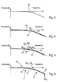
- the course the desired first transfer function in the form of a Bode diagram as in FIG. 3 be determined exemplified.
- the amplitude of the desired first transfer function is plotted against the frequency and indicated by the reference numeral 40.
- the curve of the amplitude of the desired first transfer function over the frequency determined numerically in this example by means of the Bode diagram is approximated by a mathematical function. So far, for example, this has been done using a PT1 element (proportional-time element of the first order) as described in US Pat FIG. 4 is shown.
- the course is 40 by a first straight line piece 45 with the slope 0 and a second straight line piece 50 with a negative slope as in FIG. 4 shown approximated.
- s denotes the Laplace variable in the frequency domain and ⁇ l 1 the lower limit frequency at which the second straight line 50 begins in the frequency domain.
- a better approximation of the curve 40 is obtained, if one according to FIG. 5 mathematically analytically approximates the desired transfer function by the product of the transfer functions of several PT elements of the nth order, where n is an integer.
- the course 40 is approximated by three straight line sections with the gradient 0 and three straight line sections with a different negative gradient. Spotted is in FIG. 5 according to FIG. 4 performed approximation with the PT1 element shown.
- the course 40 can be better approximated than by using only the PT1 element FIG. 4 , A first straight line with negative Slope is in FIG.
- the first straight line piece 55 has a negative slope with the amount of 20 dB / decade in logarithmic representation.
- the second straight line piece 60 has a negative slope of the order of 40 dB / decade in a logarithmic representation.
- the third line piece 65 has a negative slope with the amount of 20 dB / decade in logarithmic representation.
- n k is the integer order of the respective factor.
- ⁇ l 1 the lower limit frequency of the first straight line 55 and ⁇ h 1 the upper limit frequency of the first straight line piece 55.
- ⁇ l 2 is the lower limit frequency of the second straight line 60 and ⁇ h 2 is the upper limit frequency of the second straight line piece 60.
- ⁇ l 3 is the lower limit frequency of the third straight line 65 and ⁇ h 3 is the upper limit frequency of the third straight line piece 65.
- ⁇ l 1 is the lower limit frequency of a first straight line piece 15 with negative slope for approximation of the course 40 according to FIG. 6 and ⁇ h 1 is the upper limit frequency of the first straight line piece 15.
- ⁇ l 2 is the lower limit frequency of a second straight line piece 20 with negative slope for approximation of the course 40 according to FIG. 6 and ⁇ h 2 is the upper limit frequency of the second straight line piece 20.
- the factor with the exponent n 1 in equation (3) is associated with the first straight line 15 and the factor with the exponent n 2 is associated with the second straight line 20.
- n k 0.5 at an amount of the negative slope of the associated straight line piece of 10 dB / decade.
- the exponent n k is equal to 0.25 at an amount of the negative slope of the associated straight line of 5 dB / decade.
- the exponent n k is equal to 0.75 for an amount of negative Slope of associated straight line of 15 dB / decade.
- H PT fractional is thus the mathematically analytical approximation of the desired first transfer function between the predetermined time profile of the setpoint value y ref and the desired time profile of the actual value y.
- the function H PT fractional is significantly closer to the desired curve 40 and requires significantly fewer parameters, at least in comparison to the function H PTn .
- the control system shown must have the parameters n k , ⁇ l k and / or ⁇ h k however, be further modified.
- These physical boundary conditions may include, for example, limit values for the maximum permissible voltage or the maximum permissible current for driving the electric torque source 4.
- n k , ⁇ l k and / or ⁇ h k optionally be further modified depending on the physical behavior of the electronic actuator 1 in the frequency domain, in particular to meet the physical constraints of the control system in terms of performance and robustness can.
- the mathematically analytically obtained transfer function H PT fractional according to equation (3) comprises at least one factor with non-integer exponents.
- the transfer function of the prefilter 12 is determined, which is also referred to below as the second transfer function. It transforms the predetermined time profile of the setpoint value y ref into the desired filtered time profile of the setpoint value y filter .
- T is the transfer function of the regulator 11 and the electronic actuator 1 in the frequency domain and is determined in a manner known to those skilled in the art.
- F fractional according to equation (4) the transfer function of the prefilter 12 in the frequency domain.
- the second transfer function F fractional is transformed back into the time domain in a manner known to those skilled in the art and transformed into a time-discrete transfer function F z (z) in the time domain according to the following form for implementation in a control unit program of the control device 2:
- z is the discrete time variable and a k , b k , N den , N num are the parameters of the time-discrete transfer function F z (z) resulting from the described transformation.
- the described inverse transformation from the second transfer function F fractional of the equation (4) into the discrete-time transfer function F z (z) according to equation (5) is not always mathematically analytically possible, so that, if necessary, an approximate solution for this inverse transformation must be found known in the art using the Bode diagram in the frequency domain can be performed.
- the second transfer function F fractional generally results according to equation (4) with at least one factor with non-integer exponent.
- the controller is designed as a CRONE controller whose transfer function, referred to as the third transfer function, likewise has at least one factor with non-integer exponent, then the control system relaxes FIG. 2 with maximum number of degrees of freedom with minimum number of parameters in terms of maximum bandwidth, stability, accuracy and robustness optimally set with the least possible time and storage space.
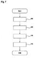
- FIG. 7 a flow chart for an exemplary sequence of the method according to the invention is shown.
- a program point 100 in the manner described the course of the desired first transfer function in the frequency domain, for example by means of a Bode diagram and numerical approximation with the proviso of the transformation of the predetermined time course of the setpoint y ref in the desired time course of the actual value y determined.
- a branch is made to a program point 105.
- the second transfer function F fractional is determined from the transfer function H PT fractional and the transfer function T of the controller 11 and of the electric actuator 1 determined in the manner known to those skilled in the art according to equation (4). Subsequently, a branch is made to a program point 115.
- the second transfer function F fractional of equation (4) is transformed in the manner described by approximation using the Bode diagram in the frequency domain in the discrete-time transfer function F z (z) according to equation (5), which then in a ECU program of the control device 2 software and / or hardware implemented.
- the sequence of the method according to the invention can be carried out, for example, program-code-controlled by means of a computer program which recalculates all steps of the flowchart FIG. 7 performs when the computer program is executed in a computer such as a microprocessor of the control device 2.
- the program code can also be stored on a machine-readable carrier or recording medium and thus form a computer program product.
- the machine-readable carrier or recording medium can be fixedly arranged in the control device 2 or fed by means of a drive of the control device for reading and performing all steps of the program code from the outside.
- the method according to the invention can be used, for example, in the control unit of an internal combustion engine, for example a gasoline engine or a diesel engine.
Landscapes
- Engineering & Computer Science (AREA)
- Physics & Mathematics (AREA)
- General Physics & Mathematics (AREA)
- Automation & Control Theory (AREA)
- Human Computer Interaction (AREA)
- Manufacturing & Machinery (AREA)
- Feedback Control In General (AREA)
Claims (8)
- Procédé pour la création d'une première fonction de transfert pour la transformation de l'évolution temporelle définie d'une valeur de consigne en une évolution temporelle souhaitée d'une valeur réelle en utilisant un régulateur (11) pour régler la valeur réelle d'une grandeur caractérisant une position d'un actionneur (1) sur la valeur de consigne, dans lequel on crée la première fonction de transfert dans le domaine fréquentiel pour la transformation de l'évolution temporelle définie de la valeur de consigne en l'évolution temporelle souhaitée de la valeur réelle et on approxime au moyen d'un ou plusieurs facteurs, notamment des éléments temporels proportionnels, dans lequel on choisit un exposant non entier pour au moins un des facteurs et on transforme l'évolution définie de la valeur de consigne en évolution souhaitée de la valeur de consigne au moyen d'un filtre (12), caractérisé en ce qu'on crée une deuxième fonction de transfert avec au moins un facteur dont l'exposant n'est pas entier comme fonction de transfert du filtre (12) au moyen de la division de la première fonction de transfert approximée par la fonction de transfert du régulateur (11) et de l'actionneur (1).
- Procédé selon la revendication 1, caractérisé en ce qu'on définit une évolution de la première fonction de transfert dans le domaine fréquentiel, en ce que la première fonction de transfert ainsi définie est approximée au moyen d'une ou de plusieurs parties droites (15, 20) en représentation logarithmique, pour lesquelles on définit un facteur représentant respectivement la partie droite (15, 20) de la première fonction de transfert, un au moins des facteurs comportant un exposant non entier.
- Procédé selon la revendication 2, caractérisé en ce que l'évolution de la première fonction de transfert est définie numériquement dans le domaine fréquentiel.
- Procédé selon la revendication 2 ou 3, caractérisé en ce que l'évolution de la première fonction de transfert est définie sous la forme d'un diagramme de Bode.
- Procédé selon une des revendications précédentes, caractérisé en ce qu'on met en oeuvre un régulateur CRONE comme régulateur (11).
- Procédé selon la revendication 5, caractérisé en ce qu'on choisit une troisième fonction de transfert comme fonction de transfert du régulateur CRONE (11) avec au moins un facteur comportant un exposant non entier.
- Produit logiciel pour ordinateur avec un code de programme stocké sur un support lisible par la machine, pour l'exécution du procédé selon une des revendications 1 à 6 lorsqu'on exécute le logiciel dans un ordinateur.
- Produit logiciel pour ordinateur avec un code de programme pour l'exécution de toutes les étapes selon une des revendications 1 à 6 lorsqu'on exécute le logiciel dans un ordinateur.
Applications Claiming Priority (2)
| Application Number | Priority Date | Filing Date | Title |
|---|---|---|---|
| DE102006003251A DE102006003251A1 (de) | 2006-01-24 | 2006-01-24 | Verfahren zum Regeln eines Istwertes für eine eine Position eines Stellgliedes charakterisierende Größe, Computerprogramm-Produkt, Computerprogramm und Aufzeichnungsträger |
| PCT/EP2007/050577 WO2007085578A1 (fr) | 2006-01-24 | 2007-01-22 | Procede pour le reglage d'une valeur reelle pour une grandeur caracterisant une position d'un element de reglage final, produit de programme informatique, programme informatique et support d'enregistrement |
Publications (2)
| Publication Number | Publication Date |
|---|---|
| EP1979792A1 EP1979792A1 (fr) | 2008-10-15 |
| EP1979792B1 true EP1979792B1 (fr) | 2010-03-31 |
Family
ID=37943853
Family Applications (1)
| Application Number | Title | Priority Date | Filing Date |
|---|---|---|---|
| EP07704045A Not-in-force EP1979792B1 (fr) | 2006-01-24 | 2007-01-22 | Procede pour le reglage d'une valeur reelle pour une grandeur caracterisant une position d'un element de reglage final, produit de programme informatique et programme informatique |
Country Status (5)
| Country | Link |
|---|---|
| US (1) | US20100191789A1 (fr) |
| EP (1) | EP1979792B1 (fr) |
| JP (1) | JP2009524172A (fr) |
| DE (2) | DE102006003251A1 (fr) |
| WO (1) | WO2007085578A1 (fr) |
Families Citing this family (1)
| Publication number | Priority date | Publication date | Assignee | Title |
|---|---|---|---|---|
| RU174480U1 (ru) * | 2015-07-06 | 2017-10-16 | Михаил Леонидович Лазаренко | Регулятор |
Family Cites Families (8)
| Publication number | Priority date | Publication date | Assignee | Title |
|---|---|---|---|---|
| JP2691528B2 (ja) * | 1986-03-14 | 1997-12-17 | 東芝機械株式会社 | 完全追従形サーボシステム |
| JPH0354602A (ja) * | 1989-07-22 | 1991-03-08 | Nobuo Yamamoto | 制御系の時間差比較2自由度制御方法及び装置 |
| JP3138069B2 (ja) * | 1992-07-29 | 2001-02-26 | 三洋電機株式会社 | 電子部品装着装置における位置制御装置 |
| US5371670A (en) * | 1993-02-01 | 1994-12-06 | The United States Of America As Represented By The Administrator Of The National Aeronautics And Space Administration | Three-parameter tunable tilt-integral-derivative (TID) controller |
| DE10060125A1 (de) * | 2000-12-04 | 2002-06-13 | Siemens Ag | Verfahren zur Regelung eines verzögerungsbehafteten Prozesses mit Ausgleich sowie Regeleinrichtung zur Durchführung des Verfahrens |
| DE60018587D1 (de) * | 2000-12-27 | 2005-04-14 | St Microelectronics Srl | Dynamische Systeme nicht geradzahliger Ordnung |
| US6856181B1 (en) * | 2002-12-30 | 2005-02-15 | Cypress Semiconductor Corporation | Stability robustness using a non-integer order filter in a circuit |
| US7599752B2 (en) * | 2005-05-17 | 2009-10-06 | Utah State University | Tuning methods for fractional-order controllers |
-
2006
- 2006-01-24 DE DE102006003251A patent/DE102006003251A1/de not_active Withdrawn
-
2007
- 2007-01-22 WO PCT/EP2007/050577 patent/WO2007085578A1/fr not_active Ceased
- 2007-01-22 DE DE502007003300T patent/DE502007003300D1/de active Active
- 2007-01-22 US US12/087,803 patent/US20100191789A1/en not_active Abandoned
- 2007-01-22 EP EP07704045A patent/EP1979792B1/fr not_active Not-in-force
- 2007-01-22 JP JP2008551769A patent/JP2009524172A/ja not_active Withdrawn
Also Published As
| Publication number | Publication date |
|---|---|
| DE102006003251A1 (de) | 2007-07-26 |
| DE502007003300D1 (de) | 2010-05-12 |
| US20100191789A1 (en) | 2010-07-29 |
| WO2007085578A1 (fr) | 2007-08-02 |
| JP2009524172A (ja) | 2009-06-25 |
| EP1979792A1 (fr) | 2008-10-15 |
Similar Documents
| Publication | Publication Date | Title |
|---|---|---|
| DE2715408C2 (de) | Verfahren zum Betrieb und Regeleinrichtung für eine Brennkraftmaschine zum Konstanthalten wählbarer Drehzahlen | |
| EP3997527B1 (fr) | Planification de trajectoires en temps réel destinée à des pompes de pistons axiaux en construction à plateau orientable avec prise en compte systématique de limitations de système | |
| EP1465034B1 (fr) | Procédé de contrôle de la commande de vitesse pour limiter les à-coups d'un élément mobile d'une machine-outil à commande numérique | |
| WO1998024008A1 (fr) | Circuit de reglage comprenant un regulateur numerique pour reguler le courant d'entree d'un acteur electrique a l'aide de la modulation d'impulsions en largeur | |
| EP0914631B1 (fr) | Regulateur proportionnel-integral-differentiel (pid) a integrateur protege contre la saturation lors d'une variation rapide de la grandeur de reference | |
| DE3437324A1 (de) | Verfahren und vorrichtung zur regelung der leerlaufdrehzahl bei brennkraftmaschinen | |
| DE3344415A1 (de) | Fahrgeschwindigkeitsregler fuer kraftfahrzeuge | |
| EP3594480A1 (fr) | Procédé de commande d'un syst?me de charge | |
| EP1347165B1 (fr) | Procédé et dispositif de commande du dosage de carburant pour un moteur à combustion interne | |
| EP1979792B1 (fr) | Procede pour le reglage d'une valeur reelle pour une grandeur caracterisant une position d'un element de reglage final, produit de programme informatique et programme informatique | |
| DE3416812A1 (de) | Verfahren zur regelung von prozessgroessen in motorfahrzeugen | |
| DE102008005154B4 (de) | Verfahren und Vorrichtung zur Überwachung einer Motorsteuereinheit | |
| DE4303560B4 (de) | Verfahren und Vorrichtung zur Steuerung einer Verstelleinrichtung | |
| EP0707718B1 (fr) | Systeme de regulation | |
| DE10034789B4 (de) | Verfahren und Vorrichtung zur Kompensation des nichtlinearen Verhaltens des Luftsystems einer Brennkraftmaschine | |
| DE4310859A1 (de) | Verfahren und Vorrichtung zur Positionierung einer Verstelleinrichtung | |
| EP1217472B1 (fr) | Procédé de commande d' un processus avec retard utilisant une compensation et dispositif pour la commande d' un tel procédé | |
| DE102005042650B4 (de) | Drehzahlregelung für eine Brennkraftmaschine im Sturzgasfall | |
| DE102021206421A1 (de) | Regeleinrichtung zur Regelung einer eine Brennkraftmaschine und einen mit der Brennkraftmaschine antriebswirkverbundenen Generator umfassenden Leistungsanordnung, Regelanordnung mit einer solchen Regeleinrichtung, Leistungsanordnung und Verfahren zur Regelung einer Leistungsanordnung | |
| DE102007060018B3 (de) | Verfahren und Steuereinheit zur elektrischen Ansteuerung eines Aktors eines Einspritzventils | |
| EP1088977B1 (fr) | Méthode pour contrôler la quantité d'air aspirée par un moteur à tubulures d'admission multiples | |
| DE4217138A1 (de) | Digitaler Regler für Fahrzeuge | |
| EP0394216B1 (fr) | Procédé de commande et de régulation d'un moteur à combustion | |
| DE102017201687A1 (de) | Regelbare Spannungserzeugungsvorrichtung und Verfahren zum Betreiben einer regelbaren Spannungserzeugungsvorrichtung | |
| DE4203191C2 (de) | Einrichtung zur Positionierung einer Verstelleinrichtung in einem Fahrzeug |
Legal Events
| Date | Code | Title | Description |
|---|---|---|---|
| PUAI | Public reference made under article 153(3) epc to a published international application that has entered the european phase |
Free format text: ORIGINAL CODE: 0009012 |
|
| 17P | Request for examination filed |
Effective date: 20080825 |
|
| AK | Designated contracting states |
Kind code of ref document: A1 Designated state(s): DE FR |
|
| RBV | Designated contracting states (corrected) |
Designated state(s): DE FR |
|
| 17Q | First examination report despatched |
Effective date: 20090216 |
|
| GRAP | Despatch of communication of intention to grant a patent |
Free format text: ORIGINAL CODE: EPIDOSNIGR1 |
|
| RTI1 | Title (correction) |
Free format text: METHOD FOR REGULATING AN ACTUAL VALUE OF A VARIABLE WHICH CHARACTERIZES A POSITION OF AN ACTUATOR, COMPUTER PROGRAM PRODUCT AND COMPUTER PROGRAM |
|
| DAX | Request for extension of the european patent (deleted) | ||
| GRAS | Grant fee paid |
Free format text: ORIGINAL CODE: EPIDOSNIGR3 |
|
| GRAA | (expected) grant |
Free format text: ORIGINAL CODE: 0009210 |
|
| AK | Designated contracting states |
Kind code of ref document: B1 Designated state(s): DE FR |
|
| REF | Corresponds to: |
Ref document number: 502007003300 Country of ref document: DE Date of ref document: 20100512 Kind code of ref document: P |
|
| PLBE | No opposition filed within time limit |
Free format text: ORIGINAL CODE: 0009261 |
|
| STAA | Information on the status of an ep patent application or granted ep patent |
Free format text: STATUS: NO OPPOSITION FILED WITHIN TIME LIMIT |
|
| 26N | No opposition filed |
Effective date: 20110104 |
|
| REG | Reference to a national code |
Ref country code: FR Ref legal event code: ST Effective date: 20110930 |
|
| PG25 | Lapsed in a contracting state [announced via postgrant information from national office to epo] |
Ref country code: FR Free format text: LAPSE BECAUSE OF NON-PAYMENT OF DUE FEES Effective date: 20110131 |
|
| PGFP | Annual fee paid to national office [announced via postgrant information from national office to epo] |
Ref country code: DE Payment date: 20170329 Year of fee payment: 11 |
|
| REG | Reference to a national code |
Ref country code: DE Ref legal event code: R119 Ref document number: 502007003300 Country of ref document: DE |
|
| PG25 | Lapsed in a contracting state [announced via postgrant information from national office to epo] |
Ref country code: DE Free format text: LAPSE BECAUSE OF NON-PAYMENT OF DUE FEES Effective date: 20180801 |