EP1980186A1 - Dispositif de réglage de la sortie d'eau d'un pommeau de douche à jet réglable - Google Patents
Dispositif de réglage de la sortie d'eau d'un pommeau de douche à jet réglable Download PDFInfo
- Publication number
- EP1980186A1 EP1980186A1 EP06741681A EP06741681A EP1980186A1 EP 1980186 A1 EP1980186 A1 EP 1980186A1 EP 06741681 A EP06741681 A EP 06741681A EP 06741681 A EP06741681 A EP 06741681A EP 1980186 A1 EP1980186 A1 EP 1980186A1
- Authority
- EP
- European Patent Office
- Prior art keywords
- cavity
- water outflow
- magnet
- small hole
- sealing pad
- Prior art date
- Legal status (The legal status is an assumption and is not a legal conclusion. Google has not performed a legal analysis and makes no representation as to the accuracy of the status listed.)
- Withdrawn
Links
Images

Classifications
-
- B—PERFORMING OPERATIONS; TRANSPORTING
- B05—SPRAYING OR ATOMISING IN GENERAL; APPLYING FLUENT MATERIALS TO SURFACES, IN GENERAL
- B05B—SPRAYING APPARATUS; ATOMISING APPARATUS; NOZZLES
- B05B1/00—Nozzles, spray heads or other outlets, with or without auxiliary devices such as valves, heating means
- B05B1/14—Nozzles, spray heads or other outlets, with or without auxiliary devices such as valves, heating means with multiple outlet openings; with strainers in or outside the outlet opening
- B05B1/18—Roses; Shower heads
- B05B1/185—Roses; Shower heads characterised by their outlet element; Mounting arrangements therefor
-
- B—PERFORMING OPERATIONS; TRANSPORTING
- B05—SPRAYING OR ATOMISING IN GENERAL; APPLYING FLUENT MATERIALS TO SURFACES, IN GENERAL
- B05B—SPRAYING APPARATUS; ATOMISING APPARATUS; NOZZLES
- B05B1/00—Nozzles, spray heads or other outlets, with or without auxiliary devices such as valves, heating means
- B05B1/14—Nozzles, spray heads or other outlets, with or without auxiliary devices such as valves, heating means with multiple outlet openings; with strainers in or outside the outlet opening
- B05B1/18—Roses; Shower heads
-
- A—HUMAN NECESSITIES
- A47—FURNITURE; DOMESTIC ARTICLES OR APPLIANCES; COFFEE MILLS; SPICE MILLS; SUCTION CLEANERS IN GENERAL
- A47K—SANITARY EQUIPMENT; ACCESSORIES THEREFOR, e.g. TOILET ACCESSORIES
- A47K3/00—Baths; Showers; Appurtenances therefor
- A47K3/28—Showers or bathing douches
-
- B—PERFORMING OPERATIONS; TRANSPORTING
- B05—SPRAYING OR ATOMISING IN GENERAL; APPLYING FLUENT MATERIALS TO SURFACES, IN GENERAL
- B05B—SPRAYING APPARATUS; ATOMISING APPARATUS; NOZZLES
- B05B1/00—Nozzles, spray heads or other outlets, with or without auxiliary devices such as valves, heating means
- B05B1/14—Nozzles, spray heads or other outlets, with or without auxiliary devices such as valves, heating means with multiple outlet openings; with strainers in or outside the outlet opening
- B05B1/16—Nozzles, spray heads or other outlets, with or without auxiliary devices such as valves, heating means with multiple outlet openings; with strainers in or outside the outlet opening having selectively- effective outlets
- B05B1/1609—Nozzles, spray heads or other outlets, with or without auxiliary devices such as valves, heating means with multiple outlet openings; with strainers in or outside the outlet opening having selectively- effective outlets with a selecting mechanism comprising a lift valve
-
- E—FIXED CONSTRUCTIONS
- E03—WATER SUPPLY; SEWERAGE
- E03C—DOMESTIC PLUMBING INSTALLATIONS FOR FRESH WATER OR WASTE WATER; SINKS
- E03C1/00—Domestic plumbing installations for fresh water or waste water; Sinks
- E03C1/02—Plumbing installations for fresh water
- E03C1/04—Water-basin installations specially adapted to wash-basins or baths
- E03C1/0404—Constructional or functional features of the spout
- E03C1/0405—Constructional or functional features of the spout enabling multiple spray patterns
-
- F—MECHANICAL ENGINEERING; LIGHTING; HEATING; WEAPONS; BLASTING
- F16—ENGINEERING ELEMENTS AND UNITS; GENERAL MEASURES FOR PRODUCING AND MAINTAINING EFFECTIVE FUNCTIONING OF MACHINES OR INSTALLATIONS; THERMAL INSULATION IN GENERAL
- F16K—VALVES; TAPS; COCKS; ACTUATING-FLOATS; DEVICES FOR VENTING OR AERATING
- F16K11/00—Multiple-way valves, e.g. mixing valves; Pipe fittings incorporating such valves
- F16K11/10—Multiple-way valves, e.g. mixing valves; Pipe fittings incorporating such valves with two or more closure members not moving as a unit
- F16K11/14—Multiple-way valves, e.g. mixing valves; Pipe fittings incorporating such valves with two or more closure members not moving as a unit operated by one actuating member, e.g. a handle
- F16K11/16—Multiple-way valves, e.g. mixing valves; Pipe fittings incorporating such valves with two or more closure members not moving as a unit operated by one actuating member, e.g. a handle which only slides, or only turns, or only swings in one plane
- F16K11/161—Multiple-way valves, e.g. mixing valves; Pipe fittings incorporating such valves with two or more closure members not moving as a unit operated by one actuating member, e.g. a handle which only slides, or only turns, or only swings in one plane only slides
-
- F—MECHANICAL ENGINEERING; LIGHTING; HEATING; WEAPONS; BLASTING
- F16—ENGINEERING ELEMENTS AND UNITS; GENERAL MEASURES FOR PRODUCING AND MAINTAINING EFFECTIVE FUNCTIONING OF MACHINES OR INSTALLATIONS; THERMAL INSULATION IN GENERAL
- F16K—VALVES; TAPS; COCKS; ACTUATING-FLOATS; DEVICES FOR VENTING OR AERATING
- F16K31/00—Actuating devices; Operating means; Releasing devices
- F16K31/02—Actuating devices; Operating means; Releasing devices electric; magnetic
- F16K31/06—Actuating devices; Operating means; Releasing devices electric; magnetic using a magnet, e.g. diaphragm valves, cutting off by means of a liquid
- F16K31/08—Actuating devices; Operating means; Releasing devices electric; magnetic using a magnet, e.g. diaphragm valves, cutting off by means of a liquid using a permanent magnet
- F16K31/086—Actuating devices; Operating means; Releasing devices electric; magnetic using a magnet, e.g. diaphragm valves, cutting off by means of a liquid using a permanent magnet the magnet being movable and actuating a second magnet connected to the closing element
-
- F—MECHANICAL ENGINEERING; LIGHTING; HEATING; WEAPONS; BLASTING
- F16—ENGINEERING ELEMENTS AND UNITS; GENERAL MEASURES FOR PRODUCING AND MAINTAINING EFFECTIVE FUNCTIONING OF MACHINES OR INSTALLATIONS; THERMAL INSULATION IN GENERAL
- F16K—VALVES; TAPS; COCKS; ACTUATING-FLOATS; DEVICES FOR VENTING OR AERATING
- F16K31/00—Actuating devices; Operating means; Releasing devices
- F16K31/12—Actuating devices; Operating means; Releasing devices actuated by fluid
- F16K31/36—Actuating devices; Operating means; Releasing devices actuated by fluid in which fluid from the circuit is constantly supplied to the fluid motor
- F16K31/38—Actuating devices; Operating means; Releasing devices actuated by fluid in which fluid from the circuit is constantly supplied to the fluid motor in which the fluid works directly on both sides of the fluid motor, one side being connected by means of a restricted passage and the motor being actuated by operating a discharge from that side
- F16K31/385—Actuating devices; Operating means; Releasing devices actuated by fluid in which fluid from the circuit is constantly supplied to the fluid motor in which the fluid works directly on both sides of the fluid motor, one side being connected by means of a restricted passage and the motor being actuated by operating a discharge from that side the fluid acting on a diaphragm
- F16K31/3855—Actuating devices; Operating means; Releasing devices actuated by fluid in which fluid from the circuit is constantly supplied to the fluid motor in which the fluid works directly on both sides of the fluid motor, one side being connected by means of a restricted passage and the motor being actuated by operating a discharge from that side the fluid acting on a diaphragm the discharge being effected through the diaphragm and being blockable by a mechanically-actuated member making contact with the diaphragm
-
- B—PERFORMING OPERATIONS; TRANSPORTING
- B05—SPRAYING OR ATOMISING IN GENERAL; APPLYING FLUENT MATERIALS TO SURFACES, IN GENERAL
- B05B—SPRAYING APPARATUS; ATOMISING APPARATUS; NOZZLES
- B05B1/00—Nozzles, spray heads or other outlets, with or without auxiliary devices such as valves, heating means
- B05B1/34—Nozzles, spray heads or other outlets, with or without auxiliary devices such as valves, heating means designed to influence the nature of flow of the liquid or other fluent material, e.g. to produce swirl
- B05B1/3405—Nozzles, spray heads or other outlets, with or without auxiliary devices such as valves, heating means designed to influence the nature of flow of the liquid or other fluent material, e.g. to produce swirl to produce swirl
- B05B1/341—Nozzles, spray heads or other outlets, with or without auxiliary devices such as valves, heating means designed to influence the nature of flow of the liquid or other fluent material, e.g. to produce swirl to produce swirl before discharging the liquid or other fluent material, e.g. in a swirl chamber upstream the spray outlet
- B05B1/3421—Nozzles, spray heads or other outlets, with or without auxiliary devices such as valves, heating means designed to influence the nature of flow of the liquid or other fluent material, e.g. to produce swirl to produce swirl before discharging the liquid or other fluent material, e.g. in a swirl chamber upstream the spray outlet with channels emerging substantially tangentially in the swirl chamber
- B05B1/3431—Nozzles, spray heads or other outlets, with or without auxiliary devices such as valves, heating means designed to influence the nature of flow of the liquid or other fluent material, e.g. to produce swirl to produce swirl before discharging the liquid or other fluent material, e.g. in a swirl chamber upstream the spray outlet with channels emerging substantially tangentially in the swirl chamber the channels being formed at the interface of cooperating elements, e.g. by means of grooves
- B05B1/3436—Nozzles, spray heads or other outlets, with or without auxiliary devices such as valves, heating means designed to influence the nature of flow of the liquid or other fluent material, e.g. to produce swirl to produce swirl before discharging the liquid or other fluent material, e.g. in a swirl chamber upstream the spray outlet with channels emerging substantially tangentially in the swirl chamber the channels being formed at the interface of cooperating elements, e.g. by means of grooves the interface being a plane perpendicular to the outlet axis
-
- E—FIXED CONSTRUCTIONS
- E03—WATER SUPPLY; SEWERAGE
- E03C—DOMESTIC PLUMBING INSTALLATIONS FOR FRESH WATER OR WASTE WATER; SINKS
- E03C1/00—Domestic plumbing installations for fresh water or waste water; Sinks
- E03C1/02—Plumbing installations for fresh water
- E03C2001/026—Plumbing installations for fresh water with flow restricting devices
Definitions
- This invention relates to a mechanism of controlling water outflow of shower.
- the mechanism of controlling water outflow of current showers needs simultaneous operation with both hands to rotate the head of shower for realizing different functions of water outlet, featuring poor maneuverability and short service life.
- the Chinese patent CN133370A “Multifunctional shower” discloses a shower that can guide water running, featuring the connection between water inlet path and mode selector and the connection between multiple water outlet paths and mode selector.
- the invention is provided with multiple mode channels, mode output holes and the valve arms controlled by multiple cam shafts in valve kit to realize the interchange of multiple spraying modes.
- water pressure directly acts to the controlling kit in the cavity and affects the service life of shower; Being also complex in structure and high in cost, the invention cannot be widely applied.
- the present invention provides a mechanism of controlling water outflow of shower featuring convenient operation, changing different functions of water outlet with single hand, better operation handle and longer service life.
- the mechanism of controlling water outlet also comprises separating sealing pad inside the intermediate cavity, with one side sticked to the water outflow disc of outer sealing shell and the other side sticked to valve elements.
- the intermediate cavity comprises the inner cavity in the inner side of separating sealing pad and outer cavity in the outer side of separating sealing pad.
- the inner cavity communicates with water outflow cavity through the first small hole and with outer cavity through a through-hole.
- the intake channel communicates with outer cavity.
- the small hole matches with a mobile sealing pad that connects the button kit that controls the sealing pad to separate or contact the small hole.
- valve elements comprise the first valve element and the second valve element.
- the inner cavity comprises the first inner cavity and the second inner cavity isolated each other.
- the water outflow cavity comprises the first water outflow cavity and the second water outflow cavity isolated each other. The first water outflow cavity communicates with the first water outlet, while the second water outflow cavity communicates with the second water outlet.
- the first inner cavity communicates with the first outer cavity through the first small hole, and communicates with outer cavity through through-hole.
- the first small hole matches with the first mobile sealing pad that connects the first button kit that controls the sealing pad to separate or contact the small hole.
- the second inner cavity communicates with the second water outflow cavity through the second small hole, and communicates with outer cavity through through-hole.
- the second small hole matches with the second sealing pad that connects the second button kit that controls the sealing pad to separate or contact the small hole.
- the first button kit comprises a controlled magnet, a spring and an active magnet.
- the controlled magnet is fixedly coupled with mobile sealing pad, and can be freely invaginated inside the first sliding groove of inner sealing shell.
- the spring sticks tightly the place between the controlled magnet and the bottom of the sliding groove.
- the active magnet matches with the controlled magnet.
- a magnetic slideway is provided inside the outer shell and located in the outside of inner sealing shell.
- the active magnet is located inside magnetic slideway and is coupled with switch of the shower.
- the first button kit comprises the first controlled magnet, the first spring and an active magnet.
- the first controlled magnet is fixedly coupled with the first mobile sealing pad, and can be freely invaginated inside the first sliding groove of inner sealing shell.
- the first spring sticks tightly the place between the first controlled magnet and the bottom of the first sliding groove.
- the active magnet matches with the first controlled magnet.
- the second button kit comprises the second controlled magnet and the second spring.
- the second controlled magnet is coupled fixedly with the second sealing pad, and freely invaginated inside the second sliding groove of inner sealing shell.
- the second spring sticks tightly the place between the second controlled magnet and the bottom of the second sliding groove.
- the active magnet matches with the second controlled magnet.
- a magnetic slideway is provided inside the outer shell and located in the outside of inner sealing shell.
- the active magnet is located is located inside magnetic slideway and is coupled with switch of the shower.
- the switch comprises stop location, the first location to align the active magnet with the first controlled magnet, and the second location to align the active magnet with the second controlled magnet.
- the inner cavity is divided into N cavities and is provided with N button kits, N different effects of water outflow form will be produced. Various effects of water outflow can be combined into more complicated effects of water outflow.
- the beneficial effects of the present invention mainly are: 1. realizing different effects of water outflow; 2. change control mechanism completely isolated from inner device and water, water pressure resistance significantly strengthened, and service life prolonged correspondingly; 3. better operation handle at changing different functions of water outflow with single hand, automatic aligning, and easier operation; 4. with strong magnetic parts, this inventions produces water magnetization to benefit health.
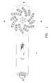
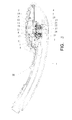
- a mechanism of controlling water outflow of shower is provided in casing 1 of the shower.
- the water outlet of the mechanism aligns with water outflow disc 2.
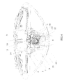
- the mechanism of controlling water outflow comprises an inner sealing shell 3, an outer sealing shell 4 and an intermediate cavity 5 defined between inner sealing shell 3 and outer sealing shell 4.
- a water outflow cavity is formed between outer sealing shell 4 and water outflow disc 2.
- the intermediate cavity 5 communicates with intake channel 6.
- the mechanism of controlling water outflow also comprises separating sealing pad 7 inside the intermediate cavity 5, with one side sticked to the water outflow disc of outer sealing shell 4 and the other side sticked to valve elements.
- the intermediate cavity 5 comprises the inner cavity in the inner side of separating sealing pad and outer cavity 8 in the outer side of separating sealing pad.
- the inner cavity communicates with water outflow cavity through small holes.
- the inner cavity communicates with outer cavity 8 through through-hole 9.
- Intake channel 6 communicates with outer cavity 8.
- the small hole matches with a mobile sealing pad that connects the button kit that controls the sealing pad to separate or contact the small hole.
- the valve elements comprise the first valve element 10 and the second valve element 11.
- the inner cavity comprises the first inner cavity 12 and the second inner cavity 13 isolated each other.
- the water outflow cavity comprises the first water outflow cavity 14 and the second water outflow cavity15 isolated each other.
- the first water outflow cavity14 communicates with the first water outlet 16, while the second water outflow cavity15 communicates with the second water outlet 17.
- the first inner cavity 12 communicates with the first water outflow cavity 14 through the first small hole 18, and communicates with outer cavity 8 through through-hole 9.
- the first small hole 18 matches with the first mobile sealing pad 19 that connects the first button kit that controls the sealing pad 19 to separate or contact small hole18.
- the second inner cavity 13 communicates with the second water outflow cavity15 through the second small hole 20, and communicates with outer cavity 8 through through-hole 9.
- the second small hole 20 matches with the second sealing pad 21 that connects the second button kit that controls the sealing pad 21 to separate or contact the second small hole 20.
- the first button kit comprises the first controlled magnet 22, the first spring 23 and active magnet 24.
- the first controlled magnet 22 is fixedly coupled with the first mobile sealing pad 19, and can be freely invaginated inside the first sliding groove 25 of inner sealing shell 3.
- the first spring 23 sticks tightly the place between the first controlled magnet 22 and the bottom of the first sliding groove 25.
- the active magnet 24 matches with the first controlled magnet 22.
- the second button kit comprises the second controlled magnet 26 and the second spring 27.
- the second controlled magnet 26 is coupled fixedly with the second sealing pad 21, and freely invaginated inside the second sliding groove 28 of inner sealing shell 3.
- the second spring 27 sticks tightly the place between the second controlled magnet 26 and the bottom of the second sliding groove 28.
- the active magnet 24 matches with the second controlled magnet 26.
- a magnetic slideway 29 is provided inside the outer shell and located in the outside of inner sealing shell 3.
- the active magnet 24 is located inside magnetic slideway 29 and is coupled with switch 30 of the shower.
- the switch 30 comprises stop location, the first location to align active magnet 24 with the first controlled magnet 22, and the second location to align active magnet 24 with the second controlled magnet 26.
- the sealing pad uses rubber pad.
Landscapes
- Engineering & Computer Science (AREA)
- General Engineering & Computer Science (AREA)
- Mechanical Engineering (AREA)
- Health & Medical Sciences (AREA)
- Public Health (AREA)
- Life Sciences & Earth Sciences (AREA)
- Hydrology & Water Resources (AREA)
- Water Supply & Treatment (AREA)
- Epidemiology (AREA)
- General Health & Medical Sciences (AREA)
- Nozzles (AREA)
- Bathtubs, Showers, And Their Attachments (AREA)
Applications Claiming Priority (2)
| Application Number | Priority Date | Filing Date | Title |
|---|---|---|---|
| CNB2006100491634A CN100471577C (zh) | 2006-01-17 | 2006-01-17 | 淋浴喷头的出水控制机构 |
| PCT/CN2006/000660 WO2007082418A1 (fr) | 2006-01-17 | 2006-04-13 | Dispositif de réglage de la sortie d'eau d'un pommeau de douche à jet réglable |
Publications (2)
| Publication Number | Publication Date |
|---|---|
| EP1980186A1 true EP1980186A1 (fr) | 2008-10-15 |
| EP1980186A4 EP1980186A4 (fr) | 2012-11-07 |
Family
ID=38287238
Family Applications (1)
| Application Number | Title | Priority Date | Filing Date |
|---|---|---|---|
| EP06741681A Withdrawn EP1980186A4 (fr) | 2006-01-17 | 2006-04-13 | Dispositif de réglage de la sortie d'eau d'un pommeau de douche à jet réglable |
Country Status (6)
| Country | Link |
|---|---|
| US (1) | US7992807B2 (fr) |
| EP (1) | EP1980186A4 (fr) |
| JP (1) | JP4938796B2 (fr) |
| KR (1) | KR101014083B1 (fr) |
| CN (1) | CN100471577C (fr) |
| WO (1) | WO2007082418A1 (fr) |
Cited By (2)
| Publication number | Priority date | Publication date | Assignee | Title |
|---|---|---|---|---|
| CN102886320A (zh) * | 2012-10-18 | 2013-01-23 | 厦门建霖工业有限公司 | 暂停水旋转切换结构 |
| DE102018120982A1 (de) * | 2018-08-28 | 2020-03-05 | Grohe Ag | Brause für eine Sanitärarmatur mit einem Betätigungselement für eine Mehrzahl von Membranventilen |
Families Citing this family (25)
| Publication number | Priority date | Publication date | Assignee | Title |
|---|---|---|---|---|
| CN101428259A (zh) * | 2008-12-01 | 2009-05-13 | 厦门松霖科技有限公司 | 花洒出水推拨切换装置 |
| US8418939B2 (en) * | 2009-12-14 | 2013-04-16 | Xiamen Solex High-Tech Industries Co., Ltd. | Shower having a shower area changed with variation of water pressure |
| WO2011076094A1 (fr) * | 2009-12-21 | 2011-06-30 | 厦门松霖科技有限公司 | Pommeau de douche à corps coulissant |
| WO2012022250A1 (fr) * | 2010-08-17 | 2012-02-23 | 厦门松霖科技有限公司 | Mécanisme de rejet d'eau à commutation tactile |
| DE102010039679A1 (de) * | 2010-08-24 | 2012-03-01 | Hansgrohe Ag | Brause mit einem Gelenk |
| CN102671784B (zh) * | 2012-05-10 | 2014-10-15 | 厦门松霖科技有限公司 | 一种推钮切换阀组及其应用该阀组的花洒 |
| US20150238984A1 (en) * | 2014-02-25 | 2015-08-27 | Ransom Man Pan LEE | Showerhead with spray mode selecting function |
| GB201406475D0 (en) * | 2014-04-10 | 2014-05-28 | Multishower Gb Ltd | A shower head assembly |
| CN104976399A (zh) * | 2015-06-25 | 2015-10-14 | 关学章 | 一种高压花洒龙头 |
| EP3411155B1 (fr) * | 2016-02-01 | 2020-03-25 | Water Pik, Inc. | Lance de pulvérisation portative pour animaux domestiques |
| DE102017106973B3 (de) | 2017-03-31 | 2018-06-21 | Ideal Standard International Nv | Umschaltvorrichtung für eine Sanitärarmatur |
| USD843549S1 (en) | 2017-07-19 | 2019-03-19 | Water Pik, Inc. | Handheld spray nozzle |
| CN107377249B (zh) * | 2017-09-21 | 2023-05-23 | 福建欣宇卫浴科技股份有限公司 | 一种周期性出水机构以及周期性出水花洒 |
| DE102018201109B3 (de) * | 2018-01-24 | 2018-12-27 | Hansgrohe Se | Brausekopf mit Überdruckventil |
| USD872227S1 (en) | 2018-04-20 | 2020-01-07 | Water Pik, Inc. | Handheld spray device |
| JP6810901B2 (ja) * | 2018-09-13 | 2021-01-13 | Toto株式会社 | シャワーヘッド |
| CN109550606B (zh) * | 2018-12-12 | 2024-04-09 | 厦门松霖科技股份有限公司 | 一种出水切换机构和出水切换的操作机构 |
| CN109718955B (zh) * | 2019-03-08 | 2024-02-27 | 九牧厨卫股份有限公司 | 一种超薄自动除垢花洒 |
| CN110882866B (zh) * | 2019-11-05 | 2024-06-04 | 厦门建霖健康家居股份有限公司 | 一种出水装置 |
| CN119387059A (zh) * | 2021-04-02 | 2025-02-07 | 厦门松霖科技股份有限公司 | 出水装置 |
| CN113133440B (zh) * | 2021-04-25 | 2022-06-17 | 山西农业大学 | 一种具有多方位喷洒功能的喷洒车及其控制方法 |
| CN114903631B (zh) * | 2022-05-31 | 2023-09-12 | 广东固特科技有限公司 | 一种超声波洁牙器换能器 |
| CN116202464B (zh) * | 2023-03-06 | 2025-11-04 | 广汽本田汽车有限公司 | 一种脱漆辅助装置和一种电泳膜厚度测量方法 |
| CN116273524B (zh) * | 2023-04-06 | 2025-11-11 | 华南建材(深圳)有限公司 | 一种侧喷淋的船舱卫浴出水装置 |
| CA232258S (en) * | 2024-06-04 | 2025-05-29 | Sinyu Tech Fujian Co Ltd | Spray head for shower |
Family Cites Families (17)
| Publication number | Priority date | Publication date | Assignee | Title |
|---|---|---|---|---|
| EP0499151B1 (fr) * | 1991-02-12 | 1995-06-21 | Toto Ltd. | Dispensateur d'eau à tête rotative entraînée par un petit moteur |
| US5427318A (en) * | 1993-01-13 | 1995-06-27 | Lee; Duck S. | One-touch on-off showerhead valve |
| DE4341650A1 (de) * | 1993-12-07 | 1995-06-08 | Grohe Armaturen Friedrich | Selbstschlußventil |
| US5433384A (en) | 1994-06-24 | 1995-07-18 | Jing Mei Industrial Limited | Push button controlled multifunction shower head |
| US5476225A (en) | 1994-06-24 | 1995-12-19 | Jing Mei Industrial Limited | Multi spray pattern shower head |
| IT1293134B1 (it) * | 1997-05-05 | 1999-02-12 | Gevipi Ag | Doccetta alimentata da tubazione flessibile, con commutazione della modalita' di erogazione. |
| US6282730B1 (en) * | 1998-04-15 | 2001-09-04 | E-Ticket Enterprises, Llc | Magnetic stopper |
| JP2000037641A (ja) * | 1998-07-22 | 2000-02-08 | Tokyo Gas Co Ltd | シャワーヘッド |
| US6230989B1 (en) | 1998-08-26 | 2001-05-15 | Water Pik, Inc. | Multi-functional shower head |
| DE10103649B4 (de) * | 2001-01-27 | 2007-12-06 | Hansgrohe Ag | Brausekopf |
| US20020176522A1 (en) * | 2001-05-25 | 2002-11-28 | Koninklijke Phillips Electronics N.V. | Quadrature envelope-sampling of intermediate frequency signal in receiver |
| WO2004067859A1 (fr) * | 2003-01-29 | 2004-08-12 | Youngsung Industrial Co., Ltd. | Appareil a tete multifonctions utilise avec une conduite d'amenee disposant d'une fonction de purification |
| KR200317649Y1 (ko) | 2003-04-02 | 2003-06-25 | 김근수 | 샤워장치 |
| US20040217209A1 (en) * | 2003-04-11 | 2004-11-04 | Interbath, Inc. | Thin profile multi-function showerhead |
| DE202005008082U1 (de) | 2005-05-19 | 2005-08-04 | Chang, Tsung-Chieh, Da Li | Duschkopf-Aufbau mit einer Modus-Steuervorrichtung |
| US7303151B2 (en) * | 2005-06-07 | 2007-12-04 | James Wu | Shower head assembly |
| US7100845B1 (en) * | 2005-10-24 | 2006-09-05 | Elvis Hsieh | Switch-equipped sprinkler |
-
2006
- 2006-01-17 CN CNB2006100491634A patent/CN100471577C/zh not_active Expired - Fee Related
- 2006-04-13 WO PCT/CN2006/000660 patent/WO2007082418A1/fr not_active Ceased
- 2006-04-13 US US12/087,900 patent/US7992807B2/en not_active Expired - Fee Related
- 2006-04-13 JP JP2008550605A patent/JP4938796B2/ja not_active Expired - Fee Related
- 2006-04-13 KR KR1020087018350A patent/KR101014083B1/ko not_active Expired - Fee Related
- 2006-04-13 EP EP06741681A patent/EP1980186A4/fr not_active Withdrawn
Cited By (4)
| Publication number | Priority date | Publication date | Assignee | Title |
|---|---|---|---|---|
| CN102886320A (zh) * | 2012-10-18 | 2013-01-23 | 厦门建霖工业有限公司 | 暂停水旋转切换结构 |
| CN102886320B (zh) * | 2012-10-18 | 2015-05-06 | 厦门建霖工业有限公司 | 暂停水旋转切换结构 |
| DE102018120982A1 (de) * | 2018-08-28 | 2020-03-05 | Grohe Ag | Brause für eine Sanitärarmatur mit einem Betätigungselement für eine Mehrzahl von Membranventilen |
| EP3844351A1 (fr) * | 2018-08-28 | 2021-07-07 | Grohe AG | Pomme de douche destinée à une robinetterie sanitaire dotée d'un élément de déplacement destiné à une pluralité de soupapes à membrane |
Also Published As
| Publication number | Publication date |
|---|---|
| US7992807B2 (en) | 2011-08-09 |
| WO2007082418A1 (fr) | 2007-07-26 |
| JP2009523599A (ja) | 2009-06-25 |
| EP1980186A4 (fr) | 2012-11-07 |
| JP4938796B2 (ja) | 2012-05-23 |
| KR20080089449A (ko) | 2008-10-06 |
| CN101003031A (zh) | 2007-07-25 |
| KR101014083B1 (ko) | 2011-02-14 |
| CN100471577C (zh) | 2009-03-25 |
| US20100301141A1 (en) | 2010-12-02 |
Similar Documents
| Publication | Publication Date | Title |
|---|---|---|
| EP1980186A1 (fr) | Dispositif de réglage de la sortie d'eau d'un pommeau de douche à jet réglable | |
| EP3135832B1 (fr) | Tête de pulvérisation tactile | |
| CN101793331B (zh) | 管道截止或切换开关阀 | |
| CN201223832Y (zh) | 拉出式龙头功能水切换装置 | |
| DE60138238D1 (de) | Herausziehbarer Brausekopf für die Küche | |
| CN210097974U (zh) | 一种组合花洒 | |
| EP2246119A3 (fr) | Ensemble de commande de pulvérisation pour robinet | |
| CN109174479B (zh) | 一种花洒节水切换结构及花洒 | |
| US11850607B2 (en) | Shower device | |
| CN110594443A (zh) | 一种带漱口水功能的龙头 | |
| CN109764144B (zh) | 一种双模式节流球阀 | |
| CN112642600B (zh) | 一种带止水和流量控制的出水装置 | |
| CN101767070A (zh) | 滑动切换花洒 | |
| CN204933764U (zh) | 一种推钮切换组件及应用该组件的花洒 | |
| CN206168592U (zh) | 一种按钮切换机构及采用该切换机构的花洒 | |
| CN212131385U (zh) | 一种淋浴装置 | |
| CN221003985U (zh) | 一种抽拉控制出水的龙头 | |
| CN218222961U (zh) | 一种出水装置的水路切换结构及花洒 | |
| CN209115732U (zh) | 一种新型淋浴龙头结构 | |
| CN204953161U (zh) | 智能化换挡顶喷花洒 | |
| CN108273679A (zh) | 薄型花洒及水路切换装置 | |
| CN201368226Y (zh) | 拉出式龙头出水切换结构 | |
| CN210128097U (zh) | 一种插座装置 | |
| CN200991665Y (zh) | 手持花洒单手调节结构 | |
| CN211039782U (zh) | 一种按钮切换结构 |
Legal Events
| Date | Code | Title | Description |
|---|---|---|---|
| PUAI | Public reference made under article 153(3) epc to a published international application that has entered the european phase |
Free format text: ORIGINAL CODE: 0009012 |
|
| 17P | Request for examination filed |
Effective date: 20080813 |
|
| AK | Designated contracting states |
Kind code of ref document: A1 Designated state(s): AT BE BG CH CY CZ DE DK EE ES FI FR GB GR HU IE IS IT LI LT LU LV MC NL PL PT RO SE SI SK TR |
|
| DAX | Request for extension of the european patent (deleted) | ||
| A4 | Supplementary search report drawn up and despatched |
Effective date: 20121005 |
|
| RIC1 | Information provided on ipc code assigned before grant |
Ipc: E03C 1/04 20060101ALI20120928BHEP Ipc: B05B 1/18 20060101ALI20120928BHEP Ipc: B05B 1/00 20060101ALI20120928BHEP Ipc: B05B 12/00 20060101ALI20120928BHEP Ipc: A47K 3/28 20060101AFI20120928BHEP Ipc: F16K 37/00 20060101ALI20120928BHEP Ipc: B05B 1/16 20060101ALI20120928BHEP |
|
| RIC1 | Information provided on ipc code assigned before grant |
Ipc: B05B 1/34 20060101AFI20131031BHEP Ipc: F16K 31/385 20060101ALI20131031BHEP Ipc: E03C 1/04 20060101ALI20131031BHEP Ipc: B05B 1/18 20060101ALI20131031BHEP Ipc: F16K 31/08 20060101ALI20131031BHEP Ipc: F16K 11/16 20060101ALI20131031BHEP Ipc: B05B 1/16 20060101ALI20131031BHEP |
|
| GRAP | Despatch of communication of intention to grant a patent |
Free format text: ORIGINAL CODE: EPIDOSNIGR1 |
|
| INTG | Intention to grant announced |
Effective date: 20131212 |
|
| GRAS | Grant fee paid |
Free format text: ORIGINAL CODE: EPIDOSNIGR3 |
|
| STAA | Information on the status of an ep patent application or granted ep patent |
Free format text: STATUS: THE APPLICATION IS DEEMED TO BE WITHDRAWN |
|
| 18D | Application deemed to be withdrawn |
Effective date: 20140423 |