EP1980706A2 - Tensionneur de corde en boucle pour couverture architecturale - Google Patents
Tensionneur de corde en boucle pour couverture architecturale Download PDFInfo
- Publication number
- EP1980706A2 EP1980706A2 EP08251345A EP08251345A EP1980706A2 EP 1980706 A2 EP1980706 A2 EP 1980706A2 EP 08251345 A EP08251345 A EP 08251345A EP 08251345 A EP08251345 A EP 08251345A EP 1980706 A2 EP1980706 A2 EP 1980706A2
- Authority
- EP
- European Patent Office
- Prior art keywords
- cord
- looped
- housing
- tensioner
- slide member
- Prior art date
- Legal status (The legal status is an assumption and is not a legal conclusion. Google has not performed a legal analysis and makes no representation as to the accuracy of the status listed.)
- Withdrawn
Links
- 238000009434 installation Methods 0.000 claims abstract description 7
- 230000000717 retained effect Effects 0.000 claims 1
- 238000011282 treatment Methods 0.000 description 10
- 230000008901 benefit Effects 0.000 description 4
- 239000000463 material Substances 0.000 description 4
- 230000004087 circulation Effects 0.000 description 3
- 208000027418 Wounds and injury Diseases 0.000 description 2
- 230000001413 cellular effect Effects 0.000 description 2
- 230000006378 damage Effects 0.000 description 2
- 208000014674 injury Diseases 0.000 description 2
- 238000000034 method Methods 0.000 description 2
- 239000004677 Nylon Substances 0.000 description 1
- 229910000831 Steel Inorganic materials 0.000 description 1
- XAGFODPZIPBFFR-UHFFFAOYSA-N aluminium Chemical compound [Al] XAGFODPZIPBFFR-UHFFFAOYSA-N 0.000 description 1
- 229910052782 aluminium Inorganic materials 0.000 description 1
- 230000036541 health Effects 0.000 description 1
- 231100000206 health hazard Toxicity 0.000 description 1
- 229920001778 nylon Polymers 0.000 description 1
- 230000008569 process Effects 0.000 description 1
- 230000007480 spreading Effects 0.000 description 1
- 239000010959 steel Substances 0.000 description 1
Images


Classifications
-
- E—FIXED CONSTRUCTIONS
- E06—DOORS, WINDOWS, SHUTTERS, OR ROLLER BLINDS IN GENERAL; LADDERS
- E06B—FIXED OR MOVABLE CLOSURES FOR OPENINGS IN BUILDINGS, VEHICLES, FENCES OR LIKE ENCLOSURES IN GENERAL, e.g. DOORS, WINDOWS, BLINDS, GATES
- E06B9/00—Screening or protective devices for wall or similar openings, with or without operating or securing mechanisms; Closures of similar construction
- E06B9/24—Screens or other constructions affording protection against light, especially against sunshine; Similar screens for privacy or appearance; Slat blinds
- E06B9/26—Lamellar or like blinds, e.g. venetian blinds
- E06B9/28—Lamellar or like blinds, e.g. venetian blinds with horizontal lamellae, e.g. non-liftable
- E06B9/30—Lamellar or like blinds, e.g. venetian blinds with horizontal lamellae, e.g. non-liftable liftable
- E06B9/32—Operating, guiding, or securing devices therefor
- E06B9/326—Details of cords, e.g. buckles, drawing knobs
-
- E—FIXED CONSTRUCTIONS
- E06—DOORS, WINDOWS, SHUTTERS, OR ROLLER BLINDS IN GENERAL; LADDERS
- E06B—FIXED OR MOVABLE CLOSURES FOR OPENINGS IN BUILDINGS, VEHICLES, FENCES OR LIKE ENCLOSURES IN GENERAL, e.g. DOORS, WINDOWS, BLINDS, GATES
- E06B9/00—Screening or protective devices for wall or similar openings, with or without operating or securing mechanisms; Closures of similar construction
- E06B9/24—Screens or other constructions affording protection against light, especially against sunshine; Similar screens for privacy or appearance; Slat blinds
- E06B9/26—Lamellar or like blinds, e.g. venetian blinds
- E06B9/28—Lamellar or like blinds, e.g. venetian blinds with horizontal lamellae, e.g. non-liftable
- E06B9/30—Lamellar or like blinds, e.g. venetian blinds with horizontal lamellae, e.g. non-liftable liftable
- E06B9/32—Operating, guiding, or securing devices therefor
- E06B9/326—Details of cords, e.g. buckles, drawing knobs
- E06B2009/3265—Emergency release to prevent strangulation or excessive load
Definitions
- the present invention relates generally to looped-cord tensioners for architectural coverings and treatments, such as blinds, curtains, and the like. More particularly, the present invention relates to a looped-cord tensioner that prevents operation of the architectural covering unless the tensioner is first mounted to a wall or other non-moveable structure.
- a looped-cord or continuous looped-cord Such cords are distinct from the basic pull cord style shades in that the looped-cord does not connect directly to the shade material, but rather engages a clutch on a rotating shaft in a headrail of the shade. Movement of the looped-cord in a first direction operates that clutch to accumulate shade material when opening, and movement of the looped-cord in a second direction lets out shade material.
- the looped-cord may be made at different lengths than the shade and may be configured to make multiple circulations during opening and closing of the shade.
- a looped-cord system versus a standard pull cord system are that the exposed looped-cord remains at a constant length whether the shade is open or closed (avoiding the problem of stowing the long exposed pull cord when the shade is opened). Moreover, a looped-cord system also provides a mechanical advantage to raise relatively large, heavy shades with reasonable cord forces.
- looped-cords also have a significant disadvantage. Generally, looped-cords hang freely along a side of the shade they are used to operate. Many looped-cords are long enough that they reach the floor and are easily grasped by babies and young children as a potential play toy. Rather than a play toy, however, a dangling looped-cord has proved to be a health hazard to babies and young children. In recent years, cases of death or injury have been documented in which a person, typically a baby or a small child, has become entangled in the looped-cord and has choked or become asphyxiated when the looped-cord became wrapped around their neck and constricted their airways.
- a tensioner typically includes a two-piece housing with a through passage for a looped-cord and a provision for attaching the tensioner to a wall or other fixed structure.
- the tensioner is designed to be mounted to a wall or other non-movable structure at some distance away from the clutch.
- the tensioner allows the looped-cord to be pulled taut during the mounting process, at rest, and during operation, so that it may be difficult to spread the two sides of the looped-cord apart enough for it to pass over a child's head, thereby preventing injury and possibly death.
- One design includes a tensioning spring between a cord contacting member and a tensioner mounting body. This improved design allows the tensioner to be mounted with the looped-cords fully taut and the tensioning spring partially loaded. The pre-loaded spring holds the looped-cord taut while not in operation, thus preventing a baby or young child from spreading the looped-cord wide enough to pass their head through. During operation of the looped-cord, an adult operating the looped-cord will be able to overcome the remainder of the spring loading and easily pull the looped-cord to open or close the shade.
- a looped-cord tensioner for an architectural covering including a housing adapted for attachment to a looped-cord, an abutment member positioned within the housing, a slide member positioned within the housing, and at least one biasing element having a first end and a second end.
- One of the slide member and the abutment member is adapted to engage the second end of the biasing element and the first end of said biasing element is adapted to engage the housing such that one of the slide member and the abutment member is moveably positioned in the housing so as to bias one of the slide member and the abutment member toward engagement with the looped-cord such that the looped-cord is normally non-movably sandwiched between the slide member and the abutment member prior to installation of the looped-cord tensioner.
- One of the slide member and the housing is adapted to be fixedly installed to a non-movable structure adjacent the architectural covering such that one of the slide member and the abutment member is disengaged from the looped-cord and the looped-cord is free to moveably pass through the housing following proper installation.
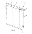
- FIG. 1 is a perspective view of a looped-cord window treatment that includes an improved looped-cord tensioner according to an embodiment of the present invention
- FIGS. 2A and 2B are side views of male and female portions, respectively, of a looped-cord tensioner according to an embodiment of the present invention
- FIGS. 3A and 3B are perspective views of a looped-cord tensioner according to another embodiment of the present invention.
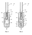
- FIG. 4 is side view of a looped-cord tensioner according to another embodiment of the present invention.
- FIG. 5 is side view of a looped-cord tensioner according to another embodiment of the present invention.
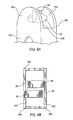
- FIGS. 6A and 6B are a perspective view and top view, respectively, of a looped-cord tensioner according to another embodiment of the present invention.
- FIG. 1 there is shown a partial view of a looped-cord window treatment 8 that includes a shade 10, a headrail 12, a bottom rail 14, and at least one lift cord 16.
- Headrail 12 is mounted above a window or door unit and shade 10 is attached to headrail 12 and allowed to hang vertically to cover the window or door unit.
- Bottom rail 14 is attached to the bottom of shade 10 to add weight to shade 10, which ensures that shade 10 may be lowered quickly, covers the window or door unit properly, and is not easily blown around by the wind if the window or door unit is open.
- Bottom rail 14 also serves as an attachment point for lift cord 16 so that shade 10 may be raised and lowered.
- Lift cord 16 may also attach at one or more points along shade 10, however, the major pulling force is on the bottom rail 16 during raising and lowering of shade 10 so that shade 10 is not damaged by the pulling forces of lift cord 16.
- Headrail 12 includes a rotating shaft 18 having a clutch 20.
- Clutch 20 includes a looped-cord 22 that is used in operating clutch 20 to raise and lower shade 10.
- Lift cord 16 is attached to rotating shaft 18 and is wound about rotating shaft 18 during the raising of shade 10 and unwound during the lowering of shade 10.
- Looped-cord 22 does not connect directly to shade 10, but rather drives clutch 20, which in turn rotates shaft 18 and either winds lift cord 16 on shaft 18 to raise shade 10 or unwinds lift cord 16 from shaft 18 to lower shade 10.
- Looped-cord 22 may be made at different lengths than shade 10 and may be configured to make multiple circulations during operation of clutch 20.
- a looped-cord tensioner 24 is mounted to a wall or other non-movable structure adjacent to shade 10.
- the window treatment design shown in FIG. 1 includes a constant length of exposed looped-cord 22 (avoiding the problem of stowing a long exposed cord found in pull-cord style window treatment designs while the treatment is open). Moreover, loop-cord 22 and clutch 20 cooperatively provide a mechanical advantage to raise relatively large, heavy shades with reasonable looped-cord 22 forces.
- tensioner 24 includes a male member 26, a female member 28, a sliding lock 30, and a biasing element 32.
- Male member 26 includes a first surface 34 having a wall 36 extending outward from and generally perpendicular to first surface 34. Wall 36 surrounds three sides of first surface 34 and includes a shoulder 38 for accepting female member 28.
- a top edge 40 of wall 36 includes locking tabs 42 (also see 42' in FIGS. 3A and 3B ) for securing male member 26 to female member 28.
- an interior portion 44 of first surface 34 includes an abutment member 46.
- abutment member 46 is an outer cylinder having slots 72 for engaging locking tabs 48 of an inner cylinder 50 on female member 28 (also see 72' and 48' in FIGS. 3A and 3B ).
- Interior portion 44 further includes at least one support wall 52 for supporting female member 28 during operation of tensioner 24.
- Interior portion 44 also includes a slot 54 for accepting a portion of lock 30 to allow lock 30 to slide within male member 26.
- lock 30 that enters slot 54 is a boss 31 that extends from either relatively flat surface of lock 30 and includes a hole 56 to accept a fastener, such as a screw, so that tensioner 24 may be mounted to a wall or other non-moveable structure.
- Lock 30 also includes a first engagement surface 58 for engaging a first end of biasing element 32, which is shown as being a spring.
- Interior portion 44 may also include at least one post 60 having a second engagement surface 61 for engaging a second end of biasing element 32. Alternatively, post 60 may be omitted and the second end of biasing element 32 may engage an interior surface of wall 36.
- female member 28 includes a second surface 62 having a wall 64 extending outward from and generally perpendicular to second surface 62.
- Wall 64 surrounds three sides of second surface 62 and includes an edge 66 that abuts shoulder 28 of male member 24 when tensioner 24 is assembled.
- Wall 64 also includes depressions 68 for accepting locking tabs 42 to secure female member 28 to male member 26.
- An interior portion 70 of second surface 62 includes inner cylinder 50 sized to be inserted into outer cylinder 46 as male member 26 is assembled to female member 28.
- Interior portion 70 also includes a slot 74 for accepting boss 31 of lock 30 to allow lock 30 to slide within female member 26.
- lock 30 may be generally rectangular in shape with hole 56 passing though boss 31 to accept the fastener.
- Lock 30 may also include a face 76 at an edge 78 that engages and locks looped-cord 22 against movement when lock 30 is not in tension (i.e. tensioner 24 is not secured to a wall or other non-moveable structure by lock 30).
- Face 76 of lock 30 may be of any general shape, provided face 76 engages and locks looped-cord 22 and prevents operation of looped-cord 22 until tensioner 24 is properly mounted.
- Face 76 may be serrated, saw-toothed, cleated or have some other means of increasing the friction between the face/looped-cord 76/22 interface to prevent movement of looped-cord 22 within tensioner 24 until tensioner 24 is properly mounted.
- boss 31 surrounds hole 56 that passes though lock 30.
- Boss 31 is sized to fit into slots 54 and 74, such that tensioner 24 permits lock 30 to be moved within slots 54 and 74 and allows the disengagement of face 76 from looped-cord 22 when lock 30 is moved out of engagement with looped-cord 22.
- Components of tensioner 24 may be manufactured from any metallic or polymeric material, such as aluminum, steel, nylon, and the like.
- tensioner 24 is assembled in the following manner. First, looped-cord 22 is placed onto outer cylinder 46 of male member 26. Next, lock 30 is set in slot 54 of male member 26 such that boss 31 extends through slot 54 and biasing element 32 is positioned between lock 30 and post 60 at first and second engagement points 58 and 61, respectively. Face 76 of lock 30 is now in engagement with looped-cord 22 to prevent its movement about cylinder 46. Female member 28 is then press-fit onto male member 26 so that locking tabs 42 engage depressions 68 and locking tabs 48 of inner cylinder 50 engage slots 72 of outer cylinder 46 forming a resilient interference fit. Boss 31 now extends through slot 74 of female member 28 as well. As stated above, lock 30 is positioned such that face 76 engages and locks looped-cord 22 and prevents movement of looped-cord 22 within tensioner 24.
- shade 10 should first be installed in a location determined by the user, usually over a window unit or other architectural opening. After installation of shade 10, tensioner 24 is located and secured to a wall or other non-movable structure adjacent shade 10 in the following manner. Tensioner 24 is located on the wall such that all the slack has been removed from looped-cord 22. Once tensioner 24 has been positioned on the wall such that looped-cord 22 is taut, lock 30 may be slid downward through slots 54 and 74, compressing biasing element 32, such that face 76 will disengage and unlock looped-cord 22.
- a fastener should be driven through hole 56 of lock 30 and into a wall to position lock 30 in a manner that does not inhibit the movement of looped-cord 22 around outer cylinder 46.
- Positioning of lock 30 in this manner allows looped-cord 22 to enter and exit tensioner 24 freely in order to make multiple circulations so that shade 10 may be raised and lowered. Only by properly installing tensioner 24, which compresses its biasing element 32, thereby unlocking looped-cord 22, may looped-cord 22 travel freely through tensioner 24 to permit operation of shade 10. Following installation, biasing element 32 continues to exert a downward force on post 60 and members 26 and 28, thereby maintaining the desired tautness in looped-cord 22.
- tensioner 24 in another embodiment of tensioner 24 is shown (denoted as 24'), which includes a sliding lock 30' that is generally circular in shape and has two arms 81 that serve as attachment points for biasing elements 32'.
- tensioner 24' includes a pair of biasing elements 32', such as tensioner springs. Each biasing element 32' is attached to a point on arm 81 and to posts 60' of male member 26'. Face 76' of lock 30' may be serrated or cleated as in the prior embodiment. Assembly and operation of tensioner 24' is substantially similar to that described above with respect to tensioner 24 and, therefore, will not be described in further detail here.
- a tensioner 24" is provided that includes the attachments in reverse. Looped-cord 22 may be attached to tensioner 24" at abutment member 46" that is allowed to slide within tensioner 24".
- the attaching point for tensioner 24" to the wall or other non-movable structure is a hole 90 through the member 26" and female member (not shown) of tensioner 24". Abutment member 46" is allowed to slide freely in slot 54" and is attached to male member 26" by biasing element 33.
- sliding lock 30" is configured to be non-movable within tensioner 24" and may include a face 76 to engage and lock looped-cord 22 as previously described.
- tensioner 24" is as described above as well. These embodiments are illustrative of a number of different configurations of tensioner 24, yet the underlying operation of the invention is the same, preventing the operation of looped-cord 22 in shade 10 unless tensioner 24 is properly mounted to an adjacent wall or other non-movable structure.
- a tensioner 24'" is provided that includes abutment member 46" that is allowed to slide freely in slot 54'" as well as the slot in the corresponding female member (not shown). Looped-cord 22 may be looped around abutment member 46" as discussed in previous embodiments.
- Sliding lock 30 is employed as discussed above with the descriptions relating to FIGS. 2A and 2B . Face 76 of sliding lock 30 engages and locks looped-cord 22, also discussed above in relation to the embodiments illustrated in FIGS. 2A and 2B .
- both abutment member 46" and sliding lock 30 are moveable within tensioner 24"'. The assembly and operation of tensioner 24"' is as described in the previous embodiments above.
- each of these embodiments are illustrative of a number of different configurations of tensioner 24, yet the underlying operation of the invention is the same-preventing operation of looped-cord 22 in shade 10 unless tensioner 24 is properly mounted to an adjacent wall or other non-movable structure.
- a tensioner 240 is provided that allows looped-cord 22 to be inserted into the tensioner after complete assembly of tensioner 240, and thereafter prevent removal of looped-cord 22 from tensioner 240.
- abutment member is a pair of tabs 82 and 84. Inner and outer cylinders 46, 50 of tensioner 24 have been replaced with tabs 82 and 84.
- a first tab 82 extends generally perpendicular from interior portion 440 of male member 260 near an opening where looped-cord 22 enters tensioner 240.
- a second tab 84 extends generally perpendicular from interior portion 700 of female member 280 near the opening where looped-cord 22 enters tensioner 240.
- Each tab 82, 84 extends out a length from interior portion 440, 700 sufficient to form gaps 86 and 88 between tabs 82, 84 and interior portions 440, 700 when tensioner 240 is fully assembled. In this manner, looped-cord 22 may be forced through gaps 86 and 88 (by flexing member halves 26 and 28) so that tensioner 240 can be attached to looped-cord 22.
- Both tabs 82 and 84 have curved surfaces for interfacing with looped-cord 22 so that looped-cord 22 is not damaged as looped-cord 22 rubs against tabs 82, 84 during operation of shade 10. Also, cord 22 may not be easily removed from tensioner 240 without forcibly prying apart members 260 and 280 or destroying tabs 82 and 84. Tensioner 240 is then mounted to the wall in the same manner as described above to disengage face 76 from looped-cord 22 to allow for raising and lowering of shade 10.
- the present invention may be used with any number of different window treatments including cellular shades, Venetian blinds, other pleated shades, and the like, which employ looped cords for opening and closing the window treatment.
- window treatments including cellular shades, Venetian blinds, other pleated shades, and the like, which employ looped cords for opening and closing the window treatment.
- the preferred embodiment is described and shown for use with window treatments, it is important to note, however, that the present invention is not so limited and may be used with any architectural covering that requires a looped-cord for operation.
Landscapes
- Engineering & Computer Science (AREA)
- Structural Engineering (AREA)
- Architecture (AREA)
- Civil Engineering (AREA)
- Blinds (AREA)
- Load-Engaging Elements For Cranes (AREA)
- Power-Operated Mechanisms For Wings (AREA)
Applications Claiming Priority (1)
| Application Number | Priority Date | Filing Date | Title |
|---|---|---|---|
| US11/733,582 US20080251622A1 (en) | 2007-04-10 | 2007-04-10 | Looped-cord tensioner for an architectural covering |
Publications (1)
| Publication Number | Publication Date |
|---|---|
| EP1980706A2 true EP1980706A2 (fr) | 2008-10-15 |
Family
ID=39608400
Family Applications (1)
| Application Number | Title | Priority Date | Filing Date |
|---|---|---|---|
| EP08251345A Withdrawn EP1980706A2 (fr) | 2007-04-10 | 2008-04-07 | Tensionneur de corde en boucle pour couverture architecturale |
Country Status (6)
| Country | Link |
|---|---|
| US (1) | US20080251622A1 (fr) |
| EP (1) | EP1980706A2 (fr) |
| CN (1) | CN101372884A (fr) |
| AU (1) | AU2008201518A1 (fr) |
| BR (1) | BRPI0801001A2 (fr) |
| CA (1) | CA2627643A1 (fr) |
Cited By (5)
| Publication number | Priority date | Publication date | Assignee | Title |
|---|---|---|---|---|
| US8197862B2 (en) | 2007-08-21 | 2012-06-12 | Dsm Ip Assets B.V. | Method of making distilled olive juice extracts |
| KR101159248B1 (ko) | 2011-07-28 | 2012-06-25 | 김범식 | 블라인드용 안전 보호구 |
| EP2565362A1 (fr) * | 2011-08-30 | 2013-03-06 | WholeSpace Industries, Ltd. | Dispositif de tensionnement de corde en boucle pour garnitures de fenêtre |
| EP2573311B1 (fr) * | 2011-09-22 | 2018-11-07 | Whole Space Industries Ltd | Système de corde en boucle pour les couvertures de fenêtre |
| US20250116157A1 (en) * | 2023-10-05 | 2025-04-10 | Hunter Douglas Inc. | Tensioner for an architectural-structure covering |
Families Citing this family (14)
| Publication number | Priority date | Publication date | Assignee | Title |
|---|---|---|---|---|
| US20110214258A1 (en) * | 2010-03-04 | 2011-09-08 | Kristi Lee Seymour | Safety device for corded window treatments |
| US8376022B2 (en) | 2011-02-18 | 2013-02-19 | Whole Space Industries Ltd | Loop cord tension device for window coverings |
| CN102727063B (zh) * | 2011-04-07 | 2014-02-26 | 嘉仪企业股份有限公司 | 窗帘珠链安全装置 |
| ITMI20121292A1 (it) * | 2012-07-25 | 2014-01-26 | Pellini Spa | Dispositivo per comandare l'azionamento di un gruppo di movimentazione di una tenda |
| US20140262081A1 (en) * | 2013-03-14 | 2014-09-18 | Draper, Inc. | Window shade roller support |
| JP6266640B2 (ja) * | 2013-10-18 | 2018-01-24 | 立川ブラインド工業株式会社 | コードイコライザー、遮蔽装置 |
| US20150121762A1 (en) * | 2013-11-05 | 2015-05-07 | Tser Wen Chou | Pull cord fixing support for inner and outer windows |
| KR101644171B1 (ko) | 2014-12-16 | 2016-07-29 | 주식회사 윈플러스 | 블라인드 조정줄용 안전장치 |
| KR101938676B1 (ko) * | 2017-03-15 | 2019-01-15 | 지상훈 | 당김줄 수축장치 |
| ES1190860Y (es) * | 2017-08-04 | 2017-11-27 | Bandalux Ind S A | Dispositivo de seguridad para una cadena de una cortina |
| US11098528B2 (en) | 2018-06-19 | 2021-08-24 | Hunter Douglas Inc. | Tensioner for an architectural-structure covering |
| CN110500022A (zh) * | 2019-07-08 | 2019-11-26 | 南京沐鼎节能建材有限公司 | 一种内置百叶中空玻璃用的紧凑张紧装置 |
| US20250250850A1 (en) * | 2024-02-05 | 2025-08-07 | Coulisse B.V. | Tension device for an endless operating loop of a screen |
| TWM665778U (zh) * | 2024-03-26 | 2025-01-21 | 應誠窗簾股份有限公司 | 珠鍊/拉繩固定器 |
Family Cites Families (8)
| Publication number | Priority date | Publication date | Assignee | Title |
|---|---|---|---|---|
| US2465621A (en) * | 1946-05-27 | 1949-03-29 | Harrison S Wheeler | Tarpaulin anchor |
| US4366852A (en) * | 1980-12-05 | 1983-01-04 | Joanna Western Mills Company | Cord weight assembly |
| US5709258A (en) * | 1996-05-02 | 1998-01-20 | Advanced Design Group, Llc | Safety arrangement for window blinds |
| US5819832A (en) * | 1997-04-18 | 1998-10-13 | Huang; Tai-Long | Operating device for a venetian blind to control raising and lowering of the slats and to adjust tilting angle of the slats |
| US5845696A (en) * | 1998-05-01 | 1998-12-08 | Rainbow Industrial, Inc. | Chain and cord safety device for adjustable blinds |
| US6085824A (en) * | 1998-05-13 | 2000-07-11 | All-Teck Blinds, P.T.B. Inc. | Control cord end security device |
| USD428292S (en) * | 1999-02-16 | 2000-07-18 | Anderson Richard N | Cord tensioner for pull cords in architectural coverings |
| US7114544B2 (en) * | 2004-09-07 | 2006-10-03 | Hunter Douglas Inc. | Cord tensioner for covering for architectural openings |
-
2007
- 2007-04-10 US US11/733,582 patent/US20080251622A1/en not_active Abandoned
-
2008
- 2008-03-25 CA CA002627643A patent/CA2627643A1/fr not_active Abandoned
- 2008-04-03 AU AU2008201518A patent/AU2008201518A1/en not_active Abandoned
- 2008-04-07 EP EP08251345A patent/EP1980706A2/fr not_active Withdrawn
- 2008-04-08 BR BRPI0801001-3A patent/BRPI0801001A2/pt not_active IP Right Cessation
- 2008-04-10 CN CNA2008100919260A patent/CN101372884A/zh active Pending
Cited By (6)
| Publication number | Priority date | Publication date | Assignee | Title |
|---|---|---|---|---|
| US8197862B2 (en) | 2007-08-21 | 2012-06-12 | Dsm Ip Assets B.V. | Method of making distilled olive juice extracts |
| KR101159248B1 (ko) | 2011-07-28 | 2012-06-25 | 김범식 | 블라인드용 안전 보호구 |
| WO2013015643A3 (fr) * | 2011-07-28 | 2013-04-11 | Kim Bumsic | Protection de sécurité pour store |
| EP2565362A1 (fr) * | 2011-08-30 | 2013-03-06 | WholeSpace Industries, Ltd. | Dispositif de tensionnement de corde en boucle pour garnitures de fenêtre |
| EP2573311B1 (fr) * | 2011-09-22 | 2018-11-07 | Whole Space Industries Ltd | Système de corde en boucle pour les couvertures de fenêtre |
| US20250116157A1 (en) * | 2023-10-05 | 2025-04-10 | Hunter Douglas Inc. | Tensioner for an architectural-structure covering |
Also Published As
| Publication number | Publication date |
|---|---|
| BRPI0801001A2 (pt) | 2008-11-25 |
| CN101372884A (zh) | 2009-02-25 |
| CA2627643A1 (fr) | 2008-10-10 |
| AU2008201518A1 (en) | 2008-10-30 |
| US20080251622A1 (en) | 2008-10-16 |
Similar Documents
| Publication | Publication Date | Title |
|---|---|---|
| US20080251622A1 (en) | Looped-cord tensioner for an architectural covering | |
| US9506290B2 (en) | Tension device for looped-cord system | |
| US8376022B2 (en) | Loop cord tension device for window coverings | |
| CN100470004C (zh) | 无绳式百叶窗用的制动装置 | |
| US8763671B2 (en) | Cordless covering for architectural opening | |
| US8496040B2 (en) | Method and apparatus for fixing the length of a pull cord | |
| US5279473A (en) | Cord retraction device | |
| US8950463B2 (en) | Cordless coverings for architectural opening having cord enclosures with a swivel feature and methods of assembling such cord enclosures | |
| US8967226B2 (en) | Architectural cover operating assembly | |
| US5533559A (en) | Window shade assembly with hold down | |
| US20240247542A1 (en) | Displaceable wand with chain restrictor | |
| EP2573311B1 (fr) | Système de corde en boucle pour les couvertures de fenêtre | |
| US11098528B2 (en) | Tensioner for an architectural-structure covering | |
| US6745969B1 (en) | Pull-cord keeper | |
| US9187952B2 (en) | Cordless blind system and retro-fit method | |
| US6463986B1 (en) | Window treatment assembly pull-cord keeper | |
| US6910517B1 (en) | Equalizing connector for multi-cord architectural covering | |
| US20120175449A1 (en) | Pull-cord keeper for window treatment assembles | |
| US20080099165A1 (en) | Method and apparatus for window covering with a cord safety device | |
| EP2565362A1 (fr) | Dispositif de tensionnement de corde en boucle pour garnitures de fenêtre | |
| JP5246832B2 (ja) | 手動操作式シャッターにおけるロック機構 | |
| JPH08121061A (ja) | 手動式シャッタにおける操作ロープのロック機構 | |
| CA3187527A1 (fr) | Baguette mobile avec restricteur a chaine | |
| JP3958671B2 (ja) | 開閉装置 | |
| JP2000328861A (ja) | 巻取式網戸 |
Legal Events
| Date | Code | Title | Description |
|---|---|---|---|
| PUAI | Public reference made under article 153(3) epc to a published international application that has entered the european phase |
Free format text: ORIGINAL CODE: 0009012 |
|
| AK | Designated contracting states |
Kind code of ref document: A2 Designated state(s): AT BE BG CH CY CZ DE DK EE ES FI FR GB GR HR HU IE IS IT LI LT LU LV MC MT NL NO PL PT RO SE SI SK TR |
|
| AX | Request for extension of the european patent |
Extension state: AL BA MK RS |
|
| STAA | Information on the status of an ep patent application or granted ep patent |
Free format text: STATUS: THE APPLICATION HAS BEEN WITHDRAWN |
|
| 18W | Application withdrawn |
Effective date: 20091210 |