EP1980721A2 - Ensemble d'aube de stator orientable pour moteur de turbine - Google Patents
Ensemble d'aube de stator orientable pour moteur de turbine Download PDFInfo
- Publication number
- EP1980721A2 EP1980721A2 EP08251043A EP08251043A EP1980721A2 EP 1980721 A2 EP1980721 A2 EP 1980721A2 EP 08251043 A EP08251043 A EP 08251043A EP 08251043 A EP08251043 A EP 08251043A EP 1980721 A2 EP1980721 A2 EP 1980721A2
- Authority
- EP
- European Patent Office
- Prior art keywords
- bushing
- bore
- stator assembly
- stator
- assembly according
- Prior art date
- Legal status (The legal status is an assumption and is not a legal conclusion. Google has not performed a legal analysis and makes no representation as to the accuracy of the status listed.)
- Granted
Links
Images

Classifications
-
- F—MECHANICAL ENGINEERING; LIGHTING; HEATING; WEAPONS; BLASTING
- F01—MACHINES OR ENGINES IN GENERAL; ENGINE PLANTS IN GENERAL; STEAM ENGINES
- F01D—NON-POSITIVE DISPLACEMENT MACHINES OR ENGINES, e.g. STEAM TURBINES
- F01D17/00—Regulating or controlling by varying flow
- F01D17/10—Final actuators
- F01D17/12—Final actuators arranged in stator parts
- F01D17/14—Final actuators arranged in stator parts varying effective cross-sectional area of nozzles or guide conduits
- F01D17/16—Final actuators arranged in stator parts varying effective cross-sectional area of nozzles or guide conduits by means of nozzle vanes
- F01D17/162—Final actuators arranged in stator parts varying effective cross-sectional area of nozzles or guide conduits by means of nozzle vanes for axial flow, i.e. the vanes turning around axes which are essentially perpendicular to the rotor centre line
-
- F—MECHANICAL ENGINEERING; LIGHTING; HEATING; WEAPONS; BLASTING
- F05—INDEXING SCHEMES RELATING TO ENGINES OR PUMPS IN VARIOUS SUBCLASSES OF CLASSES F01-F04
- F05D—INDEXING SCHEME FOR ASPECTS RELATING TO NON-POSITIVE-DISPLACEMENT MACHINES OR ENGINES, GAS-TURBINES OR JET-PROPULSION PLANTS
- F05D2260/00—Function
- F05D2260/30—Retaining components in desired mutual position
- F05D2260/37—Retaining components in desired mutual position by a press fit connection
-
- Y—GENERAL TAGGING OF NEW TECHNOLOGICAL DEVELOPMENTS; GENERAL TAGGING OF CROSS-SECTIONAL TECHNOLOGIES SPANNING OVER SEVERAL SECTIONS OF THE IPC; TECHNICAL SUBJECTS COVERED BY FORMER USPC CROSS-REFERENCE ART COLLECTIONS [XRACs] AND DIGESTS
- Y10—TECHNICAL SUBJECTS COVERED BY FORMER USPC
- Y10T—TECHNICAL SUBJECTS COVERED BY FORMER US CLASSIFICATION
- Y10T29/00—Metal working
- Y10T29/49—Method of mechanical manufacture
- Y10T29/49316—Impeller making
- Y10T29/4932—Turbomachine making
- Y10T29/49323—Assembling fluid flow directing devices, e.g., stators, diaphragms, nozzles
Definitions
- This application relates to a bearing for use in supporting a stator trunnion. This application also relates to a method of installing the bearing into a support structure.
- a turbine engine typically includes multiple compressor stages. Circumferentially arranged stators are arranged axially adjacent to the compressor blades, which are supported by a rotor. Some compressors utilize variable stator vanes in which the stators are supported for rotation by an outer case. The stator vanes are actuated between multiple angular positions to change the operating characteristics of the compressor.
- An outer diameter of the stator vane includes a trunnion that is supported by a bushing in the outer case.
- the outer case includes an axially outwardly extending boss providing a bore that receives the bushing.
- One typical bushing includes a two-piece construction.
- An outer titanium sleeve is press-fit within the bore.
- a transfer molded composite bearing liner for example a braided carbon fiber polyimide resin, is arranged at the inner diameter of the titanium sleeve. The composite bearing liner provides a low friction surface for supporting the trunnion.
- An example stator assembly for a turbine engine disclosed herein includes a support structure, such as an outer case, providing a bore.
- a non-metallic bushing is arranged in the bore and extends radially between inner and outer diameters providing a one-piece structure. The outer diameter of the bushing engages the bore in a press-fit relationship, in one example.
- a stator includes a trunnion arranged within and engaging the bushing inner diameter.
- the non-metallic bushing is constructed from an electrographitic carbon. The bushing is installed into the bore such that an end of the bushing is generally flush with or recessed from a wall on the support structure.
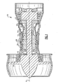
- FIG. 1 One example turbine engine 10 is shown schematically in Figure 1 .
- a fan section moves air and rotates about an axis A.
- a compressor section, a combustion section, and a turbine section are also centered on the axis A.
- Figure 1 is a highly schematic view, however, it does show the main components of the gas turbine engine. Further, while a particular type of gas turbine engine is illustrated in this figure, it should be understood that the claim scope extends to other types of gas turbine engines, including geared turbofan engines.
- the engine 10 includes a low spool 12 rotatable about an axis A.
- the low spool 12 is coupled to a fan 14, a low pressure compressor 16, and a low pressure turbine 24.
- a high spool 13 is arranged concentrically about the low spool 12.
- the high spool 13 is coupled to a high pressure compressor 17 and a high pressure turbine 22.
- a combustor 18 is arranged between the high pressure compressor 17 and the high pressure turbine 22.
- the high pressure turbine 22 and low pressure turbine 24 typically each include multiple turbine stages.
- a hub supports each stage on its respective spool. Multiple turbine blades are supported circumferentially on the hub.
- High pressure and low pressure turbine blades 20, 21 are shown schematically at the high pressure and low pressure turbines 22, 24.
- Stator vanes 26 are arranged between the different blade stages and may be of fixed or variable geometry.
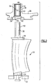
- stator vane 26 includes inner and outer trunnions 34, 30 respectively supported by an inner and outer case 32, 28.
- the outer case 28 (also shown schematically in Figure 1 ) includes a recess 38 that accommodates an outer platform 36 at a junction between the outer trunnion 30 and vane 26.
- the outer case 28 includes a boss 39 extending radially outward from the recess 38.
- the boss 39 has a bore 40 that receives a bushing 44 in a press-fit relationship.
- a chamfer 42 interconnects and extends between the recess 38 and bore 40 to facilitate installation of the bushing 44 into the outer case 28.
- an engine may include variable stator vanes arranged at multiple axial compressor stages 27a-27c.
- the bushing 44 is a unified construction of a non-metallic material.
- the non-metallic material extends radially from an inner diameter surface 52, which engages an outer trunnion outer diameter surface 50, to an outer diameter surface 54 that engages the bore 40.
- the bushing 44 is constructed from an electrographitic carbon.
- One type of electrographitic carbon is sintered to approximately 4,000°F (2204°C) during its formation. The electrographitic carbon can be brittle and subject to fracture if unsupported. To this end, it is desirable to install the bushing 44 into the bore 40 so that one or both of ends 46, 48 are supported within the bore 40.
- the bushing 44 is initially arranged at the inner diameter of the outer case 28 for installation.
- a tool typically employed for bushing installation can be used.
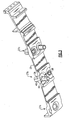
- an adapter 62 having a protrusion 66 is also provided to ensure the inner end 46 of the bushing 44 is installed to a desired radial depth 68, in one example, that does not leave the end 46 undesirably exposed and unsupported.
- the inner end 46 is generally flush with the intersection of the chamfer 42 and bore 40.
- a shoulder 70 of the adapter 62 seats against a wall 72 provided by a bottom of the recess 38. The inner end 46 is recessed from the wall 72.
- a sleeve 56 In operation, during installation, a sleeve 56 abuts the boss 39.
- a spacer 60 is arranged adjacent to the sleeve 56 opposite the boss 39.
- a threaded fastener 58 extends through the spacer 60, sleeve 56, bushing 44 and adapter 62.
- a nut 64 is secured to the fastener 58 near the adapter 62.
- the fastener 58 is tightened to draw the bushing 44 into the bore 40 in an interference fit.
- the shoulder 70 seats against the wall 72 thereby ensuring that the bushing 44 has been inserted into the bore 40 to the desired radial depth 68, thus ensuring adequate support to prevent damage.
- other installation tooling arrangements may be used.
Landscapes
- Engineering & Computer Science (AREA)
- Mechanical Engineering (AREA)
- General Engineering & Computer Science (AREA)
- Structures Of Non-Positive Displacement Pumps (AREA)
- Turbine Rotor Nozzle Sealing (AREA)
- Control Of Turbines (AREA)
Applications Claiming Priority (1)
| Application Number | Priority Date | Filing Date | Title |
|---|---|---|---|
| US11/733,242 US9353643B2 (en) | 2007-04-10 | 2007-04-10 | Variable stator vane assembly for a turbine engine |
Publications (4)
| Publication Number | Publication Date |
|---|---|
| EP1980721A2 true EP1980721A2 (fr) | 2008-10-15 |
| EP1980721A3 EP1980721A3 (fr) | 2011-10-05 |
| EP1980721B1 EP1980721B1 (fr) | 2013-10-30 |
| EP1980721B2 EP1980721B2 (fr) | 2018-02-21 |
Family
ID=39415401
Family Applications (1)
| Application Number | Title | Priority Date | Filing Date |
|---|---|---|---|
| EP08251043.9A Active EP1980721B2 (fr) | 2007-04-10 | 2008-03-25 | Ensemble d'aube de stator orientable pour moteur de turbine |
Country Status (2)
| Country | Link |
|---|---|
| US (1) | US9353643B2 (fr) |
| EP (1) | EP1980721B2 (fr) |
Cited By (1)
| Publication number | Priority date | Publication date | Assignee | Title |
|---|---|---|---|---|
| EP3467262A3 (fr) * | 2014-09-12 | 2019-05-22 | Honeywell International Inc. | Aubes de stator variables et procédé permettant de minimiser les fuites de paroi terminale avec ceux-ci |
Families Citing this family (20)
| Publication number | Priority date | Publication date | Assignee | Title |
|---|---|---|---|---|
| JP2008301624A (ja) * | 2007-05-31 | 2008-12-11 | Fujitsu Ltd | 流体軸受モータ、流体軸受式ディスク装置、及び流体軸受の製造方法 |
| US9650905B2 (en) * | 2012-08-28 | 2017-05-16 | United Technologies Corporation | Singlet vane cluster assembly |
| US9228438B2 (en) | 2012-12-18 | 2016-01-05 | United Technologies Corporation | Variable vane having body formed of first material and trunnion formed of second material |
| US9638212B2 (en) * | 2013-12-19 | 2017-05-02 | Pratt & Whitney Canada Corp. | Compressor variable vane assembly |
| DE102014223975A1 (de) * | 2014-11-25 | 2016-05-25 | MTU Aero Engines AG | Leitschaufelkranz und Strömungsmaschine |
| ES2797733T3 (es) * | 2016-03-16 | 2020-12-03 | MTU Aero Engines AG | Paleta guía ajustable para turbina, turbina y método de fabricación |
| DE102016215807A1 (de) * | 2016-08-23 | 2018-03-01 | MTU Aero Engines AG | Innenring für einen Leitschaufelkranz einer Strömungsmaschine |
| DE102017109952A1 (de) * | 2017-05-09 | 2018-11-15 | Rolls-Royce Deutschland Ltd & Co Kg | Rotorvorrichtung einer Strömungsmaschine |
| DE102018210601A1 (de) * | 2018-06-28 | 2020-01-02 | MTU Aero Engines AG | Segmentring zur montage in einer strömungsmaschine |
| US10830063B2 (en) * | 2018-07-20 | 2020-11-10 | Rolls-Royce North American Technologies Inc. | Turbine vane assembly with ceramic matrix composite components |
| FR3085420B1 (fr) | 2018-09-04 | 2020-11-13 | Safran Aircraft Engines | Disque de rotor avec arret axial des aubes, ensemble d'un disque et d'un anneau et turbomachine |
| US10711621B1 (en) | 2019-02-01 | 2020-07-14 | Rolls-Royce Plc | Turbine vane assembly with ceramic matrix composite components and temperature management features |
| US10767495B2 (en) | 2019-02-01 | 2020-09-08 | Rolls-Royce Plc | Turbine vane assembly with cooling feature |
| FR3092865B1 (fr) * | 2019-02-19 | 2021-01-29 | Safran Aircraft Engines | Disque de rotor avec arret axial des aubes, ensemble d’un disque et d’un anneau et turbomachine |
| US11346235B2 (en) * | 2019-06-04 | 2022-05-31 | Raytheon Technologies Corporation | Bushing for variable vane in a gas turbine engine |
| US11834966B1 (en) | 2022-12-30 | 2023-12-05 | Rolls-Royce North American Technologies Inc. | Systems and methods for multi-dimensional variable vane stage rigging utilizing adjustable alignment mechanisms |
| US11982193B1 (en) | 2022-12-30 | 2024-05-14 | Rolls-Royce North American Technologies Inc. | Systems and methods for multi-dimensional variable vane stage rigging utilizing adjustable inclined mechanisms |
| US12146415B2 (en) | 2022-12-30 | 2024-11-19 | Rolls-Royce North American Technologies Inc. | Systems and methods for multi-dimensional variable vane stage rigging utilizing adjustable bracket plates |
| US12000293B1 (en) | 2022-12-30 | 2024-06-04 | Rolls-Royce North American Technologies Inc. | Systems and methods for multi-dimensional variable vane stage rigging utilizing coupling mechanisms |
| BE1032726B1 (fr) * | 2024-06-28 | 2026-02-03 | Safran Aero Boosters | Ensemble redresseur pour compresseur basse pression de turbomachine |
Citations (1)
| Publication number | Priority date | Publication date | Assignee | Title |
|---|---|---|---|---|
| EP1400659A1 (fr) | 2002-09-18 | 2004-03-24 | General Electric Company | Méthode et appareil pour l'etanchification des aubes de guidage variables pour les turbines à gas |
Family Cites Families (32)
| Publication number | Priority date | Publication date | Assignee | Title |
|---|---|---|---|---|
| BE471940A (fr) † | 1946-03-20 | |||
| US3542484A (en) † | 1968-08-19 | 1970-11-24 | Gen Motors Corp | Variable vanes |
| US4025227A (en) * | 1975-06-30 | 1977-05-24 | United Technologies Corporation | Variable area turbine |
| US4808069A (en) * | 1986-07-03 | 1989-02-28 | The United States Of America As Represented By The Secretary Of The Air Force | Anti-rotation guide vane bushing |
| FR2608678B1 (fr) * | 1986-12-17 | 1991-02-08 | Snecma | Dispositif de commande d'aubes a calage variable de redresseur de turbomachine |
| US4792277A (en) † | 1987-07-08 | 1988-12-20 | United Technologies Corporation | Split shroud compressor |
| US4990056A (en) * | 1989-11-16 | 1991-02-05 | General Motors Corporation | Stator vane stage in axial flow compressor |
| US5031304A (en) * | 1989-12-14 | 1991-07-16 | The University Of Lowell | Compliance-matching assembly device |
| US5141394A (en) * | 1990-10-10 | 1992-08-25 | Westinghouse Electric Corp. | Apparatus and method for supporting a vane segment in a gas turbine |
| CA2082709A1 (fr) * | 1991-12-02 | 1993-06-03 | Srinivasan Venkatasubbu | Aubage de stator a incidence variable pour compresseur a ecoulement axial de turbomachine |
| US5492446A (en) * | 1994-12-15 | 1996-02-20 | General Electric Company | Self-aligning variable stator vane |
| US5622473A (en) * | 1995-11-17 | 1997-04-22 | General Electric Company | Variable stator vane assembly |
| FR2742799B1 (fr) * | 1995-12-20 | 1998-01-16 | Snecma | Palier d'extremite interne d'aube pivotante |
| FR2775731B1 (fr) * | 1998-03-05 | 2000-04-07 | Snecma | Etage circulaire d'aubes aux extremites interieures unies par un anneau de liaison |
| US6170990B1 (en) * | 1999-02-03 | 2001-01-09 | General Electric Company | Trunnion bushing |
| US6210106B1 (en) * | 1999-04-30 | 2001-04-03 | General Electric Company | Seal apparatus for gas turbine engine variable vane |
| FR2814205B1 (fr) * | 2000-09-18 | 2003-02-28 | Snecma Moteurs | Turbomachine a veine d'ecoulement ameliore |
| US6481960B2 (en) * | 2001-03-30 | 2002-11-19 | General Electric Co. | Variable gas turbine compressor vane structure with sintered-and-infiltrated bushing and washer bearings |
| US6682299B2 (en) * | 2001-11-15 | 2004-01-27 | General Electric Company | Variable stator vane support arrangement |
| FR2835562B1 (fr) * | 2002-02-07 | 2004-07-16 | Snecma Moteurs | Agencement de pivotement d'aube de stator dans une turbomachine |
| US7094022B2 (en) * | 2003-05-27 | 2006-08-22 | General Electric Company | Variable stator vane bushings and washers |
| US7163369B2 (en) * | 2003-05-27 | 2007-01-16 | General Electric Company | Variable stator vane bushings and washers |
| US20060029494A1 (en) * | 2003-05-27 | 2006-02-09 | General Electric Company | High temperature ceramic lubricant |
| US20050084190A1 (en) | 2003-10-15 | 2005-04-21 | Brooks Robert T. | Variable vane electro-graphitic bushing |
| EP1524413A2 (fr) | 2003-10-15 | 2005-04-20 | United Technologies Corporation | Manchon de palier en électro-graphite pour une aube variable |
| US7112039B2 (en) * | 2003-10-29 | 2006-09-26 | United Technologies Corporation | Variable vane electro-graphic thrust washer |
| FR2866058B1 (fr) * | 2004-02-05 | 2006-06-02 | Snecma Moteurs | Levier de commande du calage angulaire d'une aube dans une turbomachine |
| FR2882570B1 (fr) * | 2005-02-25 | 2007-04-13 | Snecma Moteurs Sa | Dipositif de commande d'aubes a calage variable dans une turbomachine |
| US7506514B2 (en) † | 2005-06-30 | 2009-03-24 | United Technologies Corporation | Augmentor fuel conduit bushing |
| DE102005040574A1 (de) * | 2005-08-26 | 2007-03-15 | Rolls-Royce Deutschland Ltd & Co Kg | Spaltkontrollvorrichtung für eine Gasturbine |
| FR2890707B1 (fr) * | 2005-09-14 | 2007-12-14 | Snecma | Douille pour pivot d'aube a angle de calage variable pour turbomachine |
| FR2896012B1 (fr) * | 2006-01-06 | 2008-04-04 | Snecma Sa | Dispositif anti-usure pour pivot de guidage d'aube a angle de calage variable de compresseur de turbomachine |
-
2007
- 2007-04-10 US US11/733,242 patent/US9353643B2/en active Active
-
2008
- 2008-03-25 EP EP08251043.9A patent/EP1980721B2/fr active Active
Patent Citations (1)
| Publication number | Priority date | Publication date | Assignee | Title |
|---|---|---|---|---|
| EP1400659A1 (fr) | 2002-09-18 | 2004-03-24 | General Electric Company | Méthode et appareil pour l'etanchification des aubes de guidage variables pour les turbines à gas |
Cited By (2)
| Publication number | Priority date | Publication date | Assignee | Title |
|---|---|---|---|---|
| EP3467262A3 (fr) * | 2014-09-12 | 2019-05-22 | Honeywell International Inc. | Aubes de stator variables et procédé permettant de minimiser les fuites de paroi terminale avec ceux-ci |
| US10527060B2 (en) | 2014-09-12 | 2020-01-07 | Honeywell International Inc. | Variable stator vane assemblies and variable stator vanes thereof having a locally swept leading edge and methods for minimizing endwall leakage therewith |
Also Published As
| Publication number | Publication date |
|---|---|
| US9353643B2 (en) | 2016-05-31 |
| EP1980721A3 (fr) | 2011-10-05 |
| EP1980721B2 (fr) | 2018-02-21 |
| EP1980721B1 (fr) | 2013-10-30 |
| US20090317241A1 (en) | 2009-12-24 |
Similar Documents
| Publication | Publication Date | Title |
|---|---|---|
| EP1980721B1 (fr) | Ensemble d'aube de stator orientable pour moteur de turbine à gaz | |
| EP1967718B1 (fr) | Virole pour turbine à gaz ayant des aubes de guidage à calage variable | |
| CN102418731B (zh) | 用于涡轮压缩机的可变叶片组件的连接螺栓 | |
| CN1760510B (zh) | 燃气涡轮发动机和用于燃气涡轮发动机的可变叶片组件 | |
| CN102418712B (zh) | 用于涡轮压缩机的可变静叶组件 | |
| US8215910B2 (en) | Aircraft turbomachine fan comprising a balancing flange concealed by the inlet cone | |
| EP1805398B1 (fr) | Turbochargeur a caracteristiques d'equilibrage | |
| EP1813782B1 (fr) | Turbo-Surpresseur | |
| EP1681473B1 (fr) | Roue de compresseur | |
| EP0298894A1 (fr) | Compresseur à virole divisée | |
| US20030170115A1 (en) | Variable stator vane support arrangement | |
| US8870533B2 (en) | Assembly for aligning an inner shell of a turbine casing | |
| EP1992785A2 (fr) | Turbine à vapeur | |
| US6571563B2 (en) | Gas turbine engine with offset shroud | |
| JP2007231934A (ja) | 可変ノズル付きターボチャージャ | |
| EP3592982B1 (fr) | Agencement de palier pour un arbre de transmission d'une turbomachine, et turbomachine équipée d'un tel agencement de palier | |
| US8932021B2 (en) | Fan rotor for air cycle machine | |
| EP1413764A2 (fr) | Assemblage de roue de compresseur | |
| EP2549060B1 (fr) | Verrouillage d'aubes dans une rainure de fixation tangentielle d'un rotor | |
| JP5638696B2 (ja) | コンプレッサおよびこれに関連したガスタービン | |
| CN107995941A (zh) | 轴承组件组件 | |
| EP3628823B1 (fr) | Joint d'étanchéité | |
| US20120156021A1 (en) | Fan rotor ring for an air cycle machine | |
| US10794219B2 (en) | Axial case ring to maximize thrust bushing contact area of variable vane | |
| US20180058231A1 (en) | Inner ring for an annular guide vane assembly of a turbomachine |
Legal Events
| Date | Code | Title | Description |
|---|---|---|---|
| PUAI | Public reference made under article 153(3) epc to a published international application that has entered the european phase |
Free format text: ORIGINAL CODE: 0009012 |
|
| AK | Designated contracting states |
Kind code of ref document: A2 Designated state(s): AT BE BG CH CY CZ DE DK EE ES FI FR GB GR HR HU IE IS IT LI LT LU LV MC MT NL NO PL PT RO SE SI SK TR |
|
| AX | Request for extension of the european patent |
Extension state: AL BA MK RS |
|
| PUAL | Search report despatched |
Free format text: ORIGINAL CODE: 0009013 |
|
| AK | Designated contracting states |
Kind code of ref document: A3 Designated state(s): AT BE BG CH CY CZ DE DK EE ES FI FR GB GR HR HU IE IS IT LI LT LU LV MC MT NL NO PL PT RO SE SI SK TR |
|
| AX | Request for extension of the european patent |
Extension state: AL BA MK RS |
|
| RIC1 | Information provided on ipc code assigned before grant |
Ipc: F01D 17/16 20060101AFI20110831BHEP |
|
| 17P | Request for examination filed |
Effective date: 20120330 |
|
| AKX | Designation fees paid |
Designated state(s): DE GB |
|
| GRAP | Despatch of communication of intention to grant a patent |
Free format text: ORIGINAL CODE: EPIDOSNIGR1 |
|
| INTG | Intention to grant announced |
Effective date: 20130425 |
|
| GRAS | Grant fee paid |
Free format text: ORIGINAL CODE: EPIDOSNIGR3 |
|
| GRAA | (expected) grant |
Free format text: ORIGINAL CODE: 0009210 |
|
| AK | Designated contracting states |
Kind code of ref document: B1 Designated state(s): DE GB |
|
| REG | Reference to a national code |
Ref country code: GB Ref legal event code: FG4D |
|
| REG | Reference to a national code |
Ref country code: DE Ref legal event code: R096 Ref document number: 602008028406 Country of ref document: DE Effective date: 20131224 |
|
| REG | Reference to a national code |
Ref country code: DE Ref legal event code: R026 Ref document number: 602008028406 Country of ref document: DE |
|
| PLBI | Opposition filed |
Free format text: ORIGINAL CODE: 0009260 |
|
| 26 | Opposition filed |
Opponent name: SIEMENS AKTIENGESELLSCHAFT Effective date: 20140728 |
|
| PLAX | Notice of opposition and request to file observation + time limit sent |
Free format text: ORIGINAL CODE: EPIDOSNOBS2 |
|
| REG | Reference to a national code |
Ref country code: DE Ref legal event code: R026 Ref document number: 602008028406 Country of ref document: DE Effective date: 20140728 |
|
| PLAF | Information modified related to communication of a notice of opposition and request to file observations + time limit |
Free format text: ORIGINAL CODE: EPIDOSCOBS2 |
|
| PLAB | Opposition data, opponent's data or that of the opponent's representative modified |
Free format text: ORIGINAL CODE: 0009299OPPO |
|
| R26 | Opposition filed (corrected) |
Opponent name: SIEMENS AKTIENGESELLSCHAFT Effective date: 20140728 |
|
| PLBB | Reply of patent proprietor to notice(s) of opposition received |
Free format text: ORIGINAL CODE: EPIDOSNOBS3 |
|
| RAP2 | Party data changed (patent owner data changed or rights of a patent transferred) |
Owner name: UNITED TECHNOLOGIES CORPORATION |
|
| REG | Reference to a national code |
Ref country code: DE Ref legal event code: R082 Ref document number: 602008028406 Country of ref document: DE Representative=s name: SCHMITT-NILSON SCHRAUD WAIBEL WOHLFROM PATENTA, DE |
|
| REG | Reference to a national code |
Ref country code: DE Ref legal event code: R082 Ref document number: 602008028406 Country of ref document: DE Representative=s name: SCHMITT-NILSON SCHRAUD WAIBEL WOHLFROM PATENTA, DE Ref country code: DE Ref legal event code: R081 Ref document number: 602008028406 Country of ref document: DE Owner name: UNITED TECHNOLOGIES CORP. (N.D.GES.D. STAATES , US Free format text: FORMER OWNER: UNITED TECHNOLOGIES CORPORATION, HARTFORD, CONN., US |
|
| PLAB | Opposition data, opponent's data or that of the opponent's representative modified |
Free format text: ORIGINAL CODE: 0009299OPPO |
|
| R26 | Opposition filed (corrected) |
Opponent name: SIEMENS AKTIENGESELLSCHAFT Effective date: 20140728 |
|
| PUAH | Patent maintained in amended form |
Free format text: ORIGINAL CODE: 0009272 |
|
| STAA | Information on the status of an ep patent application or granted ep patent |
Free format text: STATUS: PATENT MAINTAINED AS AMENDED |
|
| 27A | Patent maintained in amended form |
Effective date: 20180221 |
|
| AK | Designated contracting states |
Kind code of ref document: B2 Designated state(s): DE GB |
|
| REG | Reference to a national code |
Ref country code: DE Ref legal event code: R102 Ref document number: 602008028406 Country of ref document: DE |
|
| REG | Reference to a national code |
Ref country code: DE Ref legal event code: R081 Ref document number: 602008028406 Country of ref document: DE Owner name: RAYTHEON TECHNOLOGIES CORPORATION (N.D.GES.D.S, US Free format text: FORMER OWNER: UNITED TECHNOLOGIES CORP. (N.D.GES.D. STAATES DELAWARE), FARMINGTON, CONN., US Ref country code: DE Ref legal event code: R081 Ref document number: 602008028406 Country of ref document: DE Owner name: RTX CORPORATION (N.D.GES.D. STAATES DELAWARE),, US Free format text: FORMER OWNER: UNITED TECHNOLOGIES CORP. (N.D.GES.D. STAATES DELAWARE), FARMINGTON, CONN., US |
|
| P01 | Opt-out of the competence of the unified patent court (upc) registered |
Effective date: 20230519 |
|
| REG | Reference to a national code |
Ref country code: DE Ref legal event code: R081 Ref document number: 602008028406 Country of ref document: DE Owner name: RTX CORPORATION (N.D.GES.D. STAATES DELAWARE),, US Free format text: FORMER OWNER: RAYTHEON TECHNOLOGIES CORPORATION (N.D.GES.D.STAATES DELAWARE), ARLINGTON, VA, US |
|
| PGFP | Annual fee paid to national office [announced via postgrant information from national office to epo] |
Ref country code: GB Payment date: 20260219 Year of fee payment: 19 |
|
| PGFP | Annual fee paid to national office [announced via postgrant information from national office to epo] |
Ref country code: DE Payment date: 20260219 Year of fee payment: 19 |