EP1980830A2 - Dispositif de pression comprenant un capteur de température contenu dans un boîtier courant - Google Patents
Dispositif de pression comprenant un capteur de température contenu dans un boîtier courant Download PDFInfo
- Publication number
- EP1980830A2 EP1980830A2 EP08003583A EP08003583A EP1980830A2 EP 1980830 A2 EP1980830 A2 EP 1980830A2 EP 08003583 A EP08003583 A EP 08003583A EP 08003583 A EP08003583 A EP 08003583A EP 1980830 A2 EP1980830 A2 EP 1980830A2
- Authority
- EP
- European Patent Office
- Prior art keywords
- pressure sensor
- sensor device
- temperature sensor
- resin
- sensor element
- Prior art date
- Legal status (The legal status is an assumption and is not a legal conclusion. Google has not performed a legal analysis and makes no representation as to the accuracy of the status listed.)
- Granted
Links
- 229920005989 resin Polymers 0.000 claims abstract description 83
- 239000011347 resin Substances 0.000 claims abstract description 83
- WABPQHHGFIMREM-UHFFFAOYSA-N lead(0) Chemical compound [Pb] WABPQHHGFIMREM-UHFFFAOYSA-N 0.000 claims abstract description 35
- 239000004020 conductor Substances 0.000 claims abstract description 32
- 238000002485 combustion reaction Methods 0.000 claims abstract description 5
- 229910001369 Brass Inorganic materials 0.000 claims description 3
- 229910000906 Bronze Inorganic materials 0.000 claims description 3
- OAICVXFJPJFONN-UHFFFAOYSA-N Phosphorus Chemical compound [P] OAICVXFJPJFONN-UHFFFAOYSA-N 0.000 claims description 3
- 239000010951 brass Substances 0.000 claims description 3
- 239000010974 bronze Substances 0.000 claims description 3
- KUNSUQLRTQLHQQ-UHFFFAOYSA-N copper tin Chemical compound [Cu].[Sn] KUNSUQLRTQLHQQ-UHFFFAOYSA-N 0.000 claims description 3
- 239000012530 fluid Substances 0.000 claims 2
- 230000000994 depressogenic effect Effects 0.000 description 9
- YCKRFDGAMUMZLT-UHFFFAOYSA-N Fluorine atom Chemical compound [F] YCKRFDGAMUMZLT-UHFFFAOYSA-N 0.000 description 6
- 238000005260 corrosion Methods 0.000 description 6
- 230000007797 corrosion Effects 0.000 description 6
- 229910052731 fluorine Inorganic materials 0.000 description 6
- 239000011737 fluorine Substances 0.000 description 6
- 239000000463 material Substances 0.000 description 6
- 239000000853 adhesive Substances 0.000 description 4
- 230000001070 adhesive effect Effects 0.000 description 4
- 238000000034 method Methods 0.000 description 4
- 238000003466 welding Methods 0.000 description 4
- 239000004734 Polyphenylene sulfide Substances 0.000 description 3
- 229920001971 elastomer Polymers 0.000 description 3
- 239000011521 glass Substances 0.000 description 3
- 229920001707 polybutylene terephthalate Polymers 0.000 description 3
- 229920000069 polyphenylene sulfide Polymers 0.000 description 3
- 239000000758 substrate Substances 0.000 description 3
- 239000004593 Epoxy Substances 0.000 description 2
- 239000003822 epoxy resin Substances 0.000 description 2
- PCHJSUWPFVWCPO-UHFFFAOYSA-N gold Chemical compound [Au] PCHJSUWPFVWCPO-UHFFFAOYSA-N 0.000 description 2
- 229910052737 gold Inorganic materials 0.000 description 2
- 239000010931 gold Substances 0.000 description 2
- 238000004519 manufacturing process Methods 0.000 description 2
- 238000000465 moulding Methods 0.000 description 2
- 229920000647 polyepoxide Polymers 0.000 description 2
- 239000004065 semiconductor Substances 0.000 description 2
- RYGMFSIKBFXOCR-UHFFFAOYSA-N Copper Chemical compound [Cu] RYGMFSIKBFXOCR-UHFFFAOYSA-N 0.000 description 1
- 239000002253 acid Substances 0.000 description 1
- 229910045601 alloy Inorganic materials 0.000 description 1
- 239000000956 alloy Substances 0.000 description 1
- XAGFODPZIPBFFR-UHFFFAOYSA-N aluminium Chemical compound [Al] XAGFODPZIPBFFR-UHFFFAOYSA-N 0.000 description 1
- 229910052782 aluminium Inorganic materials 0.000 description 1
- 238000011109 contamination Methods 0.000 description 1
- 229910052802 copper Inorganic materials 0.000 description 1
- 239000010949 copper Substances 0.000 description 1
- 230000001627 detrimental effect Effects 0.000 description 1
- 239000003779 heat-resistant material Substances 0.000 description 1
- 239000011810 insulating material Substances 0.000 description 1
- -1 polybutylene terephthalate Polymers 0.000 description 1
- 238000004382 potting Methods 0.000 description 1
- 229920002379 silicone rubber Polymers 0.000 description 1
- 239000004945 silicone rubber Substances 0.000 description 1
- 238000005476 soldering Methods 0.000 description 1
Images



Classifications
-
- G—PHYSICS
- G01—MEASURING; TESTING
- G01K—MEASURING TEMPERATURE; MEASURING QUANTITY OF HEAT; THERMALLY-SENSITIVE ELEMENTS NOT OTHERWISE PROVIDED FOR
- G01K1/00—Details of thermometers not specially adapted for particular types of thermometer
- G01K1/16—Special arrangements for conducting heat from the object to the sensitive element
- G01K1/18—Special arrangements for conducting heat from the object to the sensitive element for reducing thermal inertia
-
- G—PHYSICS
- G01—MEASURING; TESTING
- G01K—MEASURING TEMPERATURE; MEASURING QUANTITY OF HEAT; THERMALLY-SENSITIVE ELEMENTS NOT OTHERWISE PROVIDED FOR
- G01K13/00—Thermometers specially adapted for specific purposes
- G01K13/02—Thermometers specially adapted for specific purposes for measuring temperature of moving fluids or granular materials capable of flow
-
- G—PHYSICS
- G01—MEASURING; TESTING
- G01L—MEASURING FORCE, STRESS, TORQUE, WORK, MECHANICAL POWER, MECHANICAL EFFICIENCY, OR FLUID PRESSURE
- G01L19/00—Details of, or accessories for, apparatus for measuring steady or quasi-steady pressure of a fluent medium insofar as such details or accessories are not special to particular types of pressure gauges
- G01L19/0092—Pressure sensor associated with other sensors, e.g. for measuring acceleration or temperature
-
- G—PHYSICS
- G01—MEASURING; TESTING
- G01L—MEASURING FORCE, STRESS, TORQUE, WORK, MECHANICAL POWER, MECHANICAL EFFICIENCY, OR FLUID PRESSURE
- G01L23/00—Devices or apparatus for measuring or indicating or recording rapid changes, such as oscillations, in the pressure of steam, gas, or liquid; Indicators for determining work or energy of steam, internal-combustion, or other fluid-pressure engines from the condition of the working fluid
- G01L23/24—Devices or apparatus for measuring or indicating or recording rapid changes, such as oscillations, in the pressure of steam, gas, or liquid; Indicators for determining work or energy of steam, internal-combustion, or other fluid-pressure engines from the condition of the working fluid specially adapted for measuring pressure in inlet or exhaust ducts of internal-combustion engines
-
- G—PHYSICS
- G01—MEASURING; TESTING
- G01K—MEASURING TEMPERATURE; MEASURING QUANTITY OF HEAT; THERMALLY-SENSITIVE ELEMENTS NOT OTHERWISE PROVIDED FOR
- G01K2205/00—Application of thermometers in motors, e.g. of a vehicle
- G01K2205/02—Application of thermometers in motors, e.g. of a vehicle for measuring inlet gas temperature
Definitions
- the present invention relates to a pressure sensor device that includes a temperature sensor contained in a common housing, and especially to such a pressure sensor device in which a response speed of the temperature sensor is improved.
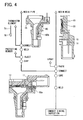
- a housing of the pressure sensor device 100 is composed of a resin head 10 and a resin pipe 30, both connected to each other. Terminals 11 for making electrical connections to an outside circuit are insert-molded in the resin head 10.
- a pressure sensor element 20 is mounted on a depressed portion 12 formed on the resin head 10 and electrically connected to one of the terminals 11.
- the resin pipe 30 includes an upper end forming a pressure-detecting chamber 16 and a lower end 31 for introducing air, a pressure of which is to be detected.
- an air passage 31a and a space 31b for mounting a temperature sensor 40 are formed in the resin pipe 30, an air passage 31a and a space 31b for mounting a temperature sensor 40 are formed.
- the air passage 31a and the space 31b are separated from each other by a separator 32.
- a temperature sensor element 40 is disposed close to the lower end 31 and electrically connected to a connecting portion 23 through a lead wire 24.
- the connecting portion 23 is connected to one of the terminals 11.
- the lead wire 24 is supported in the space 31b with a resilient cushion member 25 made of a material such as resin.
- the temperature sensor element 40 As the temperature sensor element 40, a thermistor having a diameter of about 3 mm is used.
- the lead wire 24 is made of a metallic wire having a diameter about 0.5 mm.
- the lead wire 24 extends from the connecting portion 23 in the resin head 10 to a bottom portion of the resin pipe 30.
- the pressure sensor 100 is mounted on an intake manifold of an automotive engine to detect air pressure and temperature taken into the engine. An amount of air taken into the engine is calculated based on the detected pressure and temperature.
- the temperature sensor element 40 has to be positioned close to the lower open end 31 of the resin pipe so that it is exposed to the intake air. For this purpose, the temperature sensor element 40 has to be supported by a thick and strong lead wire 24.
- the thick lead wire reduces a response speed of the temperature sensor and is detrimental to making the sensor device compact.
- the present invention has been made in view of the above-mentioned problem, and an object of the present invention is to provide an improved pressure sensor device having a temperature sensor contained in a common housing, which is compact and has a high response speed.
- the pressure sensor device includes a temperature sensor mounted on the same housing on which the pressure sensor is mounted.
- the pressure sensor detects, for example, an amount of air introduced into an intake manifold of an internal combustion engine based on detected pressure and temperature of the air.
- the pressure sensor device includes a housing composed of a resin head and a resin pipe, both being hermetically connected to each other.
- a pressure sensor element such as a piezoelectric element is mounted on a depressed portion formed in the resin head and electrically connected to a first terminal insert-molded in the resin head.
- the resin pipe for introducing intake air has a conductor bar embedded therein with its first end exposed in the resin head and its second end exposed to an air passage in the intake manifold.
- the first end is electrically connected to a second terminal insert-molded in the resin head.
- the second end is electrically connected to a lead wire of a temperature sensor element such as a thermistor.
- the temperature sensor element is directly exposed to the intake air in the intake manifold.
- a portion connecting the pressure sensor to the first terminal is covered with a protecting member such as fluorine gel, and a portion connecting the lead wire of the temperature sensor to the second end of the conductor bar is covered with protecting resin such as epoxy resin.
- a cross-section of the embedded portion of the conductor bar is formed in an L-shape or a T-shape to easily position the conductor bar in the molded resin of the resin pipe and to improve its mechanical strength.
- a diameter of the temperature sensor is preferably made smaller than 1.0 mm.
- a length of the lead wire of the temperature sensor is preferably made shorter than 30 mm, and its diameter is preferably made smaller than 0.3 mm.
- a response speed of the temperature sensor is improved by making the size of the temperature sensor and its lead wire small.
- a response speed of the temperature sensor is increased in a compact structure of the pressure sensor device.
- no structure for supporting the conductor bar is required since the conductor bar is embedded in the resin pipe.
- FIGS. 1-4 A pressure sensor device 101 shown in FIG. 1 is mounted on an intake manifold 90 of an internal combustion engine, as shown in FIG. 2 .
- Components that are similar to those of the conventional device shown in FIG. 5 have the same reference numbers.
- a pressure sensor element 20, a temperature sensor element 70 and other components are contained in a housing that is composed of a resin head 10 and a resin pipe 35, both made of a resin material. Terminals 11 including a first terminal and a second terminal are insert-molded in the resin head 10.
- a pressure sensor element 20 is mounted on a depressed portion 12 formed in the resin head 10 and electrically connected to the first terminal (one of the terminals 11). The pressure sensor element 20 detects pressure of air introduced into the housing.
- the resin head 10 is made of a resin material, such as polyphenylene sulfide (PPS), polybutylene terephthalate (PBT) or epoxy, by molding.
- the terminals 11 insert-molded in the resin head 10 are made of a conductive material such as copper or 42-alloy.
- One end of the first terminal is exposed outside in the depressed portion 12 and plated with gold, so that it functions as a boding pad to be electrically connected to the pressure sensor element 20 through bonding wires 14 made of, e.g., gold or aluminum.
- the other end of the first terminal is exposed to an opening 13 of the resin head 10 so that it is electrically connected to an outside circuit.
- the pressure sensor element 20 detects air pressure introduced into the housing and outputs electrical signals.
- the pressure sensor element 20 is composed of, for example, a glass substrate and a semiconductor sensor chip mounted on the glass substrate.
- the semiconductor sensor chip may be a known piezoelectric element having a diaphragm and a bridge circuit formed by diffused resistors.
- the pressure sensor element 20 is mounted on the depressed portion 12 by connecting its glass substrate to the depressed portion 12 with adhesive.
- the pressure sensor element 20 and the bonding wires 14 disposed in the depressed portion 12 are covered with a protecting member 15 made of an insulating material having a corrosion-resistant property, such as fluorine gel or fluorine rubber.
- the protecting member 15 has a two-layer structure.
- a lower layer is made of a material having a high elasticity modulus and a corrosion-resistant property, such as fluorine rubber, thereby to suppress generation of bubbles from a boundary between the resin head 10 and the first terminal.
- An upper layer is made of a low elasticity modulus and a corrosion-resistant property, such as fluorine gel or flurorosilicone gel, thereby to alleviate stress imposed on the pressure sensor element 20 and bonding wires 14.
- the resin pipe 35 is made of the same heat-resistant material as the resin head 10, such as PBT or PPS, by molding.
- the resin pipe 35 has a first opening 34a that is connected to the resin head 10, a pipe portion 34 and a second opening 34b from which air is introduced.
- An outer periphery of the first opening 34a is hermetically connected to the resin head 40 with adhesive 17 having high elasticity and a corrosion-resistant property, such as hard epoxy, forming a pressure-detecting chamber between the resin head 10 and the resin pipe 35.
- a temperature sensor element 70 such as a known thermistor element is positioned closed to the second opening 34b so that it is directly exposed to the air introduced into the housing.
- An o-ring 33 is connected to an outer periphery of the pipe portion 34, so that the pressure sensor device 101 is hermetically connected to an intake manifold 90, as shown in FIG. 2 .
- a conductor bar 60 made of a material such as brass or phosphor bronze is embedded in the resin pipe 35 with a first end 60a and a second end 60b exposed outside of the resin pipe 35.
- the second end 60b is electrically connected to a lead wire 71 of the temperature sensor element 70 by soldering, welding or staking.
- the first end 60a is electrically connected to a second terminal (one of the terminals 11) by welding.
- the conductor bar 60 is used to electrically connect the temperature sensor element 70 which is far apart from the second terminal disposed in the opening 13 of the resin head 10.
- the lead wire 71 of the temperature sensor element 70 can be made thin and short by using the conductor bar 60 thereby to improve a response speed of the temperature sensor element 70.
- FIGS. 3A, 3B and 3C Cross-sectional shapes of the conductor bar 60 at an embedded portion (taken along line III-III shown in FIG. 1 ) are shown in FIGS. 3A, 3B and 3C , a flat shape in FIG. 3A , an L-shape in FIG. 3B and a T-shape in FIG. 3C .
- a conductive material such as brass or phosphor bronze, which is strong and inexpensive.
- a portion connecting the second end 60b of the conductor bar 60 to the lead wire 71 of the temperature sensor element 70 is covered with a protecting resin 36 formed by potting or the like, as shown in FIG. 1 .
- the protecting resin 36 is made of an acid-resistant and corrosion-resistant material such as epoxy resin, fluorine rubber or silicone rubber.
- the connecting portion covered with the protecting resin 36 is positioned close to the temperature sensor element 70 to make the lead wire 71 as short as possible. Accordingly, the protecting resin 36 is exposed to an air passage in the intake manifold 90, as shown in FIG. 2 .
- the connecting portion is covered with the protecting resin 36, it is protected from corrosion and contamination. Further, the connecting portion is prevented from electrical leakage due to humid air.
- the lead wire 71 can be made thin and short, compared with that of the conventional device.
- the temperature sensor element 70 that is compact and light can be used. Therefore, a response speed of the temperature sensor element can be increased, while making the pressure sensor device 101 compact.
- an inexpensive and compact thermistor is used as the temperature sensor element 70.
- a thermistor having a diameter of 1.0 mm or less is used (though the size of temperature sensor element 70 shown in FIG. 1 is relatively large).
- the lead wire 71 having a diameter of 0.3 mm or less is also preferable. It is preferable to make the length of the lead wire 71 longer than 15 mm to make easy its connecting process. It is preferable to make the length of the lead wire 71 shorter than 30 mm to secure a sufficient strength against vibrations.
- the connecting portion between the conductor bar 60 and the lead wire 71 is positioned at a point, a distance to which from a tip (a bottom) of the resin pipe 35 does not exceed half a length of the resin pipe 35.
- a length of the lead wire 71 exposed outside of the resin pipe 35 is preferably set to a length not exceeding 10 mm. If that length were too long, the temperature sensor 70 would not be sufficiently held by the lead wire 71.
- a manufacturing process of the pressure sensor device 101 will be briefly explained with reference to FIG. 4 .
- the resin head 10 and the resin pipe 35 are separately made.
- the terminals 11 are insert-molded together with the main body of the resin head 10.
- the pressure sensor element 20 is mounted on the depressed portion 12 of the resin head 10 and connected thereto with adhesive.
- the pressure sensor element 20 is electrically connected to the terminal 11 through bonding wires 14.
- the depressed portion 12 is covered with the protecting member 15, and thereafter, the protecting member 15 is cured.
- the conductor bar 60 is insert-molded together with the main body of the resin pipe 35.
- the lead wire 71 of the temperature sensor element 70 is connected to the second end 60b of the conductor bar 60 by resistance welding or the like.
- the portion connecting the conductor bar 60 to the lead wire 71 is covered with the protecting resin 36, and thereafter the protecting resin 36 is hardened.
- the resin pipe 35 is hermetically connected to the resin head 10 with adhesive 17.
- the first end 60a of the conductor bar 60 is electrically connected to the second terminal by resistance welding or the like.
- the lead wire 71 of the temperature sensor element 70 is connected to the terminal through the embedded conductor bar 60, the lead wire 71 can be made thin and short, while making the temperature sensor element 70 compact. Therefore, the temperature sensor element 70 quickly responses to changes in temperature. Since the resin head 10 and the resin pipe 35 are separately formed, each of them can be standardized. Various types of the pressure sensor devices 101 can be made by assembling various types of the pressure sensor elements 20 and the temperature sensor elements 70 to the standardized resin head 10 and the resin pipe 35. An amount of air is accurately calculated based on the detected air pressure and the detected air temperature. Since the pressure sensor device 101 including the temperature sensor is compact, it is easily mounted on an intake manifold of an internal combustion engine.
Landscapes
- Physics & Mathematics (AREA)
- General Physics & Mathematics (AREA)
- Chemical & Material Sciences (AREA)
- Engineering & Computer Science (AREA)
- Combustion & Propulsion (AREA)
- Analytical Chemistry (AREA)
- Measuring Fluid Pressure (AREA)
- Measuring Temperature Or Quantity Of Heat (AREA)
Applications Claiming Priority (1)
| Application Number | Priority Date | Filing Date | Title |
|---|---|---|---|
| JP2007106185A JP2008261796A (ja) | 2007-04-13 | 2007-04-13 | 温度センサ一体型圧力センサ装置 |
Publications (3)
| Publication Number | Publication Date |
|---|---|
| EP1980830A2 true EP1980830A2 (fr) | 2008-10-15 |
| EP1980830A3 EP1980830A3 (fr) | 2010-09-01 |
| EP1980830B1 EP1980830B1 (fr) | 2016-04-13 |
Family
ID=39642666
Family Applications (1)
| Application Number | Title | Priority Date | Filing Date |
|---|---|---|---|
| EP08003583.5A Ceased EP1980830B1 (fr) | 2007-04-13 | 2008-02-27 | Dispositif de pression comprenant un capteur de température contenu dans un boîtier courant |
Country Status (4)
| Country | Link |
|---|---|
| US (1) | US7690262B2 (fr) |
| EP (1) | EP1980830B1 (fr) |
| JP (1) | JP2008261796A (fr) |
| CN (1) | CN101285726B (fr) |
Cited By (4)
| Publication number | Priority date | Publication date | Assignee | Title |
|---|---|---|---|---|
| US8733188B2 (en) | 2010-08-27 | 2014-05-27 | General Electric Company | Apparatus for mounting pipe sensors |
| US9606010B2 (en) | 2013-05-16 | 2017-03-28 | Robert Bosch Gmbh | Device for measuring a pressure and a temperature of a fluid medium flowing in a duct |
| AT518125A1 (de) * | 2015-11-16 | 2017-07-15 | Melecs Ews Gmbh & Co Kg | Gehäusedeckel für eine elektrische Maschine |
| IT202000012541A1 (it) * | 2020-06-11 | 2021-12-11 | Damino Giuseppe | dispositivo per la misura di variabili ambientali |
Families Citing this family (33)
| Publication number | Priority date | Publication date | Assignee | Title |
|---|---|---|---|---|
| JP5266438B2 (ja) * | 2007-03-19 | 2013-08-21 | コンティ テミック マイクロエレクトロニック ゲゼルシャフト ミット ベシュレンクテル ハフツング | センサ装置 |
| ITTO20080483A1 (it) * | 2008-06-19 | 2009-12-20 | Eltek Spa | Dispositivo sensore di pressione |
| ITTO20080484A1 (it) * | 2008-06-19 | 2009-12-20 | Eltek Spa | Dispositivo sensore di pressione |
| DE102008002682B4 (de) * | 2008-06-26 | 2020-01-30 | Robert Bosch Gmbh | Vorrichtung zur Erfassung des Drucks und der Temperatur in einem Saugrohr einer Brennkraftmaschine |
| KR101119235B1 (ko) | 2008-07-04 | 2012-03-21 | 가부시키가이샤 아루박 | 태양 전지 셀의 제조 방법 및 태양 전지 셀 |
| JP5394292B2 (ja) * | 2010-03-12 | 2014-01-22 | 東京エレクトロン株式会社 | 縦型熱処理装置および圧力検知システムと温度センサの組合体 |
| DE102010015087B4 (de) * | 2010-04-15 | 2021-06-17 | Andreas Stihl Ag & Co. Kg | Handgeführtes Arbeitsgerät mit Drucksensor und Temperatursensor |
| EP2434619B1 (fr) * | 2010-09-22 | 2018-11-14 | General Electric Technology GmbH | Agencement d'extrémités de barres conductrices |
| JP5557767B2 (ja) * | 2011-02-09 | 2014-07-23 | 日立オートモティブシステムズ株式会社 | センサの構造 |
| DE102012208054A1 (de) * | 2012-05-14 | 2013-11-14 | Continental Automotive Gmbh | Sauerstoffsensor und diesen aufweisende Brennkraftmaschine |
| DE102012223014A1 (de) * | 2012-12-13 | 2014-06-18 | Robert Bosch Gmbh | Vorrichtung zur Erfassung des Drucks und der Temperatur eines Mediums |
| DE212014000016U1 (de) * | 2013-02-18 | 2015-08-11 | Illinois Tool Works Inc. | Motorkrümmer-Sensoranordnung |
| US9593984B2 (en) | 2013-05-13 | 2017-03-14 | Emerson Electric Co. | Sensor probe |
| DE102013226236A1 (de) * | 2013-12-17 | 2015-06-18 | Robert Bosch Gmbh | Elektrische Baugruppe |
| JP6372148B2 (ja) * | 2014-04-23 | 2018-08-15 | 株式会社デンソー | 半導体装置 |
| MY165599A (en) * | 2014-10-03 | 2018-04-16 | Tlv Co Ltd | Sensor device |
| CN105181229B (zh) * | 2015-09-24 | 2018-04-24 | 浙江比华丽电子科技有限公司 | 用于太阳能热水器上的压力传感器 |
| WO2017095619A1 (fr) * | 2015-12-01 | 2017-06-08 | Maxim Integrated Products, Inc. | Systèmes et procédés de correction de décalage entre la température d'un capteur et la température ambiante d'un gaz |
| JP6076530B1 (ja) * | 2016-04-06 | 2017-02-08 | 三菱電機株式会社 | 温度センサ複合型半導体圧力センサ装置 |
| KR101766144B1 (ko) * | 2016-05-31 | 2017-08-08 | 현대자동차주식회사 | 온도센서 일체형 압력센서 |
| CN106840459A (zh) * | 2017-03-24 | 2017-06-13 | 北京航空航天大学 | 一种十孔总温测量探针 |
| CN106989839A (zh) * | 2017-03-24 | 2017-07-28 | 北京航空航天大学 | 一种两孔紧邻的总温探针 |
| CN106918409B (zh) * | 2017-03-27 | 2020-04-28 | 北京航空航天大学 | 一种多孔紧邻的总温探针 |
| CN106940230B (zh) * | 2017-03-28 | 2021-04-20 | 北京航空航天大学 | 一种九孔总温测量探针 |
| EP3617679B1 (fr) * | 2017-04-27 | 2021-06-09 | TLV Co., Ltd. | Dispositif capteur |
| US20180335360A1 (en) * | 2017-05-16 | 2018-11-22 | Honeywell International Inc. | Ported Pressure Sensor With No Internally Trapped Fluid |
| JP6891862B2 (ja) * | 2018-07-19 | 2021-06-18 | 株式会社デンソー | 圧力温度センサ |
| CN109406005A (zh) * | 2018-09-27 | 2019-03-01 | 国家能源投资集团有限责任公司 | 冷却塔出水温度测量装置及方法 |
| JP6656336B1 (ja) * | 2018-10-24 | 2020-03-04 | 三菱電機株式会社 | 温度センサ装置 |
| JP2021113722A (ja) * | 2020-01-17 | 2021-08-05 | 株式会社デンソー | 空気流量測定装置 |
| JP7260241B2 (ja) * | 2020-04-13 | 2023-04-18 | アルプスアルパイン株式会社 | 取付物取付状態の管理システム |
| CN114636510A (zh) * | 2020-12-15 | 2022-06-17 | 浙江三花汽车零部件有限公司 | 传感器组件以及阀装置 |
| JP7489747B2 (ja) * | 2021-01-15 | 2024-05-24 | 株式会社プロテリアル | 温度センサ付き配線部品 |
Citations (3)
| Publication number | Priority date | Publication date | Assignee | Title |
|---|---|---|---|---|
| JP2005274412A (ja) | 2004-03-25 | 2005-10-06 | Denso Corp | 温度センサ一体型圧力センサ装置 |
| JP2006194682A (ja) | 2005-01-12 | 2006-07-27 | Denso Corp | 温度センサ一体型圧力センサ装置 |
| JP2006194683A (ja) | 2005-01-12 | 2006-07-27 | Denso Corp | 温度センサ一体型圧力センサ装置 |
Family Cites Families (19)
| Publication number | Priority date | Publication date | Assignee | Title |
|---|---|---|---|---|
| JPH06132335A (ja) | 1992-10-16 | 1994-05-13 | Hitachi Cable Ltd | リードフレームインサート射出成形品の製造方法 |
| JPH07140013A (ja) | 1993-11-17 | 1995-06-02 | Nippondenso Co Ltd | 温度センサ |
| JPH095173A (ja) | 1995-06-22 | 1997-01-10 | Kurabe Ind Co Ltd | 温度検知器 |
| KR200145405Y1 (ko) * | 1996-11-05 | 1999-06-15 | 호우덴코 | 압력과 온도측정의 복합기능을 갖는 내연기관용 센서구조 |
| DE19711939A1 (de) * | 1997-03-21 | 1998-09-24 | Bosch Gmbh Robert | Vorrichtung zur Erfassung des Drucks und der Temperatur im Saugrohr einer Brennkraftmaschine |
| US6053049A (en) * | 1997-05-30 | 2000-04-25 | Motorola Inc. | Electrical device having atmospheric isolation |
| JP3404257B2 (ja) * | 1997-07-11 | 2003-05-06 | 三菱電機株式会社 | 圧力センサ装置 |
| DE19731420A1 (de) * | 1997-07-22 | 1999-01-28 | Bosch Gmbh Robert | Vorrichtung zur Erfassung des Drucks und der Temperatur im Saugrohr einer Brennkraftmaschine und Verfahren zu ihrer Herstellung |
| JP3319990B2 (ja) * | 1997-08-29 | 2002-09-03 | 三菱電機株式会社 | 圧力センサ装置 |
| JPH11185855A (ja) | 1997-12-17 | 1999-07-09 | Yazaki Corp | インサート樹脂成形品 |
| EP1096241A1 (fr) * | 1999-11-01 | 2001-05-02 | Delphi Technologies, Inc. | Capteur intégré de pression et de température pour fluide sous pression élevée |
| JP4320963B2 (ja) * | 2000-11-27 | 2009-08-26 | 株式会社デンソー | 圧力センサ |
| US7260992B2 (en) * | 2002-01-18 | 2007-08-28 | Hitachi, Ltd. | Pressure sensor, flowmeter electronic component, and method for manufacturing the same |
| JP3870918B2 (ja) * | 2002-10-23 | 2007-01-24 | 株式会社デンソー | 温度センサ一体型圧力センサ装置 |
| ITTO20030444A1 (it) * | 2003-06-13 | 2004-12-14 | Olivetti Jet Spa | Sensore di pressione a struttura integrata. |
| JP2005288934A (ja) * | 2004-04-01 | 2005-10-20 | Denso Corp | 樹脂材のレーザ溶着方法 |
| JP2005300456A (ja) * | 2004-04-15 | 2005-10-27 | Denso Corp | 温度センサ一体型圧力センサ装置およびその取り付け方法 |
| JP5044896B2 (ja) * | 2005-04-27 | 2012-10-10 | 富士電機株式会社 | 圧力検出装置 |
| US7478560B2 (en) * | 2007-03-08 | 2009-01-20 | Delphi Technologies, Inc. | Sensor apparatus responsive to pressure and temperature within a vessel |
-
2007
- 2007-04-13 JP JP2007106185A patent/JP2008261796A/ja active Pending
-
2008
- 2008-02-27 EP EP08003583.5A patent/EP1980830B1/fr not_active Ceased
- 2008-02-29 US US12/073,068 patent/US7690262B2/en not_active Expired - Fee Related
- 2008-03-13 CN CN2008100829419A patent/CN101285726B/zh not_active Expired - Fee Related
Patent Citations (3)
| Publication number | Priority date | Publication date | Assignee | Title |
|---|---|---|---|---|
| JP2005274412A (ja) | 2004-03-25 | 2005-10-06 | Denso Corp | 温度センサ一体型圧力センサ装置 |
| JP2006194682A (ja) | 2005-01-12 | 2006-07-27 | Denso Corp | 温度センサ一体型圧力センサ装置 |
| JP2006194683A (ja) | 2005-01-12 | 2006-07-27 | Denso Corp | 温度センサ一体型圧力センサ装置 |
Cited By (5)
| Publication number | Priority date | Publication date | Assignee | Title |
|---|---|---|---|---|
| US8733188B2 (en) | 2010-08-27 | 2014-05-27 | General Electric Company | Apparatus for mounting pipe sensors |
| US9606010B2 (en) | 2013-05-16 | 2017-03-28 | Robert Bosch Gmbh | Device for measuring a pressure and a temperature of a fluid medium flowing in a duct |
| AT518125A1 (de) * | 2015-11-16 | 2017-07-15 | Melecs Ews Gmbh & Co Kg | Gehäusedeckel für eine elektrische Maschine |
| AT518125B1 (de) * | 2015-11-16 | 2020-01-15 | Melecs Ews Gmbh & Co Kg | Gehäusedeckel für eine elektrische Maschine |
| IT202000012541A1 (it) * | 2020-06-11 | 2021-12-11 | Damino Giuseppe | dispositivo per la misura di variabili ambientali |
Also Published As
| Publication number | Publication date |
|---|---|
| US20080250862A1 (en) | 2008-10-16 |
| JP2008261796A (ja) | 2008-10-30 |
| EP1980830B1 (fr) | 2016-04-13 |
| US7690262B2 (en) | 2010-04-06 |
| CN101285726B (zh) | 2011-03-23 |
| EP1980830A3 (fr) | 2010-09-01 |
| CN101285726A (zh) | 2008-10-15 |
Similar Documents
| Publication | Publication Date | Title |
|---|---|---|
| US7690262B2 (en) | Pressure sensor device including temperature sensor contained in common housing | |
| US7216546B2 (en) | Pressure sensor having integrated temperature sensor | |
| KR100534560B1 (ko) | 온도센서 일체형 압력센서장치 | |
| US7004033B2 (en) | Pressure sensor contained in casing | |
| AU775608B2 (en) | Pressure sensor module | |
| KR20150083029A (ko) | 유체 매질의 온도 및 압력을 검출하기 위한 센서 | |
| JP2000510956A (ja) | 内燃機関の吸気管内の圧力と温度とを検出するための装置 | |
| JP4453729B2 (ja) | 圧力センサ | |
| JP2004028631A (ja) | 流量センサ | |
| US7216545B2 (en) | Acid-resistant pressure sensor | |
| JP2005300456A (ja) | 温度センサ一体型圧力センサ装置およびその取り付け方法 | |
| JP2006010426A (ja) | センサ装置およびその製造方法 | |
| US20060027025A1 (en) | Pressure sensor | |
| JP4821786B2 (ja) | 温度センサおよび温度センサ一体型圧力センサ | |
| JPWO2017212800A1 (ja) | 圧力センサ | |
| JP2006194683A (ja) | 温度センサ一体型圧力センサ装置 | |
| JP5655702B2 (ja) | 温度センサ、温度センサの製造方法及び温度センサ付圧力センサ | |
| JP4506478B2 (ja) | 圧力センサ | |
| JP2006194682A (ja) | 温度センサ一体型圧力センサ装置 | |
| JP4830669B2 (ja) | センサ装置およびその製造方法 | |
| JP4049129B2 (ja) | 圧力センサ装置 | |
| US6822873B2 (en) | Structure of electronic device providing decreased fatigue of wire | |
| JP2019027803A (ja) | 物理量センサ | |
| JP2006208087A (ja) | 圧力センサ | |
| JP2018185202A (ja) | 物理量センサ |
Legal Events
| Date | Code | Title | Description |
|---|---|---|---|
| PUAI | Public reference made under article 153(3) epc to a published international application that has entered the european phase |
Free format text: ORIGINAL CODE: 0009012 |
|
| AK | Designated contracting states |
Kind code of ref document: A2 Designated state(s): AT BE BG CH CY CZ DE DK EE ES FI FR GB GR HR HU IE IS IT LI LT LU LV MC MT NL NO PL PT RO SE SI SK TR |
|
| AX | Request for extension of the european patent |
Extension state: AL BA MK RS |
|
| PUAL | Search report despatched |
Free format text: ORIGINAL CODE: 0009013 |
|
| AK | Designated contracting states |
Kind code of ref document: A3 Designated state(s): AT BE BG CH CY CZ DE DK EE ES FI FR GB GR HR HU IE IS IT LI LT LU LV MC MT NL NO PL PT RO SE SI SK TR |
|
| AX | Request for extension of the european patent |
Extension state: AL BA MK RS |
|
| 17P | Request for examination filed |
Effective date: 20101227 |
|
| AKX | Designation fees paid |
Designated state(s): DE FR |
|
| 17Q | First examination report despatched |
Effective date: 20111209 |
|
| GRAP | Despatch of communication of intention to grant a patent |
Free format text: ORIGINAL CODE: EPIDOSNIGR1 |
|
| INTG | Intention to grant announced |
Effective date: 20150902 |
|
| GRAS | Grant fee paid |
Free format text: ORIGINAL CODE: EPIDOSNIGR3 |
|
| GRAA | (expected) grant |
Free format text: ORIGINAL CODE: 0009210 |
|
| AK | Designated contracting states |
Kind code of ref document: B1 Designated state(s): DE FR |
|
| REG | Reference to a national code |
Ref country code: DE Ref legal event code: R096 Ref document number: 602008043423 Country of ref document: DE |
|
| REG | Reference to a national code |
Ref country code: DE Ref legal event code: R097 Ref document number: 602008043423 Country of ref document: DE |
|
| PLBE | No opposition filed within time limit |
Free format text: ORIGINAL CODE: 0009261 |
|
| REG | Reference to a national code |
Ref country code: FR Ref legal event code: PLFP Year of fee payment: 10 |
|
| STAA | Information on the status of an ep patent application or granted ep patent |
Free format text: STATUS: NO OPPOSITION FILED WITHIN TIME LIMIT |
|
| 26N | No opposition filed |
Effective date: 20170116 |
|
| REG | Reference to a national code |
Ref country code: FR Ref legal event code: PLFP Year of fee payment: 11 |
|
| PGFP | Annual fee paid to national office [announced via postgrant information from national office to epo] |
Ref country code: DE Payment date: 20180219 Year of fee payment: 11 |
|
| PGFP | Annual fee paid to national office [announced via postgrant information from national office to epo] |
Ref country code: FR Payment date: 20180223 Year of fee payment: 11 |
|
| REG | Reference to a national code |
Ref country code: DE Ref legal event code: R119 Ref document number: 602008043423 Country of ref document: DE |
|
| PG25 | Lapsed in a contracting state [announced via postgrant information from national office to epo] |
Ref country code: DE Free format text: LAPSE BECAUSE OF NON-PAYMENT OF DUE FEES Effective date: 20190903 |
|
| PG25 | Lapsed in a contracting state [announced via postgrant information from national office to epo] |
Ref country code: FR Free format text: LAPSE BECAUSE OF NON-PAYMENT OF DUE FEES Effective date: 20190228 |