EP1982147B1 - Capteur d'angle de rotation et procédé pour déterminer la position angulaire absolue d'un corps effectuant plusieurs rotations - Google Patents
Capteur d'angle de rotation et procédé pour déterminer la position angulaire absolue d'un corps effectuant plusieurs rotations Download PDFInfo
- Publication number
- EP1982147B1 EP1982147B1 EP07722793A EP07722793A EP1982147B1 EP 1982147 B1 EP1982147 B1 EP 1982147B1 EP 07722793 A EP07722793 A EP 07722793A EP 07722793 A EP07722793 A EP 07722793A EP 1982147 B1 EP1982147 B1 EP 1982147B1
- Authority
- EP
- European Patent Office
- Prior art keywords
- angle
- beat
- sensor
- periods
- angular position
- Prior art date
- Legal status (The legal status is an assumption and is not a legal conclusion. Google has not performed a legal analysis and makes no representation as to the accuracy of the status listed.)
- Active
Links
Images
Classifications
-
- G—PHYSICS
- G01—MEASURING; TESTING
- G01D—MEASURING NOT SPECIALLY ADAPTED FOR A SPECIFIC VARIABLE; ARRANGEMENTS FOR MEASURING TWO OR MORE VARIABLES NOT COVERED IN A SINGLE OTHER SUBCLASS; TARIFF METERING APPARATUS; MEASURING OR TESTING NOT OTHERWISE PROVIDED FOR
- G01D5/00—Mechanical means for transferring the output of a sensing member; Means for converting the output of a sensing member to another variable where the form or nature of the sensing member does not constrain the means for converting; Transducers not specially adapted for a specific variable
- G01D5/12—Mechanical means for transferring the output of a sensing member; Means for converting the output of a sensing member to another variable where the form or nature of the sensing member does not constrain the means for converting; Transducers not specially adapted for a specific variable using electric or magnetic means
- G01D5/14—Mechanical means for transferring the output of a sensing member; Means for converting the output of a sensing member to another variable where the form or nature of the sensing member does not constrain the means for converting; Transducers not specially adapted for a specific variable using electric or magnetic means influencing the magnitude of a current or voltage
- G01D5/142—Mechanical means for transferring the output of a sensing member; Means for converting the output of a sensing member to another variable where the form or nature of the sensing member does not constrain the means for converting; Transducers not specially adapted for a specific variable using electric or magnetic means influencing the magnitude of a current or voltage using Hall-effect devices
- G01D5/145—Mechanical means for transferring the output of a sensing member; Means for converting the output of a sensing member to another variable where the form or nature of the sensing member does not constrain the means for converting; Transducers not specially adapted for a specific variable using electric or magnetic means influencing the magnitude of a current or voltage using Hall-effect devices influenced by the relative movement between the Hall device and magnetic fields
Definitions
- the invention relates to a rotation angle sensor for determining the absolute angular position of a rotatable body over several round body, such as a steering shaft of a motor vehicle, with two magnetically working measuring elements, each comprising a magnetic, compared to a sensor element rotationally driven and driven by the body donor element, the two Encoder elements for determining the beating angle resulting from the difference of the angle information of the donor elements are driven with a different gear ratio, which is designed so that within the angular range of the rotatable body extending over several rounds more than one barb angle period is included, and the absolute angular position of the donor elements is different in the beat angle periods. Furthermore, the invention relates to a method for determining the absolute angular position of such a rotation angle sensor.
- Rotation angle sensors are used to obtain angle information regarding the current angular position of a rotatably mounted body, such as a shaft. Such rotational angle sensors are used, inter alia, as steering angle sensors for detecting the angular position of the steering spindle of a motor vehicle.
- a steering angle sensors for example, optoelectronic working designed known in which an operatively connected to the steering shaft code disc carries the angle information. This code disc surrounds the steering spindle circumferentially in the radial direction and requires a certain radial extent, so that the necessary angle information can be accommodated on this. This applies in particular to those steering angle sensors with which the absolute angular position of the steering spindle is to be determined within its angular range extending over several rounds.
- two code wheels are driven by the rotatable body, for example the steering spindle.
- the code wheels each have an outer Sprocket on.
- the toothing of the code wheels engages in an outer sprocket having drive wheel of the steering shaft.
- the code wheels each have a magnetic encoder element whose magnetic field orientation is a measure of the rotational angle position of the code wheel.
- the two code wheels are driven with a different transmission ratio of the rotatable body associated drive wheel. Using the so-called vernier principle, the angular position of the rotatable body is determined within its angular range extending over several rounds.
- the code wheels have a smaller number of teeth than the rotatable body associated drive wheel.
- the reduction ratio is designed so that the code wheels are rotated n times 360 ° within the angular range extending over several rounds of the rotatable body, where n is greater than the number of rounds of the angle measuring range. For example, while the one code wheel is rotated completely nine times over the given angle measuring range of the rotatable body, the other code wheel is completely rotated about its own axis ten times over the same measuring range.
- the receiver elements are magneto-sensitive sensors, for example GMR, AMR or Hall sensors.
- the difference between the angle information of the two measuring elements results in a beating angle over the entire measuring range, which has the value 0 at one end of the angle measuring range and a value corresponding to the maximum output signal of the one measuring element at the other end of the angle measuring range of the rotational angle sensor.
- the beating angle extending over the entire angle measuring range has a constant slope.
- the beat angle is scaled and from this the angle information of the one measuring element associated with a code wheel is subtracted.
- the scaling of the beat angle is designed so that, after subtracting the angle information from the scaled beat angle, individual horizontally extending curve sections are created, each of which defines its own level. Each level defines one round of this code wheel, so that in this way the lap information required for the absolute angle determination can be obtained.
- such a rotation angle sensor has become known EP 0 877 916 A1 ,
- the angle information of the rotatable body, for example the steering spindle, obtained by means of such a rotational angle sensor is controlled by the wheel angle position in the context of a plausibility check in the case of steering angle sensors.
- the Radwinkel ein is again determined by the different wheel speed of the steered front wheels of the motor vehicle.
- the measurement inaccuracy of this wheel angle determination may be on the order of magnitude of the angle error that occurs in the mistaken choice of an adjacent round. As part of the plausibility check, this leads to the angle angle information obtained by the steering angle sensor.
- the measuring range of this sensor includes a plurality of beat angle periods, wherein the cyclic periods of the two encoder elements are selected so that the least common multiple of the cyclic periods is equal to a predetermined steering angle of an automobile. This leads to very different drive ratios for the two encoder elements and thus to very different rotational speeds.
- the rotation angle sensor according to the present invention has the advantage over this previously known sensor that very similar drive ratios can be selected for the two transmitter elements, so that comparatively low rotational speeds of both transmitter elements can be achieved. In addition to a simplified structure, this also results in a low noise development and the usability of a very simple and less prone to interference evaluation.
- the differently translated drive of the encoder elements which are suitably carried by code wheels, designed so that within the extending over several rounds Winkelmess Kunststoffes more than one beat angle period is included, so for example, this repeated several times periodically within the angle measuring range.
- the subdivision of the angle measuring range into a plurality of beat angle periods results in that the slope of the beat angle within each period corresponding to the number of beat angle periods provided within the angle measuring range is greater than for a single beat angle extending over the entire angle measuring range.
- the larger slope has the immediate result that the distance between the levels used for determining the lap, formed over the scaled beat angle of each other is correspondingly greater.
- the absolute angles of the transmitter elements differ from one another in the beat angle periods.
- the offset is, for example, 180 ° in the case of an angle measuring range with two beat angle periods, implying that the measuring range of a sensor element is 360 °. This angular displacement represents additional information from which the beat angle period can be uniquely determined.
- the code wheels carrying the transmitter elements each have a different number of teeth and can be driven by the different numbers of teeth of a drive wheel associated with the rotatable body, for example the steering spindle. It is possible that both code wheels are driven directly by the drive wheel or that a Coderad is driven by the drive wheel, while the second Coderad is driven by the first Coderad. The differences in the transmission ratio of the two driven Codezier is greater in the subject of this rotation angle sensor than in prior art rotation angle sensors.
- the rotatable body for example, the steering shaft, two different sized drive wheels with a correspondingly different number of teeth, engages in each of the ring gear of a Coderades.
- the diameter of the steering spindle is typically significantly larger than the diameter of the code wheels, so that therefore drive wheels with a different number of teeth can be readily arranged.
- the code wheels each carry an equal number of teeth and the steering spindle serving as a rotatable body has two drive wheels each having a different number of teeth, the difference in the number of teeth being between five and seven teeth.
- the code wheels themselves may also have a different number of teeth.
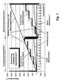
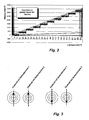
- FIGS. 1 and 2 Evaluation diagrams are shown with several evaluation curves.
- the signals reproduced in the diagrams are interference superimposed.
- the detected signals are thus noisy sensor signals.
- FIG. 1 In the diagram of FIG. 1 is plotted on the x-axis extending over several rounds of a steering shaft of a motor vehicle angular range. This is in the illustrated embodiment five rounds (1800 °).
- the angle of rotation sensor with which the absolute steering angle position of the steering spindle is to be determined is designed such that within this measuring range, a code wheel carrying a magnetic encoder element is rotated by 360 ° nine times.
- the output signal of this sensor element associated sensor element results in FIG. 1 illustrated lower sawtooth curve.
- the angular position of the code wheel can be determined unambiguously.
- the rotation angle sensor has another code wheel.
- the further code wheel with the further magnetic encoder element is indirectly or indirectly driven by the steering spindle in a differently squared manner in such a way that two beat angle periods are created within the angle measuring range.
- the beat angle is formed by subtracting the angle information signals generated by the encoder element of the one code wheel from those of the other code wheel.
- the beating angle has a constant slope in the two beating angle periods provided in the illustrated embodiment. About the beat angle required for the absolute angle determination of the steering shaft lap information of the codewheel whose waveform is in FIG. 1 is shown determined. For this purpose, the beat angle is scaled.
- the scaled beat angle subtracts the angle information obtained during a scan.
- FIG. 1 illustrated stepped step-like curve whose individual horizontal sections are labeled "level" in the context of these embodiments.
- the levels are different so that each round of the code wheel can be uniquely determined. Due to the slope of the beat angle, the jump height of adjacent levels is sufficiently high that even faulty plausibility check results could not question the result of the round so far that it could be located on an immediately adjacent level.
- the calculated angle signal is entered, which extends over the angle measuring range as a continuously rising curve. It can be seen that a unique angular position of the steering spindle serving as a rotatable body can be calculated on each angular position of the encoder elements as a function of its round.
- the scaling of the beat angle takes place such that, after subtracting the angle information obtained during the sampling, the individual levels of the level curve have a horizontal extension and thus a constant y value over their length.
- the absolute angle of the two encoder wheels supporting a magnetic encoder element is shifted by half the measurement range of a sensor element, resulting in the jump in the scaled beat angle curve and in the level curve.
- the immediate Levels adjacent to the jump point define the same round of code wheel. Due to the unambiguous determination of each round of the code wheel is also an unambiguous assignment of the angular position of the steering shaft with respect to that round in which the steering shaft is possible.
- FIG. 1 For distinguishing the evaluation diagram recorded with a rotation angle sensor according to the invention ( FIG. 1 ) with a corresponding evaluation diagram, recorded with a conventional rotation angle sensor, is one such. Diagram in FIG. 2 shown. Clearly visible in the evaluation diagram of the previously known rotation angle sensor is the significantly lower jump height between adjacent levels, which is only half as large as that of in FIG. 1 illustrated embodiment of the invention. The signal-to-noise ratio is significantly lower than in the case of the invention.
- FIG. 3 shows the absolute angular position of each of a magnetic encoder element, for example, a magnet-carrying code wheels of a trained as a steering angle sensor rotation angle sensor according to the invention, in the left portion of FIG. 3 in the starting position the in FIG. 1 the left beating angle period shown and in the right part of FIG Figure 3 in their position after passing through the first beating angle period and thus immediately behind in FIG. 1 shown jump point at the beginning of the second beat angle period.
- the offset to be designated offset of the absolute angle of the two code wheels in the two beat angle periods is 180 °, thus half the measuring range of a sensor element.
- the rotation angle sensor may also have more than two measuring elements.
Landscapes
- Physics & Mathematics (AREA)
- General Physics & Mathematics (AREA)
- Measurement Of Length, Angles, Or The Like Using Electric Or Magnetic Means (AREA)
- Transmission And Conversion Of Sensor Element Output (AREA)
- Control Of Position Or Direction (AREA)
Claims (7)
- Capteur d'angle de rotation pour la détermination de la position angulaire absolue d'un corps rotatif pouvant exécuter plusieurs tours, comme, par exemple, l'arbre de direction d'un véhicule automobile, avec deux éléments de mesure, fonctionnant magnétiquement, qui comprennent, chacun, un élément codeur magnétique, mû en rotation par rapport à un élément capteur et entraîné par ledit corps, les deux éléments codeurs étant, pour la détermination de l'angle de battement, qui résulte de la différence de l'information angulaire des éléments codeurs, entraînés avec un rapport de transmission différent, qui est calculé de sorte que plus d'une période de l'angle de battement soit contenue dans la plage de mesure d'angle du corps rotatif couvrant plusieurs tours, et que la position angulaire absolue des éléments codeurs soit différente dans les périodes de l'angle de battement, caractérisé en ce que la position angulaire absolue des éléments codeurs, dans des périodes d'angle de battement successives, est décalée de 1/néme de la plage de mesure d'un élément capteur, n étant le nombre des périodes de l'angle de battement comprises dans une plage de mesure d'angle.
- Capteur d'angle de rotation selon la revendication 1, caractérisé en ce que deux ou plusieurs périodes de l'angle de battement sont comprises dans la plage de mesure d'angle.
- Capteur d'angle de rotation selon l'une des revendications 1 et 2, caractérisé en ce que les éléments codeurs font chacun partie d'une roue code avec une jante dentée extérieure, qui est en relation avec une roue motrice du corps rotatif.
- Capteur d'angle de rotation selon la revendication 3, caractérisé en ce que les roues code présentent un nombre de dents différent.
- Capteur d'angle de rotation selon revendication 3 ou 4, caractérisé en ce que le corps rotatif porte une roue motrice avec une jante dentée extérieure, dans laquelle s'engagent les jantes dentées des roues code.
- Capteur d'angle de rotation selon revendication 3 ou 4, caractérisé en ce que le corps rotatif porte deux roues motrices, qui présentant chacune une jante dentée extérieure, mais présentent des nombres de dents différents, chaque roue code s'engrenant dans la denture d'une roue motrice.
- Procédé pour la détermination de la position angulaire absolue d'un corps rotatif, pouvant exécuter plusieurs tours, comme, par exemple, l'arbre de direction d'un véhicule automobile, avec deux éléments de mesure, fonctionnant magnétiquement, qui comprennent, chacun, un élément codeur magnétique, mû en rotation par rapport à un capteur de mesure et entraîné par ledit corps, les deux éléments codeurs étant entraînés avec un rapport de transmission différent, ledit procédé comprenant une détermination de l"angle de battement, en tant que différence de l'information angulaire des signaux de sortie des éléments de mesure, la plage de mesure, qui, s'étend sur plusieurs tours, étant divisée en plus d'une section de période de l'angle de battement, lesdites sections de périodes de l'angle de battement comprenant chacune une période d'angle de battement, caractérisé en ce que la position angulaire absolue des 'éléments codeurs, dans des périodes de l'angle de battement se succédant, est décalée de 1/n ème de la plage de mesure d'un élément capteur, n étant le nombre des périodes de l'angle de battement au sein d'une plage de mesure d'angle.
Applications Claiming Priority (2)
| Application Number | Priority Date | Filing Date | Title |
|---|---|---|---|
| DE102006006359A DE102006006359A1 (de) | 2006-02-11 | 2006-02-11 | Drehwinkelsensor sowie Verfahren zum Bestimmen der absoluten Winkelstellung eines über mehrere Runden drehbaren Körpers |
| PCT/EP2007/001126 WO2007090669A1 (fr) | 2006-02-11 | 2007-02-09 | Capteur d'angle de rotation et procédé pour déterminer la position angulaire absolue d'un corps effectuant plusieurs rotations |
Publications (2)
| Publication Number | Publication Date |
|---|---|
| EP1982147A1 EP1982147A1 (fr) | 2008-10-22 |
| EP1982147B1 true EP1982147B1 (fr) | 2009-12-16 |
Family
ID=37963621
Family Applications (1)
| Application Number | Title | Priority Date | Filing Date |
|---|---|---|---|
| EP07722793A Active EP1982147B1 (fr) | 2006-02-11 | 2007-02-09 | Capteur d'angle de rotation et procédé pour déterminer la position angulaire absolue d'un corps effectuant plusieurs rotations |
Country Status (8)
| Country | Link |
|---|---|
| US (1) | US7637020B2 (fr) |
| EP (1) | EP1982147B1 (fr) |
| JP (1) | JP2009526214A (fr) |
| CN (1) | CN101356422B (fr) |
| AT (1) | ATE452327T1 (fr) |
| DE (2) | DE102006006359A1 (fr) |
| ES (1) | ES2337740T3 (fr) |
| WO (1) | WO2007090669A1 (fr) |
Families Citing this family (22)
| Publication number | Priority date | Publication date | Assignee | Title |
|---|---|---|---|---|
| FR2899862B1 (fr) * | 2006-04-13 | 2009-06-05 | Siemens Vdo Automotive Sas | Procede et dispositif de mesure de la position angulaire, entre deux butees de braquage,d'un volant de direction d'un vehicule |
| DE102006023286A1 (de) * | 2006-05-18 | 2007-11-22 | Leopold Kostal Gmbh & Co. Kg | Winkelsensor |
| CN101376405B (zh) * | 2008-09-05 | 2010-06-02 | 卢灿光 | 一种旋转角度传感器 |
| DE102008063950A1 (de) | 2008-12-19 | 2010-06-24 | Leopold Kostal Gmbh & Co. Kg | Übertragungselement zur drehmomentübertragenden Verbindung zweier drehbarer Elemente miteinander |
| DE102008063951A1 (de) | 2008-12-19 | 2010-06-24 | Leopold Kostal Gmbh & Co. Kg | Winkelsensor |
| DE102009018893A1 (de) | 2009-04-24 | 2010-10-28 | Leopold Kostal Gmbh & Co. Kg | Winkelsensor |
| DE102009031176A1 (de) | 2009-06-29 | 2010-12-30 | Leopold Kostal Gmbh & Co. Kg | Winkelsensor |
| DE102010024782A1 (de) | 2010-06-23 | 2011-12-29 | Leopold Kostal Gmbh & Co. Kg | Winkelsensor |
| TWI500907B (zh) | 2011-01-07 | 2015-09-21 | Oriental Motor Co Ltd | 多圈旋轉絕對旋轉角之檢測裝置及該旋轉角之檢測方法 |
| DE102011106339B4 (de) | 2011-03-04 | 2012-12-06 | Auma Riester Gmbh & Co. Kg | Messvorrichtung zur Erfassung des Absolutdrehwinkels eines rotierenden Messobjekts |
| JP5545769B2 (ja) | 2011-07-12 | 2014-07-09 | オリエンタルモーター株式会社 | アブソリュート変位量を算出する装置及びその方法 |
| US20130090890A1 (en) | 2011-10-10 | 2013-04-11 | Advanced Sensor Technology Limited | Absolute position measuring device and method |
| JP5420624B2 (ja) * | 2011-11-14 | 2014-02-19 | オリエンタルモーター株式会社 | 多回転アブソリュート回転角検出装置及びアブソリュート回転角を検出する方法 |
| DE102012022869A1 (de) | 2012-11-21 | 2014-05-22 | Volkswagen Aktiengesellschaft | Lenkwinkelsensor und Vorrichtung zur kombinierten Erfassung von einem Winkel und einem Drehmoment |
| CN103063127B (zh) * | 2012-12-26 | 2015-08-19 | 万向钱潮(上海)汽车系统有限公司 | 编码磁阻结合式esp绝对式多圈角度传感器 |
| CN103528605B (zh) * | 2013-10-15 | 2015-11-11 | 北京航空航天大学 | 一种电容型绝对式旋转编码器 |
| EP3090921B1 (fr) * | 2015-02-19 | 2018-12-05 | NSK Ltd. | Appareil de détection d'angle de direction de véhicule, et appareil de direction à assistance électrique équipé de celui-ci |
| CN104634367B (zh) * | 2015-03-04 | 2017-06-13 | 哈尔滨工业大学 | 一种大中心孔结构的磁电式绝对位置传感器及测量绝对位置的方法 |
| US10436056B2 (en) | 2015-06-23 | 2019-10-08 | General Electric Company | Relative position measurement |
| CN106568984A (zh) * | 2016-10-20 | 2017-04-19 | 钟立朋 | 一种车速传感器 |
| EP3385678B1 (fr) | 2017-04-06 | 2021-07-28 | Melexis Technologies SA | Capteur de position de rotation |
| EP4276418B1 (fr) * | 2022-05-09 | 2025-08-13 | NM Numerical Modelling GmbH | Dispositif capteur et procédé pour déterminer une position angulaire relative entre les moitiés d'arbre d'un arbre rotatif |
Family Cites Families (17)
| Publication number | Priority date | Publication date | Assignee | Title |
|---|---|---|---|---|
| DE19506938A1 (de) * | 1995-02-28 | 1996-08-29 | Bosch Gmbh Robert | Verfahren und Vorrichtung zur Winkelmessung bei einem drehbaren Körper |
| DE19821467A1 (de) * | 1998-05-13 | 1999-11-18 | Thomas Klug | Zwei und mehrdimensionales Differenzengetriebe zur hochauflösenden absoluten Messung der Anzahl von Umdrehungen einer Welle |
| DE19855960A1 (de) * | 1998-12-04 | 2000-06-08 | Bosch Gmbh Robert | Vorrichtung und Verfahren zur Messung der Winkellage eines drehbaren Körpers |
| AU2001286223A1 (en) * | 2000-09-19 | 2002-04-02 | Honda Giken Kogyo Kabushiki Kaisha | Rotational position detector and motor equipped with rotational position detector |
| WO2002025217A1 (fr) | 2000-09-25 | 2002-03-28 | Kabushiki Kaisha Tokai Rika Denki Seisakusho | Detecteur d'angle tournant |
| DE10048911C1 (de) * | 2000-10-02 | 2002-04-25 | Ruf Electronics Gmbh | Verfahren und Vorrichtung zur Bestimmung der Absolutposition bei Weg- und Winkelgebern |
| WO2003036237A1 (fr) * | 2001-10-19 | 2003-05-01 | Kabushiki Kaisha Yaskawa Denki | Codeur de type a rotations multiples |
| JP4123761B2 (ja) * | 2001-11-15 | 2008-07-23 | 松下電器産業株式会社 | 回転角度検出装置 |
| DE10213224A1 (de) * | 2002-03-25 | 2003-10-16 | Delphi Tech Inc | Lenkstockmodul für ein Kraftfahrzeug |
| US6745116B2 (en) | 2002-09-24 | 2004-06-01 | Yazaki Corporation | Steering angle sensor for vehicle |
| JP4241012B2 (ja) * | 2002-11-25 | 2009-03-18 | パナソニック株式会社 | 回転角度検出装置 |
| JP2004191163A (ja) * | 2002-12-11 | 2004-07-08 | Matsushita Electric Ind Co Ltd | 回転角度検出装置 |
| JP2005003625A (ja) * | 2003-06-16 | 2005-01-06 | Matsushita Electric Ind Co Ltd | 回転角度検出装置 |
| JP2005031055A (ja) * | 2003-06-20 | 2005-02-03 | Yazaki Corp | 回転角度検出装置 |
| JP4474872B2 (ja) | 2003-09-02 | 2010-06-09 | パナソニック株式会社 | 絶対回転角およびトルク検出装置 |
| JP2007285799A (ja) * | 2006-04-14 | 2007-11-01 | Matsushita Electric Ind Co Ltd | 回転角度検出装置 |
| EP1879087A3 (fr) * | 2006-07-10 | 2010-08-18 | Brose Schliesssysteme GmbH & Co. KG | Dispositif de détection de position pour un élément fonctionnel déplaçable et motorisé dans un véhicule |
-
2006
- 2006-02-11 DE DE102006006359A patent/DE102006006359A1/de not_active Withdrawn
-
2007
- 2007-02-09 CN CN2007800011235A patent/CN101356422B/zh active Active
- 2007-02-09 DE DE502007002334T patent/DE502007002334D1/de active Active
- 2007-02-09 WO PCT/EP2007/001126 patent/WO2007090669A1/fr not_active Ceased
- 2007-02-09 ES ES07722793T patent/ES2337740T3/es active Active
- 2007-02-09 JP JP2008553684A patent/JP2009526214A/ja not_active Withdrawn
- 2007-02-09 AT AT07722793T patent/ATE452327T1/de active
- 2007-02-09 EP EP07722793A patent/EP1982147B1/fr active Active
-
2008
- 2008-02-28 US US12/072,756 patent/US7637020B2/en active Active
Also Published As
| Publication number | Publication date |
|---|---|
| ES2337740T3 (es) | 2010-04-28 |
| DE102006006359A1 (de) | 2007-08-16 |
| EP1982147A1 (fr) | 2008-10-22 |
| WO2007090669A1 (fr) | 2007-08-16 |
| ATE452327T1 (de) | 2010-01-15 |
| DE502007002334D1 (de) | 2010-01-28 |
| CN101356422B (zh) | 2010-09-08 |
| US20080148580A1 (en) | 2008-06-26 |
| CN101356422A (zh) | 2009-01-28 |
| US7637020B2 (en) | 2009-12-29 |
| JP2009526214A (ja) | 2009-07-16 |
Similar Documents
| Publication | Publication Date | Title |
|---|---|---|
| EP1982147A1 (fr) | Capteur d'angle de rotation et procédé pour déterminer la position angulaire absolue d'un corps effectuant plusieurs rotations | |
| EP2225142B1 (fr) | Arrangement de detection de l'angle de direction a mesure absolue | |
| EP1157256B1 (fr) | Systeme de mesure de longueur comprenant au moins une barre de mesure magnetique | |
| EP2449346B1 (fr) | Capteur angulaire | |
| DE60024692T2 (de) | Elektrische Servolenkeinrichtung | |
| DE4006683C2 (de) | Vorrichtung zum Herabsetzen des Energieverbrauchs in einem Lenkwinkelerfassungssystem | |
| EP2295938B1 (fr) | Encodeur à plusieurs rotations | |
| DE19506938A1 (de) | Verfahren und Vorrichtung zur Winkelmessung bei einem drehbaren Körper | |
| EP0699151A1 (fr) | Detecteur pour la determination de l'angle de braquage | |
| DE102004006268B4 (de) | Magnetischer Rotationsdetektor, den magnetischen Rotationsdetektor verwendende Fahrzeugsteuervorrichtung, und Verfahren zur Bestimmung einer Abnormität bei einem Magnetrotor | |
| EP1193472B1 (fr) | Procédé et appareil pour la détermination de la position absolue des capteurs de déplacements et d'angles | |
| DE19819664A1 (de) | Vorrichtung zur Bestimmung des Maßes der Verdrehung zwischen zwei Teilen | |
| DE102008051083A1 (de) | Multiturn-Drehgeber | |
| EP1180665A2 (fr) | Dispositif capteur d'angles de braquage pour véhicules | |
| EP2887072A1 (fr) | Boîte de vitesses détectant la vitesse pour un véhicule automobile | |
| EP1706708B1 (fr) | Capteur d'angle de braquage | |
| DE4115244C2 (de) | Winkelsensor zur Bestimmung der Drehlage einer Lenkwelle eines Kraftfahrzeugs | |
| EP2901120B1 (fr) | Procédé et dispositif pour déterminer le couple exercé sur un corps rotatif pouvant être entraîné en rotation autour d'un axe de rotation | |
| DE10153915B4 (de) | Verfahren und Vorrichtung zur Fassung der Ist-Stellung eines zu lenkenden Rades bei einem Flurförderzeug mit einer elektrischen Lenkung | |
| EP1312534B1 (fr) | Dispositif pour la détermination de l'angle de braquage d'un volant | |
| DE3510651A1 (de) | Inkrementaler weggeber | |
| EP1679493B1 (fr) | Procédé destiné à la correction d'une courbe caractéristique issue de valeurs de mesure d'un capteur de trajectoire ou d'angle conçu pour être magnétorésistant | |
| DE102004004025A1 (de) | Lenkwinkelsensor | |
| EP2469239B1 (fr) | Dispositif de mesure d'angle multi-tours | |
| EP3635230B1 (fr) | Arrangement et procédé de communication d'un changement de position d'une roue de transmetteur de signal |
Legal Events
| Date | Code | Title | Description |
|---|---|---|---|
| PUAI | Public reference made under article 153(3) epc to a published international application that has entered the european phase |
Free format text: ORIGINAL CODE: 0009012 |
|
| 17P | Request for examination filed |
Effective date: 20080229 |
|
| AK | Designated contracting states |
Kind code of ref document: A1 Designated state(s): AT BE BG CH CY CZ DE DK EE ES FI FR GB GR HU IE IS IT LI LT LU LV MC NL PL PT RO SE SI SK TR |
|
| RIN1 | Information on inventor provided before grant (corrected) |
Inventor name: SCHIRP, CHRISTIAN Inventor name: MAIER, OLIVER |
|
| GRAP | Despatch of communication of intention to grant a patent |
Free format text: ORIGINAL CODE: EPIDOSNIGR1 |
|
| DAX | Request for extension of the european patent (deleted) | ||
| GRAS | Grant fee paid |
Free format text: ORIGINAL CODE: EPIDOSNIGR3 |
|
| GRAA | (expected) grant |
Free format text: ORIGINAL CODE: 0009210 |
|
| AK | Designated contracting states |
Kind code of ref document: B1 Designated state(s): AT BE BG CH CY CZ DE DK EE ES FI FR GB GR HU IE IS IT LI LT LU LV MC NL PL PT RO SE SI SK TR |
|
| REG | Reference to a national code |
Ref country code: GB Ref legal event code: FG4D Free format text: NOT ENGLISH |
|
| REG | Reference to a national code |
Ref country code: CH Ref legal event code: EP |
|
| REG | Reference to a national code |
Ref country code: IE Ref legal event code: FG4D |
|
| REF | Corresponds to: |
Ref document number: 502007002334 Country of ref document: DE Date of ref document: 20100128 Kind code of ref document: P |
|
| REG | Reference to a national code |
Ref country code: NL Ref legal event code: VDEP Effective date: 20091216 |
|
| REG | Reference to a national code |
Ref country code: ES Ref legal event code: FG2A Ref document number: 2337740 Country of ref document: ES Kind code of ref document: T3 |
|
| PG25 | Lapsed in a contracting state [announced via postgrant information from national office to epo] |
Ref country code: FI Free format text: LAPSE BECAUSE OF FAILURE TO SUBMIT A TRANSLATION OF THE DESCRIPTION OR TO PAY THE FEE WITHIN THE PRESCRIBED TIME-LIMIT Effective date: 20091216 Ref country code: LT Free format text: LAPSE BECAUSE OF FAILURE TO SUBMIT A TRANSLATION OF THE DESCRIPTION OR TO PAY THE FEE WITHIN THE PRESCRIBED TIME-LIMIT Effective date: 20091216 Ref country code: SE Free format text: LAPSE BECAUSE OF FAILURE TO SUBMIT A TRANSLATION OF THE DESCRIPTION OR TO PAY THE FEE WITHIN THE PRESCRIBED TIME-LIMIT Effective date: 20091216 |
|
| LTIE | Lt: invalidation of european patent or patent extension |
Effective date: 20091216 |
|
| PG25 | Lapsed in a contracting state [announced via postgrant information from national office to epo] |
Ref country code: LV Free format text: LAPSE BECAUSE OF FAILURE TO SUBMIT A TRANSLATION OF THE DESCRIPTION OR TO PAY THE FEE WITHIN THE PRESCRIBED TIME-LIMIT Effective date: 20091216 Ref country code: PL Free format text: LAPSE BECAUSE OF FAILURE TO SUBMIT A TRANSLATION OF THE DESCRIPTION OR TO PAY THE FEE WITHIN THE PRESCRIBED TIME-LIMIT Effective date: 20091216 Ref country code: SI Free format text: LAPSE BECAUSE OF FAILURE TO SUBMIT A TRANSLATION OF THE DESCRIPTION OR TO PAY THE FEE WITHIN THE PRESCRIBED TIME-LIMIT Effective date: 20091216 |
|
| REG | Reference to a national code |
Ref country code: IE Ref legal event code: FD4D |
|
| PG25 | Lapsed in a contracting state [announced via postgrant information from national office to epo] |
Ref country code: IE Free format text: LAPSE BECAUSE OF FAILURE TO SUBMIT A TRANSLATION OF THE DESCRIPTION OR TO PAY THE FEE WITHIN THE PRESCRIBED TIME-LIMIT Effective date: 20091216 Ref country code: PT Free format text: LAPSE BECAUSE OF FAILURE TO SUBMIT A TRANSLATION OF THE DESCRIPTION OR TO PAY THE FEE WITHIN THE PRESCRIBED TIME-LIMIT Effective date: 20100416 Ref country code: BG Free format text: LAPSE BECAUSE OF FAILURE TO SUBMIT A TRANSLATION OF THE DESCRIPTION OR TO PAY THE FEE WITHIN THE PRESCRIBED TIME-LIMIT Effective date: 20100316 Ref country code: RO Free format text: LAPSE BECAUSE OF FAILURE TO SUBMIT A TRANSLATION OF THE DESCRIPTION OR TO PAY THE FEE WITHIN THE PRESCRIBED TIME-LIMIT Effective date: 20091216 Ref country code: IS Free format text: LAPSE BECAUSE OF FAILURE TO SUBMIT A TRANSLATION OF THE DESCRIPTION OR TO PAY THE FEE WITHIN THE PRESCRIBED TIME-LIMIT Effective date: 20100416 Ref country code: EE Free format text: LAPSE BECAUSE OF FAILURE TO SUBMIT A TRANSLATION OF THE DESCRIPTION OR TO PAY THE FEE WITHIN THE PRESCRIBED TIME-LIMIT Effective date: 20091216 Ref country code: NL Free format text: LAPSE BECAUSE OF FAILURE TO SUBMIT A TRANSLATION OF THE DESCRIPTION OR TO PAY THE FEE WITHIN THE PRESCRIBED TIME-LIMIT Effective date: 20091216 |
|
| BERE | Be: lapsed |
Owner name: LEOPOLD KOSTAL G.M.B.H. & CO. KG Effective date: 20100228 |
|
| PG25 | Lapsed in a contracting state [announced via postgrant information from national office to epo] |
Ref country code: CZ Free format text: LAPSE BECAUSE OF FAILURE TO SUBMIT A TRANSLATION OF THE DESCRIPTION OR TO PAY THE FEE WITHIN THE PRESCRIBED TIME-LIMIT Effective date: 20091216 Ref country code: SK Free format text: LAPSE BECAUSE OF FAILURE TO SUBMIT A TRANSLATION OF THE DESCRIPTION OR TO PAY THE FEE WITHIN THE PRESCRIBED TIME-LIMIT Effective date: 20091216 |
|
| PLBE | No opposition filed within time limit |
Free format text: ORIGINAL CODE: 0009261 |
|
| STAA | Information on the status of an ep patent application or granted ep patent |
Free format text: STATUS: NO OPPOSITION FILED WITHIN TIME LIMIT |
|
| PG25 | Lapsed in a contracting state [announced via postgrant information from national office to epo] |
Ref country code: GR Free format text: LAPSE BECAUSE OF FAILURE TO SUBMIT A TRANSLATION OF THE DESCRIPTION OR TO PAY THE FEE WITHIN THE PRESCRIBED TIME-LIMIT Effective date: 20100317 Ref country code: CY Free format text: LAPSE BECAUSE OF FAILURE TO SUBMIT A TRANSLATION OF THE DESCRIPTION OR TO PAY THE FEE WITHIN THE PRESCRIBED TIME-LIMIT Effective date: 20091216 Ref country code: MC Free format text: LAPSE BECAUSE OF NON-PAYMENT OF DUE FEES Effective date: 20100301 |
|
| 26N | No opposition filed |
Effective date: 20100917 |
|
| PG25 | Lapsed in a contracting state [announced via postgrant information from national office to epo] |
Ref country code: DK Free format text: LAPSE BECAUSE OF FAILURE TO SUBMIT A TRANSLATION OF THE DESCRIPTION OR TO PAY THE FEE WITHIN THE PRESCRIBED TIME-LIMIT Effective date: 20091216 |
|
| PG25 | Lapsed in a contracting state [announced via postgrant information from national office to epo] |
Ref country code: BE Free format text: LAPSE BECAUSE OF NON-PAYMENT OF DUE FEES Effective date: 20100228 |
|
| PGRI | Patent reinstated in contracting state [announced from national office to epo] |
Ref country code: IT Effective date: 20110501 |
|
| PGRI | Patent reinstated in contracting state [announced from national office to epo] |
Ref country code: IT Effective date: 20110501 |
|
| REG | Reference to a national code |
Ref country code: CH Ref legal event code: PL |
|
| PG25 | Lapsed in a contracting state [announced via postgrant information from national office to epo] |
Ref country code: CH Free format text: LAPSE BECAUSE OF NON-PAYMENT OF DUE FEES Effective date: 20110228 Ref country code: LI Free format text: LAPSE BECAUSE OF NON-PAYMENT OF DUE FEES Effective date: 20110228 |
|
| PG25 | Lapsed in a contracting state [announced via postgrant information from national office to epo] |
Ref country code: LU Free format text: LAPSE BECAUSE OF NON-PAYMENT OF DUE FEES Effective date: 20100209 Ref country code: HU Free format text: LAPSE BECAUSE OF FAILURE TO SUBMIT A TRANSLATION OF THE DESCRIPTION OR TO PAY THE FEE WITHIN THE PRESCRIBED TIME-LIMIT Effective date: 20100617 |
|
| PG25 | Lapsed in a contracting state [announced via postgrant information from national office to epo] |
Ref country code: TR Free format text: LAPSE BECAUSE OF FAILURE TO SUBMIT A TRANSLATION OF THE DESCRIPTION OR TO PAY THE FEE WITHIN THE PRESCRIBED TIME-LIMIT Effective date: 20091216 |
|
| REG | Reference to a national code |
Ref country code: AT Ref legal event code: MM01 Ref document number: 452327 Country of ref document: AT Kind code of ref document: T Effective date: 20120209 |
|
| PG25 | Lapsed in a contracting state [announced via postgrant information from national office to epo] |
Ref country code: AT Free format text: LAPSE BECAUSE OF NON-PAYMENT OF DUE FEES Effective date: 20120209 |
|
| REG | Reference to a national code |
Ref country code: FR Ref legal event code: PLFP Year of fee payment: 10 |
|
| REG | Reference to a national code |
Ref country code: FR Ref legal event code: PLFP Year of fee payment: 11 |
|
| REG | Reference to a national code |
Ref country code: FR Ref legal event code: PLFP Year of fee payment: 12 |
|
| REG | Reference to a national code |
Ref country code: DE Ref legal event code: R081 Ref document number: 502007002334 Country of ref document: DE Owner name: KOSTAL AUTOMOBIL ELEKTRIK GMBH & CO. KG, DE Free format text: FORMER OWNER: LEOPOLD KOSTAL GMBH & CO. KG, 58513 LUEDENSCHEID, DE |
|
| REG | Reference to a national code |
Ref country code: DE Ref legal event code: R084 Ref document number: 502007002334 Country of ref document: DE |
|
| PGFP | Annual fee paid to national office [announced via postgrant information from national office to epo] |
Ref country code: GB Payment date: 20260122 Year of fee payment: 20 |
|
| PGFP | Annual fee paid to national office [announced via postgrant information from national office to epo] |
Ref country code: ES Payment date: 20260325 Year of fee payment: 20 |
|
| PGFP | Annual fee paid to national office [announced via postgrant information from national office to epo] |
Ref country code: DE Payment date: 20260319 Year of fee payment: 20 |
|
| PGFP | Annual fee paid to national office [announced via postgrant information from national office to epo] |
Ref country code: IT Payment date: 20260210 Year of fee payment: 20 |
|
| PGFP | Annual fee paid to national office [announced via postgrant information from national office to epo] |
Ref country code: FR Payment date: 20260227 Year of fee payment: 20 |