EP1982305B1 - Procede et systeme permettant d'augmenter le rapport signal sur bruit - Google Patents
Procede et systeme permettant d'augmenter le rapport signal sur bruit Download PDFInfo
- Publication number
- EP1982305B1 EP1982305B1 EP07719355A EP07719355A EP1982305B1 EP 1982305 B1 EP1982305 B1 EP 1982305B1 EP 07719355 A EP07719355 A EP 07719355A EP 07719355 A EP07719355 A EP 07719355A EP 1982305 B1 EP1982305 B1 EP 1982305B1
- Authority
- EP
- European Patent Office
- Prior art keywords
- spectral
- datacube
- signal
- data
- denoised
- Prior art date
- Legal status (The legal status is an assumption and is not a legal conclusion. Google has not performed a legal analysis and makes no representation as to the accuracy of the status listed.)
- Not-in-force
Links
Images



Classifications
-
- G—PHYSICS
- G06—COMPUTING OR CALCULATING; COUNTING
- G06T—IMAGE DATA PROCESSING OR GENERATION, IN GENERAL
- G06T5/00—Image enhancement or restoration
- G06T5/70—Denoising; Smoothing
-
- G—PHYSICS
- G06—COMPUTING OR CALCULATING; COUNTING
- G06T—IMAGE DATA PROCESSING OR GENERATION, IN GENERAL
- G06T5/00—Image enhancement or restoration
- G06T5/10—Image enhancement or restoration using non-spatial domain filtering
-
- G—PHYSICS
- G06—COMPUTING OR CALCULATING; COUNTING
- G06T—IMAGE DATA PROCESSING OR GENERATION, IN GENERAL
- G06T5/00—Image enhancement or restoration
- G06T5/20—Image enhancement or restoration using local operators
-
- G—PHYSICS
- G06—COMPUTING OR CALCULATING; COUNTING
- G06T—IMAGE DATA PROCESSING OR GENERATION, IN GENERAL
- G06T5/00—Image enhancement or restoration
- G06T5/50—Image enhancement or restoration using two or more images, e.g. averaging or subtraction
-
- G—PHYSICS
- G06—COMPUTING OR CALCULATING; COUNTING
- G06T—IMAGE DATA PROCESSING OR GENERATION, IN GENERAL
- G06T2207/00—Indexing scheme for image analysis or image enhancement
- G06T2207/10—Image acquisition modality
- G06T2207/10032—Satellite or aerial image; Remote sensing
-
- G—PHYSICS
- G06—COMPUTING OR CALCULATING; COUNTING
- G06T—IMAGE DATA PROCESSING OR GENERATION, IN GENERAL
- G06T2207/00—Indexing scheme for image analysis or image enhancement
- G06T2207/10—Image acquisition modality
- G06T2207/10032—Satellite or aerial image; Remote sensing
- G06T2207/10036—Multispectral image; Hyperspectral image
-
- G—PHYSICS
- G06—COMPUTING OR CALCULATING; COUNTING
- G06T—IMAGE DATA PROCESSING OR GENERATION, IN GENERAL
- G06T2207/00—Indexing scheme for image analysis or image enhancement
- G06T2207/20—Special algorithmic details
- G06T2207/20048—Transform domain processing
- G06T2207/20064—Wavelet transform [DWT]
-
- G—PHYSICS
- G06—COMPUTING OR CALCULATING; COUNTING
- G06T—IMAGE DATA PROCESSING OR GENERATION, IN GENERAL
- G06T2207/00—Indexing scheme for image analysis or image enhancement
- G06T2207/30—Subject of image; Context of image processing
- G06T2207/30181—Earth observation
Definitions
- the present invention relates to signal and data processing. More specifically, the present invention relates to methods and systems for improving the signal-to-noise ratio for multidimensional data, such as datacubes, by reducing noise in the data.
- Satellite imagery has been used in the past for purposes as disparate as military surveillance and vegetation mapping. However, regardless of the purpose behind satellite imagery, higher quality images have always been desirable.
- hyperspectral remote sensing sensors or imagers
- captured data carry enough noise to affect the information extraction and scene interpretation.
- This noise includes a signal dependent component, called photon noise, and other signal independent components, e.g. thermal noise.
- a key parameter in the design of a hyperspectral imager is its Signal-to-Noise Ratio (SNR), which determines the capabilities and the cost of the imager.
- SNR Signal-to-Noise Ratio
- a sufficiently high SNR can be achieved first-hand by adopting some excessive measures in the instrument design, e.g. increasing the size of the optical system, increasing the integration time, increasing the detector area, etc. Normally, these are prohibitively expensive solutions, especially in the case of spaceborne instruments.
- NR Noise Reduction
- Smoothing filters and Minimum Noise Fraction are the most popular among the legacy methods of hyperspectral/multispectral imagery NR. While smoothing filters have a negative impact on the sharp signal features, the MNF is relatively demanding in terms of computational expenses.
- Another wavelet-transform-based NR methods is introduced in [2] based on the probability of the presence of features of interest [3], where denoising is carried out band-by-band taking into account the inter-band correlation. It is found that this method is performing well if the noise statistics are the same in all bands and is less suitable in the case where noise statistics varies from band to band.
- the inter-band correlation is also used in [4] to differentiate between the noise coefficients and the signal coefficients, which performs well in additive noise conditions.
- the hyperspectral signal may vary dramatically from band to band with variable smoothness in different spectral regions, e.g. smoothness in the Visible and Near Infrared (VNIR) region compared to the smoothness in the Short-Wave Infrared (SWIR) region.
- VNIR Visible and Near Infrared
- SWIR Short-Wave Infrared
- the present invention relates to methods and systems for increasing the signal-to-noise ratio for satellite sensor data or signals, such as hyperspectral imageries (also referred to as datacubes due to their 3-dimentioanal nature). This is done by reducing the noise in the data or signals by first elevating the noise level temporarily for effective denoising. The denoising process is then performed in this condition and the noise level is then reversibly de-elevated after denoising. The denoising process comprises noise removal in both the spectral and the spatial domains. Once the denoising process is complete, the data is converted back from the spectral and spatial domains. Since this reconstruction process introduces errors, these errors are compensated for using the components from both the original data and denoised data filtered by the low pass filters.
- hyperspectral imageries also referred to as datacubes due to their 3-dimentioanal nature
- the present invention provides a method for improving the signal to noise ratio of data of a multidimensional datacube according to claim 1.
- the present invention provides a system for reducing the signal to noise ratio of multidimensional data according to claim 13.
- Wavelet Shrinkage (WS) NR methods benefit from the fact that wavelet transform provides a sparse representation for a wide class of signals, especially those that are piece-wise smooth and of coherent regularity.
- wavelet transform provides a sparse representation for a wide class of signals, especially those that are piece-wise smooth and of coherent regularity.
- transforming the signal to the wavelet domain results in a large number of coefficients with small (or zero) values and a small number of coefficients with large values.
- transforming the noise to the wavelet domain produces sort of a scattered distribution of the noise energies over all scales and translations, assuming that the noise is white.
- an abstract index, i is used to address the wavelet coefficient, d i .
- the actual indices may vary depending on the wavelet transform but in all cases they contain a scale index and a translation index (or more).
- wavelet coefficients indices include a scale index and three translation indices (one in each dimension of the signal).
- the baseline decimated DWT is compact but yields a translation-variant signal representation.
- One alternative is the undecimated or the translation-invariant DWT, whish is shown in the literature to have a better performance in NR[7] - [11].
- a threshold below which the coefficients are set to zero and above which the coefficients are shrunk In the heart of WS noise reduction systems is the problem of determining a threshold below which the coefficients are set to zero and above which the coefficients are shrunk.
- Several methods were introduced to estimate threshold values that are optimal in different senses including global thresholds, e.g. the minimax and the universal thresholds [12], and data-driven thresholds, e.g. SURE threshold [13] and BayesShrink threshold [14].
- a global threshold and two data-driven thresholds notably, Minimax, SureShrink and BayesShrink, which are outlined below.
- sup( S ) denotes the supremum of a set S , which is the least upper bound of the set
- inf( S ) denotes the infimum of a set S , which is the greatest lower bound the set
- d is a set of wavelet coefficients of the noisy function
- n is the sample size
- R Oracle ( d ) is the ideal risk that can be achieved by an oracle (a guide)
- BayesShrink minimizes the Bayes' risk estimator function assuming a generalized Gaussian prior [14].
- ⁇ Bayes ⁇ ⁇ 2 ⁇ ⁇ x
- ⁇ and ⁇ x are the estimated standard deviations of the noise and the pure signal, respectively, and are given by:
- ⁇ d j ⁇ are the wavelet coefficients at the finest scale and ⁇ y is the standard deviation of the noisy signal.
- hyperspectral datacube structure and two test datacubes tested in this invention is described along with the main differences between the targeted noise environment and the one that is commonly addressed in the image denoising literature.
- a datacube is a set of spatially aligned images that are captured by an airborne/spaceborne hyperspectral imager. Each image corresponds to a given spectral band (or wavelength).
- a datacube consists of two spatial dimensions (along-track and cross-track) and one spectral dimension (wavelength).
- the term track refers to the direction in which the aircraft/spacecraft that is carrying the imager is traveling.
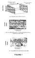
- the size of the datacube will be written in the form AxPxL, where A is the number of bands, P is the number of pixels in the cross-track and L is the number of lines in the along-track as depicted in Figure 1 .
- 204x120x128 is the size of a datacube that consists of 204 spectral bands, 128 lines in the along-track direction and 120 pixels in the cross-track direction.
- the test data set consists of two datacubes extracted from hyperspectral datacubes of two different sites; a vegetation-dominated site and a geological site.
- the first datacube is acquired using an Airborne Visible/Infra-Red Imagining Spectrometer (AVIRIS) [14] in the Greater Victoria Watershed District (GVWD), Canada, on August 12, 2002.
- the ground sample distance (GSD) of the datacube is 4m x 4m with nominal AVIRIS SNR of 1000:1.
- the term nominal SNR refers to the ratio of the signal to the noise in the Visible and Near InfraRed (VNIR) region in a given SNR pattern at certain circumstances [17].
- the datacube was processed to at-sensor radiance and 16-bit encoded.
- a 28m x 28m GSD datacube was derived by spatially averaging the 4m x 4m GSD datacube elevating the nominal SNR to 7000:1. Having such high SNR, this datacube is viewed as a pure datacube, i.e. a noise-free datacube [18], and is used as a reference to measure the SNR before and after denoising.
- the corresponding noisy datacube is developed by MacDonald Dettwiller Associates (MDA) Inc. according to a 600:1 SNR pattern in [17].
- the size of the datacube we extracted for testing is 202x120x128.
- the second test datacube is of size 210x128x128, extracted from a simulated datacube for Cuprite, Nevada, USA, with a nominal SNR of 600:1 obtained from the same source.
- the nominal SNR of 600:1 is chosen based on the recommendation of the user and science team of the Hyperspectral Environment and Resource Observer (HERO); a future Canadian hyperspectral satellite[19]. It is believed that a nominal SNR of 600:1 is a reasonable choice from the feasible range of the new instrument. This SNR value is a conclusion of comprehensive discussions and a delicate compromise that involves users requirements and several design parameters, e.g. data quality, cost, weight and technology availability.
- An objective of this invention is to improve the data quality of hyperspectral imagery through increasing their SNR by noise reduction.
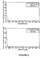
- the average power of the signal at a given pixel is concentrated at the low frequencies of the Fourier spectrum whereas the noise at a given pixel is white, i.e. uniformly distributed as shown in Figure 2 .
- This is similar to the noise environment that is normally targeted in the image denoising literature, yet there are two important differences in the noise environment that are targeted:
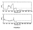
- Fig 4 shows the noise level of band images in terms of RMSE of the test datacubes.
- the top image relates to the GVWD datacube while the bottom image relates to the Cuprite datacube.
- the dashed lines are the average RMSE.
- the noise level is varying with signal level, based on sensor characteristics.
- the signal properties in the spectral dimension are not the same as that in the spatial dimensions due to the difference in their physical nature.
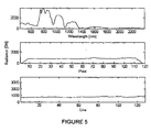
- a simple observation of a datacube reveals that the degree of regularity is higher in the spatial dimensions than in the spectral dimension. This can also be concluded by comparing the average radiance across the spectral band axis, on one hand, against the average radiance across the pixel axis and the line axis on the other hand as depicted in Figure 5 and Figure 6 .
- Fig 5 shows the average radiance of the GVWD datacube across the band axis (top image), across the pixel axis (middle image) and across the line axis (bottom image).
- Fig 6 shows the average radiance of the Cuprite datacube across the band axis (top image), across the pixel axis (middle image) and across the line axis (bottom image).
- the signal in the spatial domain can be seen as normal "real-life images" that carry considerable degree of regularity
- the signal in the spectral domain shows a number of local sharp features. For example, it contains absorption peaks due to atmosphere contents, red-edge due to chlorophyll contents, and other narrow absorption peaks due to cell structure and mineral absorption properties.
- Elevating noise level is achieved by transforming hyperspectral datacube into the spectral derivative domain, which is equivalent to highpass filtering. This leads to an increase in the noise-to-signal ratio because the signal power is concentrated in the low frequency region as shown in Figure 2 , whereas the noise is spread all over the Fourier spectrum.
- ⁇ is a spectral band center
- p is a cross-track pixel number
- l is an along-track line number
- ⁇ ⁇ is a small displacement in the spectral dimension.
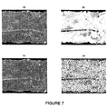
- Figures 7a-7d shows images at wavelength 470.93 nm from the pure GVWD datacube and the noisy datacube, as well as their corresponding spectral derivative images.
- Fig 7a shows the pure spectral band image of the GVWD datacube and
- Fig 7b shows the spectral derivate of the pure band image.
- Fig 7c shows the noisy spectral band image while
- Fig 7d shows the spectral derivative of the noisy band image.
- the average noise level is so low that it is not visible in the noisy signal in Figure 7c , the noise is clearly manifested in the derivative domain in Figure 7d .
- ⁇ , ⁇ and ⁇ are the spectral derivative of the noisy datacube, the spatially denoised derivative of the noisy datacube and the spatially-spectrally denoised derivative of the noisy datacube, respectively
- DWT2 is the 2-Dimensional (2-D) discrete wavelet transform applied to the along-track and across-track dimensions
- IDWT2 is the associated 2-D inverse discrete wavelet transform
- DWT is the 1-D discrete wavelet transform applied to the spectral dimension
- IDWT is the 1-D inverse discrete wavelet transform
- ⁇ spatial is a threshold function that is applied on band-by-band
- the mean-square error accumulated due to integration is growing with A, the total number of spectral bands.
- hyperspectral datacubes contain a large number of spectral bands, e.g. 205, which may result in accumulating an error (throughout the integration process) that is significantly larger than the initial noise.
- the noise level is initially low, from the problem definition. This means that the error accumulated in the integration process may not only reduce the denoising performance, but may also result in degradation of the signal quality if no action is taken.
- the cutoff frequency of the LPF is inversely proportional to the width of the correction window, meaning that a narrower window will replace a larger band of frequency components.
- the bandwidth of the filter is chosen to pass at least 98% of the signal power, which is at a Fourier normalized frequency that is slightly less than 0.1 as shown in Figure 2 . This is corresponding to a window width that is equal to 5 spectral bands.
- the denoised data may be evaluated next to the signal data as follows:
- a data set acquired by a satellite sensor has a considerable high level SNR.
- the level of noise might be considerable low.
- This technique is suitable for WS denoising because of its nonlinear nature.
- Elevating noise level is achieved by transforming hyperspectral datacube into the spectral derivative domain, which is equivalent to highpass filtering. This leads to an increase in the noise-to-signal ratio because the signal power is concentrated in the low frequency region, whereas the noise is spread all over the Fourier spectrum.
- ⁇ is a spectral band center
- p is a cross-track pixel number
- l is an along-track line number of a noisy datacube y ( ⁇ ,p,l )
- ⁇ I,2,..., N h
- p I,2,..., N c
- l I,2,..., N
- ⁇ ⁇ is a small displacement in the spectral dimension.
- N b , N c , N r are the total number of bands, total number of pixels per line and total number of cross-track lines of the datacube.
- DWT2 is the 2-D discrete wavelet transform applied to the spectral derivative of the band images (two spatial dimensions, i.e. along-track and across-track dimensions).
- IDWT2 is the associated 2-D inverse discrete wavelet transform.
- ⁇ spatial is a threshold function that is applied on band-by-band basis.
- DWT is the 1-D discrete wavelet transform applied to the spectra (i.e. spectral domain)
- IDWT is the associated 1-D inverse discrete wavelet transform
- ⁇ spectral is a threshold function that is applied to the spectra on pixel-by-pixel basis.
- the WS denoising is performed in derivative domain.
- the denoised derivatives need to be converted to the original spatial and spectral domains.
- the accumulation error after integration can be significantly larger than the initial noise (recall that the noise level is initially low from the problem definition). This means that the error accumulated in the integration process may not only reduce the denoising performance and cause instability, but may also result in degradation of the signal quality if no action is taken.
- the integration error is corrected by cancelling the accumulated error and compensating the cancelled signal using two identical low-pass filters as shown in the block diagram of the method and system. Moving average (MA) filters are used.
- the MA filter is applied using a sliding window of width ⁇ +1, which we refer to as the correction window.
- the cutoff frequency of the low-pass filter is inversely proportional to the width of the correction window.
- a narrower window will replace a larger band of frequency components.
- the bandwidth of the filter is chosen to pass at least 98% of the signal power, which is at a Fourier normalized frequency that is slightly less than 0.1. This is corresponding to a window width that is equal to 5 spectral bands.
- the proposed method was applied to the test datacubes and the results of this exercise are detailed in the below.
- the reason more than one datacube are considered, is to examine the proposed method for two major application types, namely vegetation and mineral applications.
- the GVWD datacube is an example of vegetation-dominated scene whereas the Cuprite datacube represents a scene that is rich in minerals.
- Table 1 and Table 3 list the SNR denoised after denoising the GVWD and the Cuprite datacubes, respectively, as well as the initial SNR before denoising of the noisy datacubes.
- Two types of wavelet families are implemented, namely Daubechies(N) and Coiflets(N) wavelets, where N is the order of the wavelet function. They both have N wavelet vanishing moments, however, Daubechies have more compact support whereas Coiflets have 2N-1 scaling function vanishing moments[21].
- the experiment is limited to one level of wavelet decomposition in order to allow for higher order wavelets to be examined.
- Three WS threshold methods are used, namely BayesShrink, SURE and Minimax.
- Table 1 below shows that the initial SNR of the noisy GVWD datacube is 2144.14 and the SNR after baseline WS denoising is up to 2335.71.
- the undecimated WS denoising and the 3-D WS denoising provide SNR up to 2453.57 and 2695.36, respectively. These results are consistent with the conclusions in [7]and [21]regarding the undecimated WS denoising and the 3-D WS denoising being better than the baseline WS, respectively.
- the Inter-Band Correlation (IBC) WS and the Besov Ball Projections (BBP) WS provide SNR of 2304.7 and 570.39, respectively.
- the proposed method provides an SNR up to 3954.85, which constitutes an improvement of 84.44%. If the two components of the proposed method, i.e. the hybrid spatial-spectral (HSS) component and the Spectral Derivative (SD) component, are applied separately, they provide improvements of up to 56.99% and 5.77%, respectively, as shown in Table 2. Yet, when they are combined, they achieve an SNR improvement (84.44%) that is significantly higher than the sum of the individual SNR improvements of the two components.
- HSS spatial-spectral
- SD Spectral Derivative
- the detailed per-band performance of the proposed method is plotted in Figure 9 , along with the performance of the other methods.
- the proposed HSSNR method shows SNR-per-band that is significantly higher than the other methods for most of the bands.
- Figure 9 shows the signal-to-noise ratio per band after noise reduction using Baseline WS, 3-D WS, Undecimated WS, the proposed Hybrid Spatial-Spectral derivative domain Noise Reduction (HSSNR) method, the Inter-Band Correlation (IBC) WS and the Besov Ball Projections (BBP) WS when applied to an AVIRIS Greater Victoria Watershed District (GVWD) datacube.
- HSSNR Hybrid Spatial-Spectral derivative domain Noise Reduction
- IBC Inter-Band Correlation
- BBP Besov Ball Projections
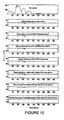
- Figure 10 shows a spectrum of an arbitrary pixel from the pure GVWD datacube, the difference between the pure spectrum, on one hand, and, on the other hand the spectra of the same pixel before and after being denoised by: the baseline WS, the undecimated WS, the 3-D WS, the proposed HSSNR method, the inter-band correlation WS and the Besov ball projections WS.
- the 3-D WS, the inter-band correlation WS and the Besov ball projections WS perform well in the range 1800nm to 2400nm but on average, the difference spectrum of the proposed HSSNR WS is the smallest. It outperforms the other methods in the range 800nm to 1200nm where most of the error is located.
- Table 3 shows that the proposed HSSNR method improves the datacube SNR from an initial value of 3961.45 to up to 7857.42, i.e. 98.35% improvement in SNR, which is significantly higher than the other methods.
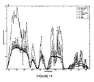
- FIG 11 shows that the Cuprite datacube SNR-per-band after being denoised by the proposed method is higher than the other methods especially in the VNIR region. Similar to the results obtained from the GVWD datacube, the detailed results from the Cuprite datacube in Table 4 show that the most contribution in the proposed HSSNR method is due to the HSS component.
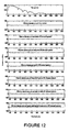
- Figure 12 shows a spectrum of an arbitrary pixel from the pure Cuprite datacube, the difference between the pure spectrum, on one hand, and, on the other hand, the spectra of the same pixel before and after being denoised by the various methods.
- the difference spectrum of the proposed HSSNR WS is smaller than the difference spectra of the other methods, while the Besov ball projection WS is the second best, e.g. compare the difference spectra around 800 nm, 1000 nm and 1100 nm.
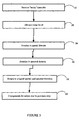
- the proposed method may be seen as a distinct series of steps to be executed. Such a series of steps may be diagrammed as a flowchart as show in Figure 3 .
- the method begins in step 10, that of receiving the "noisy" datacube.
- Step 20 then elevates the noise level in the data/signal. This can be done by transforming the hyperspectral datacube into the spectral derivative domain.
- Step 30 is that of denoising the image in the spatial domain. This can be done by, in turn, computing the 2D wavelet transform for each spectral band image of the spectral derivative of the noisy datacube, estimating a threshold value for each spectral band image, performing a soft threshold WS operation, and then computing an inverse 2-D wavelet transform.
- Step 40 then denoises the image in the spectral domain. This is ideally done on the spatially denoised datacube but it can be done after step 20.
- the denoising in the spectral domain is similar to step 30. It may be done by : computing the 1 D wavelet transform for the spectrum of each spatial pixel at a specific location of the datacube, estimating a threshold value for each spectrum, performing a soft threshold WS operation, and then computing an inverse 1-D wavelet transform.
- the signal is then retrieved to result in the original spatial and spectral domains by integration (step 50).
- integration may introduce errors into the data, these errors are corrected for in step 60.
- Such correction may take the form of compensating the cancelled signal using low pass filters which use a moving average or a sliding/correction window.
- SNR signal-to-noise ratio
- the invention may also take the form of a system that executes the steps in the method. Such a system is illustrated in Figure 8 .
- the system receives the noisy datacube y ( ⁇ , p,l ) at the leftmost side of the diagram.
- a spectral derivative block takes the spectral derivative of the datacube and converts the datacube into its spectral derivative ⁇ ( ⁇ ).
- a spatial denoising block then executes spatial denoising on ⁇ ( ⁇ ) to result in ⁇ ( ⁇ ), the spatially denoised result.
- a spectral denoising block then executes spectral denoising on ⁇ ( ⁇ ) to result in ⁇ ( p,l ), the spectrally denoised result at point (p,l).
- the resulting ⁇ ( p,l ) is then integrated by an integration block to result in x ⁇ ( ⁇ , p,l ), the denoised signal.
- Two identical moving average filters (basically low pass filters) then correct x ⁇ ( ⁇ , p,l ) one filter filters x ⁇ ( ⁇ , p,l ) and subtracts the result from x ⁇ ( ⁇ , p,l ).
- Another filter filters the original data y ( ⁇ , p,l ) and adds the result to x ⁇ ( ⁇ , p,l ) . This results in the final denoised datacube x ⁇ ( ⁇ , p,l ).
- Embodiments of the invention may be implemented in any conventional computer programming language.
- preferred embodiments may be implemented in a procedural programming language (e.g. "C") or an object oriented language (e.g. "C++").
- Alternative embodiments of the invention may be implemented as pre-programmed hardware elements, other related components, or as a combination of hardware and software components.
- Embodiments can be implemented as a computer program product for use with a computer system.
- Such implementation may include a series of computer instructions fixed either on a tangible medium, such as a computer readable medium (e.g ., a diskette, CD-ROM, ROM, or fixed disk) or transmittable to a computer system, via a modem or other interface device, such as a communications adapter connected to a network over a medium.
- the medium may be either a tangible medium (e.g ., optical or electrical communications lines) or a medium implemented with wireless techniques (e.g ., microwave, infrared or other transmission techniques).
- the series of computer instructions embodies all or part of the functionality previously described herein.
- Such computer instructions can be written in a number of programming languages for use with many computer architectures or operating systems. Furthermore, such instructions may be stored in any memory device, such as semiconductor, magnetic, optical or other memory devices, and may be transmitted using any communications technology, such as optical, infrared, microwave, or other transmission technologies. It is expected that such a computer program product may be distributed as a removable medium with accompanying printed or electronic documentation (e.g ., shrink wrapped software), preloaded with a computer system ( e.g ., on system ROM or fixed disk), or distributed from a server over the network (e.g ., the Internet or World Wide Web).
- a removable medium with accompanying printed or electronic documentation (e.g ., shrink wrapped software), preloaded with a computer system (e.g ., on system ROM or fixed disk), or distributed from a server over the network (e.g ., the Internet or World Wide Web).
- embodiments of the invention may be implemented as a combination of both software (e.g ., a computer program product) and hardware. Still other embodiments of the invention may be implemented as entirely hardware, or entirely software (e.g ., a computer program product).
Landscapes
- Physics & Mathematics (AREA)
- General Physics & Mathematics (AREA)
- Engineering & Computer Science (AREA)
- Theoretical Computer Science (AREA)
- Image Processing (AREA)
- Stereo-Broadcasting Methods (AREA)
- Interface Circuits In Exchanges (AREA)
- Reduction Or Emphasis Of Bandwidth Of Signals (AREA)
Claims (13)
- Procédé pour améliorer un rapport signal sur bruit des données dans un cube de données multidimensionnelles, lesdites données étant dans un domaine d'origine ayant deux dimensions spatiales et une dimension spectrale, ledit procédé étant caractérisé para) l'élévation d'un niveau de bruit desdites données en transformant ledit cube de données dans un domaine de dérivé spatial pour aboutir à des données transforméesb) l'enlèvement du bruit desdites données transformées dans un domaine spatial en utilisant une transformée en ondelettes bidimensionnellec) l'enlèvement du bruit desdites données transformées dans un domaine spectral en utilisant une transformée en ondelettes unidimensionnelled) la conversion des données débruitées dans ledit domaine d'origine par intégration spectralee) la correction des erreurs introduites dans lesdites données par l'étape d)
- Procédé selon la revendication 1, dans lequel l'étape a) est accomplie en utilisant une formule

oùλ représente un centre de la bande spectrale,p représente un nombre de pixels dans le sens transversal,l représente un nombre de lignes dans le sens longitudinal dudit cube de donnéesy(λ, p,l) λ= i, 2,..., Nb_; p= 1,2,..., Nc , l=1,2,...Nr représente ledit cube de données dans ledit domaine d'origine etδλ est un petit déplacement dans la dimension spectraleNb représente un nombre total de bandesNr représente un nombre total de lignesNc représente un nombre de pixels par ligne. - Procédé selon la revendication 1, dans lequel l'étape b) est accomplie par une série d'étapes incluant le calcul d'une transformée en ondelettes bidimensionnelle pour chaque image de bande spectrale d'une dérivée spectrale dudit cube de données, ladite série d'étapes comprenant en outre :- l'estimation d'une valeur de seuil pour chaque image de bande spectrale- la réalisation d'une opération de rétrécissement d'ondelettes à seuil variable- le calcul d'une transformée en ondelettes bidimensionnelle inverse.
- Procédé selon la revendication 3, dans lequel ladite transformée en ondelettes bidimensionnelle inverse comprend :

dans laquelleθ(λ) représente une dérivée spectrale d'une image de bande à la bande λ dudit cube de donnéesθ̃(λ) représente une image de bande spectrale à dérivée spatialement débruitée dudit cube de donnéesDWT2 représente une transformée en ondelettes discrète bidimensionnelle appliquée à ladite dérivée spectrale desdites images de bande à deux dimensions spatiales (dimensions transversale et longitudinale)IDWT2 représente une transformée en ondelettes discrète inverse bidimensionnelle associéeη spatial est une fonction de seuil appliquée à ladite image de bande sur une base bande par bande pour ledit cube de données entier. - Procédé selon la revendication 1, dans lequel l'étape c) est accomplie par une série d'étapes incluant le calcul d'une transformée en ondelettes unidimensionnelle pour chaque spectre correspondant à un pixel spatial à chaque position au niveau du cube de données spatialement débruitées résultant de l'étape b).
- Procédé selon la revendication 5, dans lequel ladite série d'étapes comprend en outre :- l'estimation d'une valeur de seuil pour chaque image de bande spectrale- la réalisation d'une opération de rétécissement d'ondelettes à seuil variable- le calcul d'une transformée en ondelettes unidimensionnelle inverse.
- Procédé selon la revendication 6, dans lequel ladite transformée en ondelettes unidimensionnelle inverse comprend :

dans laquelleθ̃(p,l) est une dérivée du spectre d'un cube de données spatialement débruitées à une position spatiale (p,l)θ̃(p,l) est une dérivée du spectre spatialement et spectralement débruité dudit cube de données à une position (p,l)DWT est une transformée en ondelettes discrète unidimensionnelle appliquée à un spectreIDWT est une transformée en ondelettes discrète unidimensionnelle inverse associéeη spectral est une fonction de seuil appliquée audit spectre sur une base pixel par pixel pour ledit cube de données entier. - Procédé selon la revendication 1, dans lequel l'étape d) est accomplie en utilisant une formule :

dans laquelleλ i est une longueur d'onde centrale d'une i ème bande spectraleλ j est une longueur d'onde centrale d'une jème bande spectralex1(ρ,l) est un signal débruité d'un pixel à une position (ρ,l) dans la première bande spectraley(λ1,ρ,l) est un signal bruyant d'un pixel à une position (ρ,l) dans la première bande spectrale etx̂l(p,l) = y(λ l,p,l) représente ledit cube de données dans ledit domaine d'origine. - Procédé selon la revendication 8, dans lequel l'étape e) est accomplie en annulant une erreur accumulée par l'étape d) en compensant un signal annulé.
- Procédé selon la revendication 9, dans lequel ladite compensation dudit signal annulé est accomplie par filtrage.
- Procédé selon la revendication 10, dans lequel au moins deux filtres passe-bas identiques sont utilisés pour compenser ledit signal annulé.
- Procédé selon la revendication 11, dans lequel lesdits filtres remplacent les composantes de fréquence passe-bas d'un signal débruité de l'étape d) par des composantes de fréquence basse d'un signal d'origine obtenu à partir dudit cube de données de sorte que

Δ+1 est une largeur d'une fenêtre de correction utilisée par lesdits filtresx̂(λ,p,l) est un signal débruité avant correctionx̃(λ,p,l) est un signal débruité après correctiony(λ,ρ,l) est un signal bruyant. - Système pour augmenter un rapport signal sur bruit de données multidimensionnelles, lesdites données étant dans un domaine d'origine, le système comprenant :- un moyen pour élever les niveaux de bruit desdites données en transformant ledit cube de données en un domaine de dérivée spatiale pour aboutir à des données transformées ;- un moyen pour enlever le bruit desdites données transformées dans un domaine spatial en utilisant une transformée en ondelettes bidimensionnelle ;- un moyen pour enlever le bruit desdites données transformées dans un domaine spectral en utilisant une transformée en ondelettes unidimensionnelle pour donner des donnés débruitées ;- un moyen pour convertir les données débruitées dans ledit domaine d'origine par intégration spectrale ;- un moyen pour corriger les erreurs introduites dans lesdites données par une conversion desdites données débruitées.
Applications Claiming Priority (2)
| Application Number | Priority Date | Filing Date | Title |
|---|---|---|---|
| US76338106P | 2006-01-31 | 2006-01-31 | |
| PCT/CA2007/000114 WO2007087702A1 (fr) | 2006-01-31 | 2007-01-29 | Procédé et système permettant d'augmenter le rapport signal sur bruit |
Publications (3)
| Publication Number | Publication Date |
|---|---|
| EP1982305A1 EP1982305A1 (fr) | 2008-10-22 |
| EP1982305A4 EP1982305A4 (fr) | 2010-04-28 |
| EP1982305B1 true EP1982305B1 (fr) | 2011-06-15 |
Family
ID=38327099
Family Applications (1)
| Application Number | Title | Priority Date | Filing Date |
|---|---|---|---|
| EP07719355A Not-in-force EP1982305B1 (fr) | 2006-01-31 | 2007-01-29 | Procede et systeme permettant d'augmenter le rapport signal sur bruit |
Country Status (5)
| Country | Link |
|---|---|
| US (1) | US8358866B2 (fr) |
| EP (1) | EP1982305B1 (fr) |
| AT (1) | ATE513277T1 (fr) |
| CA (1) | CA2640683C (fr) |
| WO (1) | WO2007087702A1 (fr) |
Families Citing this family (29)
| Publication number | Priority date | Publication date | Assignee | Title |
|---|---|---|---|---|
| EP1982305B1 (fr) | 2006-01-31 | 2011-06-15 | Canadian Space Agency | Procede et systeme permettant d'augmenter le rapport signal sur bruit |
| US8992446B2 (en) * | 2009-06-21 | 2015-03-31 | Holland Bloorview Kids Rehabilitation Hospital | Procedure for denoising dual-axis swallowing accelerometry signals |
| US8542410B2 (en) * | 2009-09-08 | 2013-09-24 | Xerox Corporation | Least squares based exposure modulation for banding compensation |
| EP2732431B1 (fr) * | 2011-07-15 | 2019-03-13 | Koninklijke Philips N.V. | Tomodensitométrie spectrale |
| WO2014080961A1 (fr) * | 2012-11-20 | 2014-05-30 | 株式会社 東芝 | Dispositif de traitement d'image, procédé de traitement d'image et dispositif de diagnostic à rayons x |
| JP6205742B2 (ja) * | 2013-02-13 | 2017-10-04 | 株式会社リコー | 画像処理装置、画像処理方法、及び画像処理プログラム |
| JP2016038614A (ja) * | 2014-08-05 | 2016-03-22 | 株式会社リコー | 機器、情報処理システム、情報処理方法、及び情報処理プログラム |
| WO2016100797A1 (fr) | 2014-12-18 | 2016-06-23 | Conocophillips Company | Procédés de séparation de source simultanée |
| EP3091503A1 (fr) * | 2015-05-05 | 2016-11-09 | BAE Systems PLC | Traitement de signal |
| US9569843B1 (en) * | 2015-09-09 | 2017-02-14 | Siemens Healthcare Gmbh | Parameter-free denoising of complex MR images by iterative multi-wavelet thresholding |
| WO2017058723A1 (fr) | 2015-09-28 | 2017-04-06 | Conocophillips Company | Acquisition sismique en 3d |
| KR101737426B1 (ko) * | 2016-02-04 | 2017-05-18 | 한국해양과학기술원 | 최소 잡음 비율 변환기법을 이용한 위성 또는 항공기에서 촬영된 영상의 인위적인 잡음신호 보정 방법 |
| US10809402B2 (en) | 2017-05-16 | 2020-10-20 | Conocophillips Company | Non-uniform optimal survey design principles |
| US10643309B2 (en) | 2017-11-09 | 2020-05-05 | Spectral Sciences, Inc. | Signal-to-noise enhancement |
| AU2018368796B2 (en) | 2017-11-20 | 2023-10-12 | Shearwater Geoservices Software Inc. | Offshore application of non-uniform optimal sampling survey design |
| US10970879B2 (en) | 2018-04-26 | 2021-04-06 | Ppg Industries Ohio, Inc. | Formulation systems and methods employing target coating data results |
| US11119035B2 (en) | 2018-04-26 | 2021-09-14 | Ppg Industries Ohio, Inc. | Systems and methods for rapid coating composition determinations |
| US11874220B2 (en) | 2018-04-26 | 2024-01-16 | Ppg Industries Ohio, Inc. | Formulation systems and methods employing target coating data results |
| US10871888B2 (en) * | 2018-04-26 | 2020-12-22 | Ppg Industries Ohio, Inc. | Systems, methods, and interfaces for rapid coating generation |
| WO2020069143A1 (fr) * | 2018-09-30 | 2020-04-02 | Conocophillips Company | Récupération de signal fondée sur un apprentissage automatique |
| CN110298414B (zh) * | 2019-07-09 | 2022-12-06 | 西安电子科技大学 | 基于去噪组合降维和引导滤波的高光谱图像分类方法 |
| CN111175335B (zh) * | 2020-01-17 | 2023-05-02 | 武汉中科牛津波谱技术有限公司 | 一种核磁共振t1噪声的压制方法 |
| CN112818794B (zh) * | 2021-01-25 | 2022-03-04 | 哈尔滨工业大学 | 基于递进式空谱联合深度网络的高光谱遥感图像生成方法 |
| CN112950500B (zh) * | 2021-02-25 | 2022-08-26 | 桂林电子科技大学 | 一种基于边缘检测低秩全变分模型的高光谱去噪方法 |
| CN113910005B (zh) * | 2021-09-10 | 2023-03-14 | 中国医学科学院北京协和医院 | 磨削系统的信号处理方法、装置及磨削系统 |
| CN114488197A (zh) * | 2021-12-28 | 2022-05-13 | 浙江大学嘉兴研究院 | 一种双视场高光谱分辨率激光雷达数据质量自动判别的方法 |
| CN114519373B (zh) * | 2022-02-10 | 2024-05-10 | 中国科学院上海技术物理研究所 | 一种采用红外长波焦平面探测器的干涉信号去噪方法 |
| CN117725362B (zh) * | 2023-12-11 | 2026-06-23 | 海南大学 | 一种基于小波分析的气液两相流流型识别方法 |
| CN119249074B (zh) * | 2024-12-04 | 2025-05-02 | 河海大学 | 星载光子计数激光雷达点云去噪方法、装置及存储介质 |
Family Cites Families (12)
| Publication number | Priority date | Publication date | Assignee | Title |
|---|---|---|---|---|
| US6892089B1 (en) * | 1999-04-22 | 2005-05-10 | Johns Hopkins University | Cardiac motion tracking using cine harmonic phase (HARP) magnetic resonance imaging |
| US6741739B1 (en) * | 2000-05-03 | 2004-05-25 | Itt Manufacturing Enterprises | Method and apparatus for improving signal to noise ratio using wavelet decomposition and frequency thresholding |
| US6633683B1 (en) * | 2000-06-26 | 2003-10-14 | Miranda Technologies Inc. | Apparatus and method for adaptively reducing noise in a noisy input image signal |
| FR2820227B1 (fr) * | 2001-01-30 | 2003-04-18 | France Telecom | Procede et dispositif de reduction de bruit |
| US7876820B2 (en) * | 2001-09-04 | 2011-01-25 | Imec | Method and system for subband encoding and decoding of an overcomplete representation of the data structure |
| US6819790B2 (en) * | 2002-04-12 | 2004-11-16 | The University Of Chicago | Massive training artificial neural network (MTANN) for detecting abnormalities in medical images |
| JP3838163B2 (ja) * | 2002-06-13 | 2006-10-25 | 松下電器産業株式会社 | ノイズ低減装置 |
| FR2854245B1 (fr) * | 2003-04-28 | 2005-12-23 | Geophysique Cie Gle | Procede de traitement de cubes sismiques correspondant a des acquisitions realisees pour une meme zone a des moments differents |
| US7260272B2 (en) * | 2003-07-10 | 2007-08-21 | Samsung Electronics Co.. Ltd. | Method and apparatus for noise reduction using discrete wavelet transform |
| KR100624421B1 (ko) * | 2004-05-04 | 2006-09-19 | 삼성전자주식회사 | 디지탈 영상 신호 필터링 장치 및 방법 |
| EP1982305B1 (fr) | 2006-01-31 | 2011-06-15 | Canadian Space Agency | Procede et systeme permettant d'augmenter le rapport signal sur bruit |
| US8149336B2 (en) * | 2008-05-07 | 2012-04-03 | Honeywell International Inc. | Method for digital noise reduction in low light video |
-
2007
- 2007-01-29 EP EP07719355A patent/EP1982305B1/fr not_active Not-in-force
- 2007-01-29 CA CA2640683A patent/CA2640683C/fr not_active Expired - Fee Related
- 2007-01-29 AT AT07719355T patent/ATE513277T1/de not_active IP Right Cessation
- 2007-01-29 US US12/223,283 patent/US8358866B2/en not_active Expired - Fee Related
- 2007-01-29 WO PCT/CA2007/000114 patent/WO2007087702A1/fr not_active Ceased
Also Published As
| Publication number | Publication date |
|---|---|
| US8358866B2 (en) | 2013-01-22 |
| CA2640683A1 (fr) | 2007-08-09 |
| ATE513277T1 (de) | 2011-07-15 |
| EP1982305A4 (fr) | 2010-04-28 |
| EP1982305A1 (fr) | 2008-10-22 |
| US20110170796A1 (en) | 2011-07-14 |
| CA2640683C (fr) | 2014-10-21 |
| WO2007087702A1 (fr) | 2007-08-09 |
Similar Documents
| Publication | Publication Date | Title |
|---|---|---|
| US8358866B2 (en) | Method and system for increasing signal-to-noise ratio | |
| Pradhan et al. | Estimation of the number of decomposition levels for a wavelet-based multiresolution multisensor image fusion | |
| Hou et al. | SAR image despeckling based on nonsubsampled shearlet transform | |
| EP3229038A1 (fr) | Procédé de filtrage de phase interférométrique insar de domaine d'ondelette | |
| CN103077508B (zh) | 基于变换域非局部和最小均方误差的sar图像去噪方法 | |
| Ilesanmi et al. | Multiscale hybrid algorithm for pre-processing of ultrasound images | |
| Jing et al. | SAR image de-noising via grouping-based PCA and guided filter | |
| Hallabia et al. | High spectral quality pansharpening approach based on MTF-matched filter banks | |
| CN118759487B (zh) | 一种sar脉冲式射频干扰抑制方法 | |
| Wang et al. | Adaptively weighted nonlocal means and TV minimization for speckle reduction in SAR images | |
| Pande-Chhetri et al. | Filtering high-resolution hyperspectral imagery in a maximum noise fraction transform domain using wavelet-based de-striping | |
| Mastriani et al. | Smoothing of coefficients in wavelet domain for speckle reduction in Synthetic Aperture Radar images | |
| Simon | A novel statistical fusion rule for image fusion and its comparison in non subsampled contourlet transform domain and wavelet domain | |
| Abdikan et al. | Comparison of different fusion algorithms in urban and agricultural areas using SAR (PALSAR and RADARSAT) and optical (SPOT) images | |
| Lu et al. | SAR image despeckling via structural sparse representation | |
| Wu et al. | Remote sensing image noise reduction using wavelet coefficients based on OMP | |
| Anand et al. | Multispectral image denoising with a new noise estimation algorithm | |
| Hadj-Rabah et al. | Impact of contextual filtering on tomosar detection | |
| Sheela et al. | Comparative analysis of various filtering techniques for Speckle noise suppression in Ultrasound images | |
| Gore Biday et al. | Relative radiometric correction of multitemporal satellite imagery using Fourier and wavelet transform | |
| Micheal et al. | Multi-sensor image fusion of the lunar image data using DT-CWT and curvelet transform | |
| Hakim et al. | An adaptive stripe noise removal algorithm for optical satellite imagery | |
| Ray et al. | Towards deriving an optimal approach for denoising of risat-1 sar data using wavelet transform | |
| Sivapriya et al. | Iterative dual tree wavelet transform with posterior probability for sar despeckling | |
| Farhadiani et al. | Evaluation of polarimetric sar despeckling methods for crop classification from rcm compact polarimetry data |
Legal Events
| Date | Code | Title | Description |
|---|---|---|---|
| PUAI | Public reference made under article 153(3) epc to a published international application that has entered the european phase |
Free format text: ORIGINAL CODE: 0009012 |
|
| 17P | Request for examination filed |
Effective date: 20080819 |
|
| AK | Designated contracting states |
Kind code of ref document: A1 Designated state(s): AT BE BG CH CY CZ DE DK EE ES FI FR GB GR HU IE IS IT LI LT LU LV MC NL PL PT RO SE SI SK TR |
|
| A4 | Supplementary search report drawn up and despatched |
Effective date: 20100331 |
|
| RIC1 | Information provided on ipc code assigned before grant |
Ipc: G06T 5/10 20060101ALI20100323BHEP Ipc: G06F 17/10 20060101ALI20100323BHEP Ipc: G06T 5/00 20060101AFI20070911BHEP |
|
| 17Q | First examination report despatched |
Effective date: 20100702 |
|
| GRAP | Despatch of communication of intention to grant a patent |
Free format text: ORIGINAL CODE: EPIDOSNIGR1 |
|
| RIC1 | Information provided on ipc code assigned before grant |
Ipc: G06T 5/10 20060101ALI20101108BHEP Ipc: G06F 17/10 20060101ALI20101108BHEP Ipc: G06T 5/00 20060101AFI20101108BHEP |
|
| GRAS | Grant fee paid |
Free format text: ORIGINAL CODE: EPIDOSNIGR3 |
|
| GRAA | (expected) grant |
Free format text: ORIGINAL CODE: 0009210 |
|
| AK | Designated contracting states |
Kind code of ref document: B1 Designated state(s): AT BE BG CH CY CZ DE DK EE ES FI FR GB GR HU IE IS IT LI LT LU LV MC NL PL PT RO SE SI SK TR |
|
| REG | Reference to a national code |
Ref country code: GB Ref legal event code: FG4D Ref country code: CH Ref legal event code: EP |
|
| REG | Reference to a national code |
Ref country code: IE Ref legal event code: FG4D |
|
| REG | Reference to a national code |
Ref country code: DE Ref legal event code: R096 Ref document number: 602007015227 Country of ref document: DE Effective date: 20110721 |
|
| REG | Reference to a national code |
Ref country code: NL Ref legal event code: VDEP Effective date: 20110615 |
|
| PG25 | Lapsed in a contracting state [announced via postgrant information from national office to epo] |
Ref country code: SE Free format text: LAPSE BECAUSE OF FAILURE TO SUBMIT A TRANSLATION OF THE DESCRIPTION OR TO PAY THE FEE WITHIN THE PRESCRIBED TIME-LIMIT Effective date: 20110615 Ref country code: LT Free format text: LAPSE BECAUSE OF FAILURE TO SUBMIT A TRANSLATION OF THE DESCRIPTION OR TO PAY THE FEE WITHIN THE PRESCRIBED TIME-LIMIT Effective date: 20110615 |
|
| PG25 | Lapsed in a contracting state [announced via postgrant information from national office to epo] |
Ref country code: SI Free format text: LAPSE BECAUSE OF FAILURE TO SUBMIT A TRANSLATION OF THE DESCRIPTION OR TO PAY THE FEE WITHIN THE PRESCRIBED TIME-LIMIT Effective date: 20110615 Ref country code: AT Free format text: LAPSE BECAUSE OF FAILURE TO SUBMIT A TRANSLATION OF THE DESCRIPTION OR TO PAY THE FEE WITHIN THE PRESCRIBED TIME-LIMIT Effective date: 20110615 Ref country code: GR Free format text: LAPSE BECAUSE OF FAILURE TO SUBMIT A TRANSLATION OF THE DESCRIPTION OR TO PAY THE FEE WITHIN THE PRESCRIBED TIME-LIMIT Effective date: 20110916 Ref country code: LV Free format text: LAPSE BECAUSE OF FAILURE TO SUBMIT A TRANSLATION OF THE DESCRIPTION OR TO PAY THE FEE WITHIN THE PRESCRIBED TIME-LIMIT Effective date: 20110615 Ref country code: FI Free format text: LAPSE BECAUSE OF FAILURE TO SUBMIT A TRANSLATION OF THE DESCRIPTION OR TO PAY THE FEE WITHIN THE PRESCRIBED TIME-LIMIT Effective date: 20110615 Ref country code: CY Free format text: LAPSE BECAUSE OF FAILURE TO SUBMIT A TRANSLATION OF THE DESCRIPTION OR TO PAY THE FEE WITHIN THE PRESCRIBED TIME-LIMIT Effective date: 20110615 |
|
| PG25 | Lapsed in a contracting state [announced via postgrant information from national office to epo] |
Ref country code: BE Free format text: LAPSE BECAUSE OF FAILURE TO SUBMIT A TRANSLATION OF THE DESCRIPTION OR TO PAY THE FEE WITHIN THE PRESCRIBED TIME-LIMIT Effective date: 20110615 Ref country code: NL Free format text: LAPSE BECAUSE OF FAILURE TO SUBMIT A TRANSLATION OF THE DESCRIPTION OR TO PAY THE FEE WITHIN THE PRESCRIBED TIME-LIMIT Effective date: 20110615 |
|
| PG25 | Lapsed in a contracting state [announced via postgrant information from national office to epo] |
Ref country code: IS Free format text: LAPSE BECAUSE OF FAILURE TO SUBMIT A TRANSLATION OF THE DESCRIPTION OR TO PAY THE FEE WITHIN THE PRESCRIBED TIME-LIMIT Effective date: 20111015 Ref country code: EE Free format text: LAPSE BECAUSE OF FAILURE TO SUBMIT A TRANSLATION OF THE DESCRIPTION OR TO PAY THE FEE WITHIN THE PRESCRIBED TIME-LIMIT Effective date: 20110615 Ref country code: CZ Free format text: LAPSE BECAUSE OF FAILURE TO SUBMIT A TRANSLATION OF THE DESCRIPTION OR TO PAY THE FEE WITHIN THE PRESCRIBED TIME-LIMIT Effective date: 20110615 Ref country code: PT Free format text: LAPSE BECAUSE OF FAILURE TO SUBMIT A TRANSLATION OF THE DESCRIPTION OR TO PAY THE FEE WITHIN THE PRESCRIBED TIME-LIMIT Effective date: 20111017 |
|
| PG25 | Lapsed in a contracting state [announced via postgrant information from national office to epo] |
Ref country code: RO Free format text: LAPSE BECAUSE OF FAILURE TO SUBMIT A TRANSLATION OF THE DESCRIPTION OR TO PAY THE FEE WITHIN THE PRESCRIBED TIME-LIMIT Effective date: 20110615 Ref country code: SK Free format text: LAPSE BECAUSE OF FAILURE TO SUBMIT A TRANSLATION OF THE DESCRIPTION OR TO PAY THE FEE WITHIN THE PRESCRIBED TIME-LIMIT Effective date: 20110615 Ref country code: PL Free format text: LAPSE BECAUSE OF FAILURE TO SUBMIT A TRANSLATION OF THE DESCRIPTION OR TO PAY THE FEE WITHIN THE PRESCRIBED TIME-LIMIT Effective date: 20110615 |
|
| PLBE | No opposition filed within time limit |
Free format text: ORIGINAL CODE: 0009261 |
|
| STAA | Information on the status of an ep patent application or granted ep patent |
Free format text: STATUS: NO OPPOSITION FILED WITHIN TIME LIMIT |
|
| 26N | No opposition filed |
Effective date: 20120316 |
|
| PG25 | Lapsed in a contracting state [announced via postgrant information from national office to epo] |
Ref country code: DK Free format text: LAPSE BECAUSE OF FAILURE TO SUBMIT A TRANSLATION OF THE DESCRIPTION OR TO PAY THE FEE WITHIN THE PRESCRIBED TIME-LIMIT Effective date: 20110615 |
|
| REG | Reference to a national code |
Ref country code: DE Ref legal event code: R097 Ref document number: 602007015227 Country of ref document: DE Effective date: 20120316 |
|
| PG25 | Lapsed in a contracting state [announced via postgrant information from national office to epo] |
Ref country code: MC Free format text: LAPSE BECAUSE OF NON-PAYMENT OF DUE FEES Effective date: 20120131 |
|
| REG | Reference to a national code |
Ref country code: CH Ref legal event code: PL |
|
| GBPC | Gb: european patent ceased through non-payment of renewal fee |
Effective date: 20120129 |
|
| REG | Reference to a national code |
Ref country code: IE Ref legal event code: MM4A |
|
| PG25 | Lapsed in a contracting state [announced via postgrant information from national office to epo] |
Ref country code: GB Free format text: LAPSE BECAUSE OF NON-PAYMENT OF DUE FEES Effective date: 20120129 Ref country code: LI Free format text: LAPSE BECAUSE OF NON-PAYMENT OF DUE FEES Effective date: 20120131 Ref country code: CH Free format text: LAPSE BECAUSE OF NON-PAYMENT OF DUE FEES Effective date: 20120131 |
|
| PG25 | Lapsed in a contracting state [announced via postgrant information from national office to epo] |
Ref country code: IE Free format text: LAPSE BECAUSE OF NON-PAYMENT OF DUE FEES Effective date: 20120129 |
|
| PG25 | Lapsed in a contracting state [announced via postgrant information from national office to epo] |
Ref country code: ES Free format text: LAPSE BECAUSE OF FAILURE TO SUBMIT A TRANSLATION OF THE DESCRIPTION OR TO PAY THE FEE WITHIN THE PRESCRIBED TIME-LIMIT Effective date: 20110926 |
|
| PG25 | Lapsed in a contracting state [announced via postgrant information from national office to epo] |
Ref country code: BG Free format text: LAPSE BECAUSE OF FAILURE TO SUBMIT A TRANSLATION OF THE DESCRIPTION OR TO PAY THE FEE WITHIN THE PRESCRIBED TIME-LIMIT Effective date: 20110915 |
|
| PG25 | Lapsed in a contracting state [announced via postgrant information from national office to epo] |
Ref country code: TR Free format text: LAPSE BECAUSE OF FAILURE TO SUBMIT A TRANSLATION OF THE DESCRIPTION OR TO PAY THE FEE WITHIN THE PRESCRIBED TIME-LIMIT Effective date: 20110615 |
|
| PG25 | Lapsed in a contracting state [announced via postgrant information from national office to epo] |
Ref country code: LU Free format text: LAPSE BECAUSE OF NON-PAYMENT OF DUE FEES Effective date: 20120129 |
|
| PG25 | Lapsed in a contracting state [announced via postgrant information from national office to epo] |
Ref country code: HU Free format text: LAPSE BECAUSE OF FAILURE TO SUBMIT A TRANSLATION OF THE DESCRIPTION OR TO PAY THE FEE WITHIN THE PRESCRIBED TIME-LIMIT Effective date: 20070129 |
|
| REG | Reference to a national code |
Ref country code: FR Ref legal event code: PLFP Year of fee payment: 9 |
|
| PGFP | Annual fee paid to national office [announced via postgrant information from national office to epo] |
Ref country code: DE Payment date: 20150122 Year of fee payment: 9 Ref country code: IT Payment date: 20150128 Year of fee payment: 9 |
|
| PGFP | Annual fee paid to national office [announced via postgrant information from national office to epo] |
Ref country code: FR Payment date: 20150127 Year of fee payment: 9 |
|
| REG | Reference to a national code |
Ref country code: DE Ref legal event code: R082 Ref document number: 602007015227 Country of ref document: DE |
|
| REG | Reference to a national code |
Ref country code: DE Ref legal event code: R119 Ref document number: 602007015227 Country of ref document: DE |
|
| REG | Reference to a national code |
Ref country code: FR Ref legal event code: ST Effective date: 20160930 |
|
| PG25 | Lapsed in a contracting state [announced via postgrant information from national office to epo] |
Ref country code: DE Free format text: LAPSE BECAUSE OF NON-PAYMENT OF DUE FEES Effective date: 20160802 |
|
| PG25 | Lapsed in a contracting state [announced via postgrant information from national office to epo] |
Ref country code: FR Free format text: LAPSE BECAUSE OF NON-PAYMENT OF DUE FEES Effective date: 20160201 |
|
| PG25 | Lapsed in a contracting state [announced via postgrant information from national office to epo] |
Ref country code: IT Free format text: LAPSE BECAUSE OF NON-PAYMENT OF DUE FEES Effective date: 20160129 |