EP1982580A2 - Elément auxiliaire agricole - Google Patents
Elément auxiliaire agricole Download PDFInfo
- Publication number
- EP1982580A2 EP1982580A2 EP08003494A EP08003494A EP1982580A2 EP 1982580 A2 EP1982580 A2 EP 1982580A2 EP 08003494 A EP08003494 A EP 08003494A EP 08003494 A EP08003494 A EP 08003494A EP 1982580 A2 EP1982580 A2 EP 1982580A2
- Authority
- EP
- European Patent Office
- Prior art keywords
- attachment
- propeller shaft
- tractor
- shaft holder
- attachment according
- Prior art date
- Legal status (The legal status is an assumption and is not a legal conclusion. Google has not performed a legal analysis and makes no representation as to the accuracy of the status listed.)
- Withdrawn
Links
- 238000010168 coupling process Methods 0.000 claims abstract description 41
- 238000005859 coupling reaction Methods 0.000 claims abstract description 41
- 230000008878 coupling Effects 0.000 claims abstract description 40
- 230000002401 inhibitory effect Effects 0.000 claims description 34
- 238000006073 displacement reaction Methods 0.000 abstract 2
- 239000003112 inhibitor Substances 0.000 description 3
- 230000000903 blocking effect Effects 0.000 description 2
- 230000000295 complement effect Effects 0.000 description 2
- 241001236644 Lavinia Species 0.000 description 1
- 230000006978 adaptation Effects 0.000 description 1
- 230000005540 biological transmission Effects 0.000 description 1
- 239000002981 blocking agent Substances 0.000 description 1
- 230000001447 compensatory effect Effects 0.000 description 1
- 230000001419 dependent effect Effects 0.000 description 1
- 230000000694 effects Effects 0.000 description 1
- 230000036316 preload Effects 0.000 description 1
- 238000005086 pumping Methods 0.000 description 1
- 230000000452 restraining effect Effects 0.000 description 1
- 238000005096 rolling process Methods 0.000 description 1
- 238000000926 separation method Methods 0.000 description 1
- 238000003971 tillage Methods 0.000 description 1
Images


Classifications
-
- A—HUMAN NECESSITIES
- A01—AGRICULTURE; FORESTRY; ANIMAL HUSBANDRY; HUNTING; TRAPPING; FISHING
- A01B—SOIL WORKING IN AGRICULTURE OR FORESTRY; PARTS, DETAILS, OR ACCESSORIES OF AGRICULTURAL MACHINES OR IMPLEMENTS, IN GENERAL
- A01B71/00—Construction or arrangement of setting or adjusting mechanisms, of implement or tool drive or of power take-off; Means for protecting parts against dust, or the like; Adapting machine elements to or for agricultural purposes
- A01B71/06—Special adaptations of coupling means between power take-off and transmission shaft to the implement or machine
- A01B71/063—Special adaptations of coupling means between power take-off and transmission shaft to the implement or machine for enabling transmission coupling and connection between tractor and implements to be controlled from the driver's seat
Definitions
- the present invention relates to an agricultural implement, such as mower, haymaker and the like, with a quick coupling for mechanical coupling to a tractor through which a machine frame of the attachment is positively coupled to the tractor, and with a propeller shaft holder, the propeller shaft of the attachment with their connection piece holds relative to the machine frame of the attachment in a predetermined dome position in which when coupling the attachment with said tractor, the propeller shaft connecting piece with a tractor-side PTO shaft piece is engageable.
- an agricultural implement such as mower, haymaker and the like
- the drive train usually has on the attachment to a propeller shaft which is telescopically and multi-axially pivoted to allow for corresponding relative movements between the attachment and tractor, such as when lifting the attachment, yet a torque transmission from the PTO of the tractor ago.
- the propeller shaft In the dismantled state of the attachment, the propeller shaft, however, depends down or is in a propeller shaft holder, in the latter case, however, usually the articulated connection piece of the propeller shaft tilts down, so that an automatic coupling of the propeller shaft connecting piece to the tractor-side PTO is not readily possible ,
- the powertrain requires an additional separation point on the input gearbox of the attachment.
- the provided on the tractor part of the quick coupling, in particular its cardan shaft holder with the attached propeller shaft not readily compatible with various attachments.
- the projecting from the tractor shaft shaft piece is through the Pivot shaft holder fixed in a coupling position suitable for a particular attachment, so that in another attachment of a different type, in which the input gear is seated elsewhere, the dome position of the PTO shaft is not suitable despite perhaps suitable Schnellkuppelrahmens.
- the cardan shaft holder may need to be rebuilt rather cumbersome to allow the tachometer to be coupled to the input gearbox maybe seated elsewhere there.
- propeller shaft holder DE 42 13 069 C1 problematic that compensating movements of the propeller shaft, as they may be necessary for example in adjustable attachments in operation, are not readily possible, since the propeller shaft holder holds the connecting piece of the propeller shaft in a fixed predetermined position.
- the present invention seeks to provide an improved agricultural implement of the type mentioned, which avoids the disadvantages of the prior art and further develops the latter in an advantageous manner.
- an improved propeller shaft holder is to be created, which allows automatic coupling of the drive train with a propeller shaft, allows compensating movements during operation and allows the tractor operator, even after an interim work with another attachment the intermediate parked attachment again automatically coupled in a simple manner.
- the propeller shaft holder in this case according to the invention comprises at least one pivot joint, which is associated with an inhibiting device, the unwanted deflections of the propeller shaft holder from said coupling position up to a predetermined outer limit load on the propeller shaft, which is greater than the weight of the propeller shaft, and prevents such deflections of the propeller shaft holder Exceeding the mentioned limit load, however, releases.
- the cardan shaft holder is thus designed such that it is compliant or movable on the one hand with larger loads on the propeller shaft, while the propeller shaft holder on the other hand, the position assumed during uncoupling the Gelenkwellenan gleich Swisss so to speak, as long as the propeller shaft and its connection only their own weight or smaller loads act.
- the propeller shaft is held in the respective uncoupled position, so that the cardan shaft connecting piece of the attachment is in the exact matching position when re-reconnecting.
- compensatory movements of the propeller shaft are allowed under greater forces, as may occur, for example, during operation, the propeller shaft holder, so to speak, automatically adjusting itself.
- it is also easily possible to bring the Gelenkwellenan gleich Swiss in the uncoupled device position for example, by hand in a modified dome position, for example, to be able to connect another tractor type with another PTO position.
- the inhibiting device which freezes the respective position of the cardan shaft holder to a predetermined load, can basically be designed differently.
- the inhibiting device may have an integrated into the at least one pivot joint of the propeller shaft retainer inhibiting movement of the propeller shaft with respect to the respective pivot joint. Due to the integrated arrangement of the Hemmelements directly to the respective pivot joint, in particular directly to the pivot axis, a small-sized, compact design the propeller shaft holder without additional cross braces and the like can be achieved.
- the inhibiting device may comprise a friction brake which detects the swivel joint and has a predetermined slip limit, so that it forms a parking brake until it reaches the aforementioned limit load and, when this limit load is exceeded, forms a slip brake.
- the inhibiting device may comprise mutually prestressed friction elements, which may be integrated into the respective pivot joint.
- the respective pivot axis may be provided at least partially enclosing friction plates, which have a lever arm with respect to the pivot axis and thereby inhibit a pivotal movement of the pivot joint by frictional forces.
- the inhibiting force or the slip limit of the inhibiting device is adjustable.
- the inhibiting device may have corresponding adjusting means for variably setting the predetermined limit load.
- the adjustment means may comprise adjustable biasing means for variably adjusting the preload or the contact pressure of the friction elements.
- a plate-spring-like Reib clover may be provided, which is axially prestressed, for example by an adjusting screw in order to adjust the desired restraining force can.
- the inhibiting device may also be deviating from such friction elements.
- the inhibiting device may comprise a torque arm, for example in the form of a pressure medium actuator, which holds the respective pivot joint of the propeller shaft holder and / or a propeller shaft holder part connected thereto in the predetermined coupling position.
- a pressure medium actuator can be advantageously used in a further development of the invention, by pressure medium to actively change the position of the cardan shaft holder.
- the pressure medium actuator can also be designed to be passive only, in particular to the effect that it holds the cardan shaft holder in the desired dome position in the manner of a parking brake.
- the pressure medium actuator may be associated with a pressure relief valve which allows outflow of the pressure medium upon reaching a predetermined pressure, wherein preferably the pressure medium actuator can be switched to floating position and the Pressure limiting valve pumping the pressure medium from the one actuator chamber into an opposite actuator chamber only when a predetermined pressure is reached.
- the propeller shaft holder is preferably formed Mogelenkig in development of the invention.
- it may be constituted by a multi-articulated articulated arm which is fixed at one end to the quick-coupling frame of the attachment and at the other end to the connecting piece of the propeller shaft of the attachment.
- the joints of the articulated arm are preferably connected in each case with an inhibiting device of the aforementioned type, wherein preferably each articulation point has such an inhibiting device.
- the propeller shaft connecting piece of the propeller shaft is rotatably mounted on the propeller shaft holder about its axis of rotation.
- the propeller shaft holder in a further development of the invention as a holding means comprises a holding piece in which said propeller shaft connecting piece of the attachment rotatably about its axis of rotation, but otherwise firmly, in particular axially fixed and fixed against tilting, is stored.
- the aforementioned articulated arm of the propeller shaft holder can according to an advantageous embodiment of the invention variable in length, in particular telescopic, be formed, which may be provided in a further development of the invention blocking means for blocking the Constants.
- the blocking agent can in the aforementioned manner, an inhibiting device for inhibiting the Constants, however, the length variability releases when exceeding this limit load.
- Shovel attachment shown attachment is shown as an attachment 4, a mower front-mounted with a front mower to the tractor 2 and rear-mounted with a Heckmähwerk to the tractor 2, which arranged in a conventional manner in each case about upright axes rotating drums with on the circumference Cutting knives for cutting upright crop can include.
- other grassland and / or tillage equipment such as tedders, Rake and the like, with a drive shaft comprising a drive shaft can be used and other than in FIG. 1 drawn only rear-mounted or can only be executed front-mounted.
- the attachment advantageously comprises at its the tractor 2 end facing a quick coupling 1, which in the illustrated embodiment according to Fig. 2 comprises a substantially rectangular quick coupling frame 5, which extends - roughly speaking - in an upright plane transverse to the direction of travel of the attachment 4.
- the quick coupling frame 5 is advantageously retrofitted to the attachment 4.
- the Schnellkuppelrahmen 5 is attached to a machine frame 3 of the attachment 4 and an associated attachment block 21, by means of which the attachment 4 could be grown in a conventional manner to a Dreiticiananlenkung the tractor 2, attached.
- the attachment block 21 comprises three attachment points to which the quick coupling frame 5 is fixed rigidly and detachably.
- the mounted on the attachment 4 Schnellkuppelrahmen 5 is positively connected to a tractor 2 fixed to the counter frame 6 engageable and lockable, wherein on the Schnellkuppelrahmen 5 and the counter frame 6 corresponding engaging pieces and / or locking pieces are provided, which are actuated by the tractor 2 to to allow automatic coupling without dismounting the tractor 2.
- the counter frame 6 is connected to the tractor 2 by a three-point linkage 22 provided on the latter, cf. FIG. 1 ,
- the attachment 4 comprises a passing through the Schnellkuppelrahmen 5 and / or frontally to the tractor 2 out on the attachment side articulation points projecting hinge shaft 8, which is intended to be driven by the tractor 2 forth by the PTO 23.
- the propeller shaft 8 can drive, for example via an input gear to the attachment 4 provided working tools that in the drawn Execution after FIG. 1 which can be rotationally drivable cutting drums.
- the propeller shaft 8 of the attachment 4 includes in a conventional manner at both ends of a multi-axis joint 24 and 25, which can be seen, for example, as in the illustrated embodiment may be formed as a universal joint, so that the propeller shaft 8 on the one hand in total relative to the attachment 4 is multi-axis pivotable in the joint 24 and on the other hand provided for coupling to the PTO shaft 23 of the tractor 2 connector 9 of the propeller shaft 8 again especially multi-axis with respect to the rest of the propeller shaft 8 can be pivoted.
- Said connecting piece 9 is advantageously a positive-acting coupling piece, which is rotatably lockable with the PTO shaft 23 of the tractor 2 and by an axial securing axially on the PTO shaft 23 can be secured.
- the articulated shaft 8 and the connecting piece 9 In order to automatically couple with the PTO shaft 23 of the tractor 2 when driving the Schnellkuppelrahmens 5 and the counter frame 6, ie the coupling of the quick coupling 1, the articulated shaft 8 and the connecting piece 9 in one defined dome position held relative to the Schnellkuppelrahmen 5, so that the connector 9 can be automatically moved to the PTO 23.
- the said coupling position of the connecting piece 9 is defined by the geometry of the tractor 2, in particular the position of the PTO shaft 23 relative to the counter frame 6, when the latter is in the coupling position, in which it can be connected to the Schnellkuppelrahmen 5.
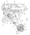
- an articulated shaft holder 7 is provided on the attachment 4, which advantageously consists in the illustrated embodiment of a multi-articulated and telescopic articulated arm 19 which is attached at one end to the Schnellkuppelrahmen 5 is and with its other end the connector 9 of the propeller shaft 8 stops.
- the cardan shaft holder does not have to consist of a single strut.
- the cardan shaft holder can also be multi-brace in the manner of a double-layered bed or a tripod, or in the form of a frame or support. The drawn one-armed design, however, is very compact.
- the articulated arm 19 extends in the illustrated embodiment approximately centrally from the top of the Schnellkuppelrahmens 5 sloping to the tractor 2 out of Schnellkuppelrahmen 5 away.
- the propeller shaft holder 7 comprises at its hinge shaft end a holding piece 20 which surrounds the connecting piece 9 of the propeller shaft 8.
- the connecting piece 9 is rotatably mounted on the holding piece 20 by a pivot bearing, preferably in the form of a plain bearing or a rolling bearing, namely the intended intended axis of rotation of the connector 9.
- the connector 9 is axially fixed and also kippfest on the holding piece 20 stored.
- the said holding piece 20 of the propeller shaft holder 7 is multi-axially articulated connected to the remaining body of the propeller shaft holder 7.
- FIG. 2 shows, two pivot joints 10 and 11 are provided between the holding piece 20 and the articulated arm 19, which together ensure the multi-axis pivotability of the holding piece 20.
- the articulated arm 19 is also multi-axially hinged at its Schnellkuppelrahmen ingredient end of the Schnellkuppelrahmen 5, wherein also two pivot joints 12 and 13 are provided, see. FIG. 2 ,
- each inhibiting devices 15 are integrated, which allow the action of a predetermined load, the corresponding pivotal movements of the propeller shaft holder, but hold the cardan shaft holder rigidly in the respective position when this predetermined external load is not achieved.
- the inhibitors 14 are in particular designed such that alone the weight of the propeller shaft 7 and the propeller shaft 8 is not sufficient to cause a pivoting of the pivot joints 10, 11, 12 or 13, but that only a significant additional load allows adjustment of the propeller shaft position.
- the inhibiting devices 14 can be dimensioned with respect to the limit force such that a manual adjustment of the position is possibly still possible under diverse gripping.
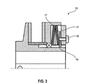
- the inhibiting devices 14 are formed by holding elements 15 in the form of friction brakes 16 and overload clutches, as they FIG. 3 shows.
- These friction brakes 16 advantageously comprise two mutually rotatable connecting pieces, between which mutually tensioned friction elements 17 are provided, which inhibit the rotation of the two connecting pieces, as long as an applied torque remains below a predetermined limit torque.
- adjusting means 17 are provided, for example in the form of a screw, by means of which the inhibiting force can be variably adjusted.
- FIG. 3 shows, directly to the pivot joints 10, 11, 12 and 13 of the propeller shaft holder 7, wherein in the illustrated embodiment, the pivot axes of said pivot joints pass through the inhibiting elements 15, ie the inhibitors 15 sit directly on the pivot axes.
- the propeller shaft 8 of the attachment 4 is aligned with its connecting piece 9 by hand when driving the Schnellkuppelrahmens 5 and the counter frame 6, so that the propeller shaft 8 to the PTO 23 of the tractor 2 can drive.
- relative movements occur between the propeller shaft 8 and the quick coupling frame 5, which is, for example, the result of adjusting movements of the machine body for ground adaptation or lifting of the attachment via the three-point linkage of the machine body Tractor 2 may be, the propeller shaft holder 7 automatically adjusts.
- the inhibiting force of the inhibiting devices 14 is overcome, so that the joints 10, 11, 12 or 13 can move accordingly.
- the articulated arm 19 is itself variable in length, in particular telescopically designed to allow also corresponding changes in length.
- this degree of freedom of the propeller shaft holder 7 is associated with a corresponding inhibiting device 14, for example in the form of a friction brake 16, the in FIG. 2 is designed as a spring-biased device.
- the position of the propeller shaft 8 including its connecting piece 9 of the propeller shaft holder 7 is when loosening the counterframe 6 from the quick coupling frame 5 and the removal of the connector 9 of the propeller shaft 8 of the tractor-side PTO frozen, so to speak.
- the inhibiting devices 14 fix the hinge points 10, 11, 12 and 13 of the propeller shaft holder 7, so that the connecting piece 9 of the propeller shaft 8 remains just in the position that is precisely aligned with the PTO 23 of the tractor 2 when the tractor 2 with the attached thereto Counter frame 6 is driven again on the Schnellkuppelrahmen 5 to couple the attachment 4 again.
- FIG. 4 results in the propeller shaft holder 7 even without the use of a Schnellkuppelrahmens 5 advantageously facilitate the coupling of the attachment 4 considerably.
- the attachment 4 may for this purpose have a plurality of articulation points 26, which may be provided on the machine frame 3 or an associated attachment block, cf.
- FIG. 4 At the articulation points 26, the links of the articulation, in particular a known Dreiticiananlenkung be articulated, by which the attachment 4 is mechanically connected to the tractor 2.
- FIG. 4 shows, the propeller shaft holder 7 is articulated with its one end on the machine frame 3 and an associated machine frame fixed part.
- the execution corresponds to FIG. 4 in particular with regard to the design of the cardan shaft holder of the embodiment described above FIG. 2 and 3 ,
Landscapes
- Life Sciences & Earth Sciences (AREA)
- Engineering & Computer Science (AREA)
- Mechanical Engineering (AREA)
- Soil Sciences (AREA)
- Environmental Sciences (AREA)
- Agricultural Machines (AREA)
Applications Claiming Priority (1)
| Application Number | Priority Date | Filing Date | Title |
|---|---|---|---|
| DE200710018319 DE102007018319A1 (de) | 2007-04-18 | 2007-04-18 | Landwirtschaftliches Anbaugerät |
Publications (2)
| Publication Number | Publication Date |
|---|---|
| EP1982580A2 true EP1982580A2 (fr) | 2008-10-22 |
| EP1982580A3 EP1982580A3 (fr) | 2011-06-01 |
Family
ID=39673387
Family Applications (1)
| Application Number | Title | Priority Date | Filing Date |
|---|---|---|---|
| EP08003494A Withdrawn EP1982580A3 (fr) | 2007-04-18 | 2008-02-26 | Elément auxiliaire agricole |
Country Status (2)
| Country | Link |
|---|---|
| EP (1) | EP1982580A3 (fr) |
| DE (1) | DE102007018319A1 (fr) |
Cited By (3)
| Publication number | Priority date | Publication date | Assignee | Title |
|---|---|---|---|---|
| WO2018119388A1 (fr) * | 2016-12-22 | 2018-06-28 | Polaris Industries Inc. | Fixation rapide de prise de force pour un véhicule utilitaire |
| EP3354122A1 (fr) * | 2017-01-25 | 2018-08-01 | Deere & Company | Ensemble de support de prise de puissance d'outil de travail |
| US10794457B2 (en) | 2017-08-25 | 2020-10-06 | Blount, Inc. | Power take off driveline lift and coupling assist device |
Citations (1)
| Publication number | Priority date | Publication date | Assignee | Title |
|---|---|---|---|---|
| DE4213069C1 (fr) | 1992-04-21 | 1993-09-23 | Friedrich Moertl Schleppergeraetebau Gmbh, 97737 Gemuenden, De |
Family Cites Families (5)
| Publication number | Priority date | Publication date | Assignee | Title |
|---|---|---|---|---|
| DE1159677B (de) * | 1956-11-30 | 1963-12-19 | Massey Harris Ferguson Inc | Einrichtung zum Anhaengen und Antreiben eines an einen Ackerschlepper anzuhaengendenlandwirtschaftlichen Geraetes |
| BE677842A (fr) * | 1965-03-16 | 1966-08-01 | ||
| DE4242995C2 (de) * | 1992-12-18 | 1997-01-16 | Walterscheid Gmbh Gkn | Kuppelvorrichtung zum Verbinden eines Traktors mit einem Gerät |
| AT403640B (de) * | 1996-08-01 | 1998-04-27 | Raiffeisenverband Salzburg Reg | Schnellkupplung zum anbau eines arbeitsgerätes an einem schlepper |
| US7278502B2 (en) * | 2004-09-15 | 2007-10-09 | Deere & Company | Implement and power take off attachment system |
-
2007
- 2007-04-18 DE DE200710018319 patent/DE102007018319A1/de not_active Withdrawn
-
2008
- 2008-02-26 EP EP08003494A patent/EP1982580A3/fr not_active Withdrawn
Patent Citations (1)
| Publication number | Priority date | Publication date | Assignee | Title |
|---|---|---|---|---|
| DE4213069C1 (fr) | 1992-04-21 | 1993-09-23 | Friedrich Moertl Schleppergeraetebau Gmbh, 97737 Gemuenden, De |
Cited By (5)
| Publication number | Priority date | Publication date | Assignee | Title |
|---|---|---|---|---|
| WO2018119388A1 (fr) * | 2016-12-22 | 2018-06-28 | Polaris Industries Inc. | Fixation rapide de prise de force pour un véhicule utilitaire |
| US10843565B2 (en) | 2016-12-22 | 2020-11-24 | Polaris Industries Inc. | PTO quick attach for vehicle |
| EP3354122A1 (fr) * | 2017-01-25 | 2018-08-01 | Deere & Company | Ensemble de support de prise de puissance d'outil de travail |
| US10343518B2 (en) | 2017-01-25 | 2019-07-09 | Deere & Company | Work implement PTO support assembly |
| US10794457B2 (en) | 2017-08-25 | 2020-10-06 | Blount, Inc. | Power take off driveline lift and coupling assist device |
Also Published As
| Publication number | Publication date |
|---|---|
| DE102007018319A1 (de) | 2008-10-23 |
| EP1982580A3 (fr) | 2011-06-01 |
Similar Documents
| Publication | Publication Date | Title |
|---|---|---|
| EP1252808B1 (fr) | Dispositif faucheur | |
| EP1205097B1 (fr) | Unité autonivelleuse de timon et bout en chape | |
| DE3439048A1 (de) | Kraftheber fuer ein hubgeraet | |
| DE4019948C2 (de) | Landwirtschaftliches Anhängegerät | |
| DE2500857A1 (de) | Nutzfahrzeug mit mindestens einer hebevorrichtung | |
| DE69531750T2 (de) | Heuwerbungsmaschine | |
| DE102007018319A1 (de) | Landwirtschaftliches Anbaugerät | |
| EP1932414A1 (fr) | Faucheuse destinée à l'agencement frontal sur un véhicule agricole | |
| EP1886547A2 (fr) | Liaison d'un bras de levage sur un arbre de levage d'un système d'attelage trois points | |
| EP1769668B1 (fr) | Tête de récolte avec châssis pivotant pour machines agricoles | |
| DE1158304B (de) | Gelenkverbindung zwischen mehreren ueber eine mit einem Kreuzgelenk ausgeruestete und mit Tragrohren versehene Gelenkwelle angetriebenen Landmaschinen | |
| DE19608579C2 (de) | Anhängevorrichtung | |
| EP3311650B1 (fr) | Machine de fenaison pourvue d'un dispositif d'attelage modulaire | |
| EP3818798B1 (fr) | Dispositif de montage pour monter au moins deux machines de travail agricole à un tracteur ainsi que train de travaux pourvu de tracteur, de dispositif de montage et de machines de travail agricole | |
| DE102012220339B4 (de) | Einzugs- und Messertrommelzusammenbau für einen Feldhäcksler | |
| EP4344528B1 (fr) | Tête de récolte à montage frontal sur une récolteuse dotée d'une unité de broyage | |
| EP3753385A1 (fr) | Structure porteuse pour le raccordement de deux accessoires agricoles à un tracteur ainsi qu'accessoire agricole | |
| EP1714538B1 (fr) | Outil de travail | |
| EP4101276B1 (fr) | Appareil accessoire destiné au traitement du sol | |
| EP0809927B1 (fr) | Embrayage articulé et séparable, à griffes | |
| EP0480005A1 (fr) | Dispositif pour le montage en saillie d'outillages sur un tracteur | |
| DE3032111C2 (de) | Landwirtschaftliche Maschine | |
| EP3823430B1 (fr) | Appareil agricole pourvu d'une transmission à cardan | |
| DE69914151T2 (de) | Landmaschine | |
| EP2656709A1 (fr) | Appareil de travail du sol comprenant deux dispositifs de traitement du sol pouvant être reliés par un accouplement rapide |
Legal Events
| Date | Code | Title | Description |
|---|---|---|---|
| PUAI | Public reference made under article 153(3) epc to a published international application that has entered the european phase |
Free format text: ORIGINAL CODE: 0009012 |
|
| AK | Designated contracting states |
Kind code of ref document: A2 Designated state(s): AT BE BG CH CY CZ DE DK EE ES FI FR GB GR HR HU IE IS IT LI LT LU LV MC MT NL NO PL PT RO SE SI SK TR |
|
| AX | Request for extension of the european patent |
Extension state: AL BA MK RS |
|
| PUAL | Search report despatched |
Free format text: ORIGINAL CODE: 0009013 |
|
| AK | Designated contracting states |
Kind code of ref document: A3 Designated state(s): AT BE BG CH CY CZ DE DK EE ES FI FR GB GR HR HU IE IS IT LI LT LU LV MC MT NL NO PL PT RO SE SI SK TR |
|
| AX | Request for extension of the european patent |
Extension state: AL BA MK RS |
|
| RIC1 | Information provided on ipc code assigned before grant |
Ipc: A01B 71/06 20060101AFI20110428BHEP |
|
| STAA | Information on the status of an ep patent application or granted ep patent |
Free format text: STATUS: THE APPLICATION IS DEEMED TO BE WITHDRAWN |
|
| AKY | No designation fees paid | ||
| 18D | Application deemed to be withdrawn |
Effective date: 20110901 |
|
| REG | Reference to a national code |
Ref country code: DE Ref legal event code: R108 Effective date: 20120208 |