EP1982801A1 - Dispositif fonctionnel à liaison parallèle - Google Patents
Dispositif fonctionnel à liaison parallèle Download PDFInfo
- Publication number
- EP1982801A1 EP1982801A1 EP08153936A EP08153936A EP1982801A1 EP 1982801 A1 EP1982801 A1 EP 1982801A1 EP 08153936 A EP08153936 A EP 08153936A EP 08153936 A EP08153936 A EP 08153936A EP 1982801 A1 EP1982801 A1 EP 1982801A1
- Authority
- EP
- European Patent Office
- Prior art keywords
- movable member
- base
- parallel
- rotary
- rotary actuators
- Prior art date
- Legal status (The legal status is an assumption and is not a legal conclusion. Google has not performed a legal analysis and makes no representation as to the accuracy of the status listed.)
- Withdrawn
Links
Images


Classifications
-
- B—PERFORMING OPERATIONS; TRANSPORTING
- B25—HAND TOOLS; PORTABLE POWER-DRIVEN TOOLS; MANIPULATORS
- B25J—MANIPULATORS; CHAMBERS PROVIDED WITH MANIPULATION DEVICES
- B25J17/00—Joints
- B25J17/02—Wrist joints
- B25J17/0258—Two-dimensional joints
- B25J17/0266—Two-dimensional joints comprising more than two actuating or connecting rods
-
- Y—GENERAL TAGGING OF NEW TECHNOLOGICAL DEVELOPMENTS; GENERAL TAGGING OF CROSS-SECTIONAL TECHNOLOGIES SPANNING OVER SEVERAL SECTIONS OF THE IPC; TECHNICAL SUBJECTS COVERED BY FORMER USPC CROSS-REFERENCE ART COLLECTIONS [XRACs] AND DIGESTS
- Y10—TECHNICAL SUBJECTS COVERED BY FORMER USPC
- Y10T—TECHNICAL SUBJECTS COVERED BY FORMER US CLASSIFICATION
- Y10T74/00—Machine element or mechanism
- Y10T74/20—Control lever and linkage systems
- Y10T74/20207—Multiple controlling elements for single controlled element
Definitions
- the present invention relates to a parallel-link operational device.
- So-called parallel-link operational devices in which a plurality of actuators are mounted on a fixed member as a base so that links connected to output shafts of the respective actuators are driven in parallel to control a position and a posture of a movable members mounted on ends of the links, have been developed in a variety of forms.
- a parallel-link operational device that uses a rotary actuator that outputs rotational force as a drive power source
- a parallel-link operational device that provides three motors on the fixed member so that output shafts of the motors move along sides of an equilateral triangle formed by the fixed member and the output shafts of the motors and the movable members are connected in a parallel linkage structure, such that by controlling the driving of the three motors the posture (the horizontal orientation) of the movable member is held and its position is controlled ( JP-S63-501860-A ).
- an invention that relates to a parallel robot having six degrees of freedom is also known, in which two motors are disposed opposite each other, links are provided on every other side of a hexagonal pedestal and connected to the output shafts of the motors so that the output shafts of the motors are parallel to the sides of a hexagonal pedestal, an arm is connected to the ends of the links, a single bracket (movable member) is connected to the end of the arm, and the position and posture of the bracket (the movable member) is controlled by controlling the rotation position of the motors ( JP06-270077A ).
- the actuators are provided approximately parallel to the sides of the actuator base.
- the links are provided so as to swing in a direction approximately perpendicular to the sides of the fixed member base. Consequently, the swinging of power transmission units for driving the movable member, each of which is composed of link-joint-rod-joint, is performed in a plane that is at a right angle to the base side.
- FIG. 15 is a schematic diagram of the disposition of the movable member and the actuators of the conventional parallel-link operating device that uses rotary actuators.
- the movable member 100 and the base are parallel, and further, the centerline of the movable member 100 and the centerline of the base are shown as coinciding.
- only one of the links 101 and rods 102 of the power transmission unit that transmits power from the actuator, not shown, and are connected to the movable member are shown.
- the other end of the link 101 mounted on the output shaft of the actuator, not shown, is connected to the rod 102 by a joint, and the other end of the rod 102 is connected to the movable member 100 by a joint.
- FIG. 16 is a diagram illustrating the disposition of the actuator and the movable member shown in FIG. 15 , as seen from a direction perpendicular to a plane of rotation 103 of the link 101.
- the plane of rotation 103 is parallel to the direction of radiation outward from the center of the base.
- the movable member 100 of the rotary-type parallel-link operational device is spatially supported by a plurality of power transmission units (links 101, rods 102, and the like), and a force acting on the movable member 100 is borne by the power transmission unit.
- a force acting on the movable member 100 is borne by the power transmission unit.
- the movable member 100 With respect to the exerted external force, if the load bearing capacity of the power transmission unit is large, the movable member 100 is supported rigidly; if the load bearing capacity of the power transmission unit is small, the movable member 100 is supported flexibly.
- the load bearing capacity of the power transmission unit changes depending on an angle of tilt of the power transmission unit with respect to the plane of the movable member 100, that is, the angle formed by a line joining the two ends of the rod 102 and the plane of the movable member 100 (in FIG. 16 , angle ⁇ or ⁇ ).
- angle ⁇ or ⁇ the angle formed by a line joining the two ends of the rod 102 and the plane of the movable member 100.
- the angles of tilt of the power transmission units change depending on the position and posture of the movable member 100. If the angles of tilt of the power transmission units are each different, then it is possible that if one power transmission unit load bearing capacity diminishes the load may be borne by the remaining power transmission units. However, in a case in which all the power transmission units are tilted at the same angle as described above, the load capacities of all the power transmission units change in the same way and thus the total load bearing capacity changes. In particular, as the angles of tilt of the power transmission units approach a right angle, that is, as the power transmission units approach being parallel, the load bearing capacity with respect to the external force acting horizontally on the movable member 100 decreases.
- the angle of rotation of the link 101 will be either A or B shown in FIG. 16 , depending on which the angle thereof with respect to the movable member 100 of the rod 102 will be either ⁇ or ⁇ .
- the location of the center of rotation is usually further outside than the movable member 100 rod connection points (in a direction away from the center of the base)
- the rod angle ⁇ when the rod 102 comes inside from the base center is always greater than the rod angle ⁇ when the rod 102 comes inside from the base center.
- ⁇ approaches a right angle, and thus is at a disadvantage with respect to an external force in the horizontal direction. Therefore, only arm angle A can be selected.
- the joint portion connecting the rod 102 and the link 101 protrudes outside the base.
- the present invention solves a problem of links of a linkage mechanism protruding beyond a base in a parallel-link operational device.
- a parallel-link operational device of the present invention comprises: a base; a movable member on which an end effector is attached; a plurality of rotary actuators fixedly mounted at respective predetermined positions on the base such that axes of output shafts of the rotary actuators extend substantially radially from a center of the base; and a link mechanism for operatively connecting the respective output shafts of the rotary actuators to the movable member so that a position and/or a posture of the movable member is controlled by the rotary actuators.
- the parallel-link operational device may further comprise an additional actuator mounted on the base for controlling a posture of the end effector, a rotary shaft provided at the movable member and connected with the end effector, and a rotational-force transmission mechanism for transmitting a rotational force of the additional actuator to the rotary shaft.
- an additional actuator mounted on the base for controlling a posture of the end effector
- a rotary shaft provided at the movable member and connected with the end effector
- a rotational-force transmission mechanism for transmitting a rotational force of the additional actuator to the rotary shaft.
- six of the rotary actuators may be provided so that the position and the posture of the movable member are controlled, and the posture of the end effector with respect to the movable member is controlled by the additional actuator.
- three of the rotary actuators may be provided and the link mechanism may comprise parallel linkages so that the position of the movable member is controlled by the three rotary actuators, and the posture of the end effector with respect to the movable member is controlled by the
- the plurality of rotary actuators may comprise a first three actuators that actuate a first movable member on which a first end effector is mounted, and a second three actuators that actuate a second movable member on which a second end effector is mounted to be opposite the first end effector.
- the link mechanism may comprise parallel linkages for operatively connecting the first movable member and the first three rotary actuators, and linkages for operatively connecting the second movable member and the second three rotary actuators for controlling the posture of the second movable member.
- the parallel-link operational device may further comprise a support post provided on a pedestal and rotatably supporting the second movable member by a spherical joint, a rotary shaft provided at the first movable member and connected with the first end effector, an additional actuator mounted on the base for controlling a posture of the first end effector, and a rotational-force transmission mechanism for transmitting a rotational force of the additional actuator to the rotary shaft.
- the rotary actuators may be arranged so that the axes of the output shafts radially extend at equal intervals about the center of the base.
- the rotary actuators may be arranged so that distal ends of the output shaft are directed toward the center of the base.
- the rotary actuators may be arranged so that distal ends of the output shafts are directed away from the center of the base, and have covers for preventing links of the link mechanism fixed to the output shafts from being exposed outside.
- the rotary actuators may be arranged so that the axes of the output shafts are inclined with respect to the base.
- the rotary actuators may be mounted on mounting members arranged vertically downward from the base.
- the rotary actuators may be mounted on mounting members arranged vertically upward from the base.
- Covers may be provided to connect the mounting members with one another.
- the rotary actuators may have speed reducers.
- Swinging motions of links of the link mechanism are made parallel to sides of the base, and the area through which the links swing is made to be within an area covered by the base.
- the link mechanism can be prevented from contacting or entangling operators or nearby objects.
- flat-shaped actuators are used, an increase in the size of the parallel-link operational device can be prevented.
- FIG. 1 is a diagram showing essential portions of a parallel-link operational device of a first embodiment of the present invention.
- FIG. 2 is a diagram showing a perspective view from above of the parallel-link operational device of the first embodiment of the present invention.
- FIG. 3 is a diagram showing an end effector drive system of the first embodiment.
- This first embodiment is a parallel-link operational device with six degrees of freedom, in which a movable member 5 can be a set to any position and posture using six rotary actuators 6, and moreover, an rotary axis 17 fixedly mounted on the movable member 5 can be continuously rotated using a single end effector posture control actuator 7 fixedly mounted on a base 4.
- the base 4 of the parallel-link operational device 1 is supported by a plurality of pillars 8 fixedly mounted on a pedestal 3.
- the face 4 is formed in the shape of a hexagon, and has actuator mounting members 9 suspended from each side thereof.
- a position/posture control rotary actuator 6 for controlling the position and posture of the movable member 5.
- a single end effector posture control actuator 7 (this actuator also is configured as a rotary type like the position/posture control rotary actuators 6).
- the actuators 6 are rotary actuators for controlling the position and posture of the movable member 5.
- Links 11 are fixedly mounted on rotary output shafts of the rotary actuators 6 so as to be able to rotate as a single unit together with the rotary output shafts 12.
- the rotary actuators 6 for controlling the position and posture of the movable member 5 are disposed to so that their rotary output shafts 12 are perpendicular to the sides of the hexagonal base 4 radially at equal intervals about the center of the base 4, and moreover, pointing toward the center the base 4.
- the rotary actuators 6 and the movable member 5 are connected by power transmission units.
- the power transmission units are each composed of the link 11 that is fixedly mounted on the rotary output shaft 12, a rod 10 one end of which is connected to the link 11 through a joint 13, and a joint 14 that connects the other end of the rod 10 to the movable member 5.
- a rotational-force transmission means 15 is connected through a joint 19 to the rotary output shaft of the end effector posture control rotary actuator 7 mounted at the center of the base 4, to the other end of which rotational-force transmission means 15 is connected a rotation mechanism 16 through a joint 18, with an end effector 20 mounted on an rotary axis 17 of the rotation mechanism 16 so as to protrude toward an opposite side of the movable member 5.
- the rotational-force transmission means 15 is configured as an extendible and contractible shaft, itself configured as a spline coupling composed of a shaft 15a having spline holes and a shaft 15b having spline teeth that engage the spline holes.
- the joints 13, 14 provided at both ends of the rod 10 are configured such that, if one joint has two degrees of freedom, the other joint has three degrees of freedom, for a total of five degrees of freedom.
- the joints 18, 19 mounted at both ends of the rotational-force transmission means 15 are configured as joints of two degrees of freedom.
- the position/posture rotary actuators 6 By driving the position/posture rotary actuators 6, the position in three-dimensional space (position along orthogonal X, Y, and Z axes) of the movable member 5 and the posture of the movable member 5 are controlled via the links 11, the joints 13, the rods 10, and the joints 14.
- the end effector invitation control actuator 7 and controlling the rotation position of the rotary axis 17 of the rotation mechanism 16 through the joint 19 the rotational-force transmission means 15, and the joint 18, and controlling the rotation position of the end effector 20, various operations are carried out.
- the rotational-force transmission means 15 that connects the rotary output shaft of the end effector posture control actuator 7 provided on the base 4 with the rotation mechanism 16 on the movable member 5 extends and contracts, and moreover, the rotational-force transmission means 15 and the movable member 5 linkage, and the rotational-force transmission means 15 and the actuator 7 rotary axis linkage, are both effected by joints , 18, 19 of two degrees of freedom, and therefore, even when the position and posture of the movable member 5 changes, the rotation position of the end effector 20 can be controlled with the actuator 7. Moreover, this actuator 7 is provided on the base and not on the movable member 5, and therefore the movable member 5 can be made lightweight.
- the position/posture control rotary actuators 6 are fixedly mounted on the base 4 so that the rotary output shafts 12 are directed radially toward the center of the base 4, and the links 11 fixed to the rotary output shafts 12 rotate in planes that are perpendicular to the axes of the rotary output shafts 12.
- the position/posture control rotary actuators 6 are mounted on the actuator mounting members 9 depending vertically downward from the sides of the octagonal base 4 and are each disposed perpendicularly to the center of the octagon so that the rotary output shafts 12 of the position/posture control rotary actuators 6 point toward the center of the base 4, with the links fixedly mounted on the rotary output shafts 12 and rotating in planes parallel to the respective sides of the octagon.
- the lengths of the sides of the octagonal base 4 may be twice the lengths of the links 11, so that the base 4 itself and does not become especially large.
- the conventional parallel-link operational device that swings in a direction perpendicular to the sides of the base, it can be seen that the conventional device, because the plane of rotation of the links is perpendicular to the plane of the sides of the base, the connecting points between the links and the rods always protrudes outside the base area.
- a flat actuator having a large diameter and a short total length is used.
- the actuator is configured as a flat actuator whose length in a direction perpendicular to an axial direction is greater than its length in a direction of the rotary output shaft.
- this actuator is configured as a motor, for example, an electromagnetic actuator or a rotary type of electrostatic actuator and composed of multiple layers of rotors and stators having multiple electrodes as described in JP-2005-278331-A may be used.
- end effector posture control actuator 7 may also be configured as a flat actuator like the movable member position/posture control rotary actuator 6, and in this embodiment an example using the same actuator is shown.
- actuators having decelerators inside may be used for these rotary actuators 6, 7.
- FIG. 4 is a diagram showing essential portions of a parallel-link operational device of a second embodiment of the present invention.
- FIG. 5 is a diagram showing a perspective view from above in the second embodiment with base, pillar, and pedestal removed. It is to be noted that, in FIG. 4 and FIG. 5 , the same reference characters are given to elements that are the same as those in the first embodiment.
- the second embodiment is a parallel-link operational device having four degrees of freedom that can move in three directions (that is, positions on orthogonal X, Y, and Z axes in three-dimensional space) while holding the posture of the movable member 5 constant with respect to the base 4 using three position control rotary actuators 6, and can control the rotation and rotational position of the end effector mounted on the rotary axis 17 by rotating the rotary axis 17 of the rotation mechanism 16 fixedly mounted on the movable member 5 using a single end effector posture control actuator 7 fixedly mounted on the base 4.
- the rotary actuators 6 for controlling the position of the movable member 5 are disposed at equal intervals radially about the center of the base so as to have their rotary output shafts perpendicular to three sides (that is, every other side) of the octagonal base 4.
- the movable member 5 is connected to each of the rotary output shafts 12 of the three rotary actuators 6 for position control via power transmission units each configured as a parallel linkage 21.
- links 22 are fixedly mounted on the rotary output shafts 12 of the rotary actuators 6, so as to be able to rotate as a single unit together with the road output shafts 12.
- two rods 23 are connected to the links 22 via joints 24, with the other end of the two rods 23 connected to the movable member 5 via joints 25.
- the construction link 22 connecting part ⁇ rods 23 ⁇ movable member 5 connecting part ⁇ rod 23 is designed and disposed so as to correspond to the sides of a parallelogram, by which the parallel linkage 21 is formed.
- Three parallel linkages 21 are connected to the movable member 5, and therefore its posture is fixed.
- the connecting parts between the links 22 and the rods 23, and the connecting parts between the movable member 5 and the rods 23, are parallel to the base 4, and therefore the movable member 5 can always be maintained in a posture that is parallel to the base 4.
- the means for driving the end effector mounted on the rotary axis 17 of the rotation mechanism 16 provided on the movable member 5 is the same as that in the first embodiment, with the actuator 7 fixedly mounted on the base 4 drivingly controlling the end effector 20 via the joint 19, the rotational-force transmission means 15, the joint 18, and the rotary axis 17 of the rotation mechanism 16.
- the joints 18, 19 at both ends of the rotational-force transmission means 15 are joints of two degrees of freedom such as universal joints, with the rotational-force transmission means 15 able to transmit rotation even as the movable member 5 moves by transmitting the rotation of a spline coupling or the like and using the extendable and contractible element.
- FIG. 6 and FIG. 7 are diagrams illustrating essential portions of a third embodiment of the present invention.
- the differences between the third embodiment and the second embodiment are that the rotary actuators 6 for controlling the position of the movable member 5 are mounted on the base 4 in the reverse direction of the direction in which they are mounted in the second embodiment, and covers 26 are provided.
- the remainder of the configuration is the same as that of the second embodiment.
- FIG. 6 is a diagram showing a side view of a parallel-link operational device 2a
- FIG. 7 is a diagram showing a view looking up from the movable member side in the third embodiment shown in FIG. 6 .
- the three rotary actuators 6 that control the position of the movable member 5 are mounted on actuator mounting members 9 that depend vertically downward from and along every other side of the hexagonal base 4 in such a way that their rotary output shafts point outward from the center of the base 4.
- covers 26 that depend vertically downward from the base 4 so as to cover an area of movement of the links of the parallel linkages 21 are mounted on the sides of the hexagonal base on which the rotary actuators 6 are mounted.
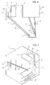
- FIG. 8 is a diagram showing essential portions of a parallel-link operational device 2b of a fourth embodiment of the present invention that is a variation of the second embodiment shown in FIG. 4 and FIG. 5 .
- the differences between this fourth embodiment and the second embodiment are that actuator mounting members 9a that mount the position control rotary actuators 6 are mounted on top of the base 4 so as to protrude upward therefrom, and openings 29 for enabling the rods 23 of the parallel linkages 21 to pass therethrough are provided in the base 4; the rest of the configuration is the same as that of the second embodiment. With such an arrangement, the work space and the parallel linkage space can be separated.
- operation as a parallel-link operational device is the same as that of the second embodiment.
- the links 22 mounted on the rotary output shafts of the rotary type actuators 6 of the parallel linkages 21 cannot protrude beyond the base 4, thereby enabling safety to be improved in the same way as with the second embodiment.
- FIG. 9 is a diagram showing essential portions of a fifth embodiment of the present invention, which varies the fourth embodiment described above.
- This fifth embodiment adds to the fourth embodiment covers 9b, but is otherwise the same as the fourth embodiment.
- the covers 9b composed of planar material so as to couple together the actuator mounting members 9a provided on and projecting from the base 4, the sides of the hexagonal base 4 are enclosed by the actuator mounting members 9a and the covers 9b, so that the area through which the links 22 of the parallel linkages 21 swing are not exposed, thus securing safety.
- safety may be further enhanced by providing a lid that covers the top of the area enclosed by the actuator mounting members 9a and covers 9b (the area through which the links 22 swing) to make the area an enclosed space. It is to be noted that that the remainder of the configuration and the operation of the parallel-link operational device are the same as the fourth embodiment.
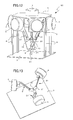
- FIG. 10 is a diagram showing essential portions of a sixth embodiment of the present invention.
- FIG. 11 is a diagram illustrating a coupling between one position control rotary actuator 6 and the movable member 5 in the sixth embodiment.
- a parallel-link operational device 2d of the sixth embodiment is a variation of the fourth embodiment shown in FIG. 8 , in which the three actuator mounting members 9a projecting from the base 4 in the fourth embodiment are tilted at a predetermined angle and the position control rotary actuators 6 that are mounted on the actuator mounting members 9a are also fixedly mounted at a predetermined angle. It is to be noted that the actuator mounting members 9a are not shown in FIG. 10 .
- the position control rotary actuator 6 is tilted at a predetermined angle ⁇ with respect to the horizontal plane (the plane of the base 4 or the plane of the pedestal 3), and thus the two rods 23 that form the parallel linkage 21 are tilted at the predetermined angle ⁇ and coupled to the link 22 and to the movable member 5 by joints 24, 25, respectively.
- connection locations of the rods 23 can be angled in the foregoing manner so as to support the parallel linkages, then, so long as no interference arises between the parallel linkages, and so long as safety is not adversely affected, there are no particular restrictions on the directions in which the position control rotary actuators 6 may be tilted.
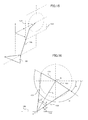
- FIG. 12 is a diagram showing essential portions of a seventh embodiment of the present invention.
- FIG. 13 is a diagram showing only a first movable member 5' whose position is controlled, the three rotary actuators 6 that control it, the parallel linkages 21 that control the position of the first movable member 5', and the pedestal 3 in the seventh embodiment.
- FIG. 14 is a diagram showing only a second movable member 5" whose posture is controlled, the three-year rotary actuators 6 that control it, posture control rods that control the posture of a support post 31 and the second movable member 5", and the pedestal 3.
- a parallel-link operational device of the seventh embodiment is a parallel-link operational device of six degrees of freedom having two movable members, the first movable member 5' whose position is controlled and the second movable member 5" whose posture is controlled.
- the first movable member 5' is kept in a fixed posture by the three parallel linkages 21, with only its position controlled by the three rotary actuators 6.
- the mechanism that controls the position of the first movable member 5' has the same configuration as that of the second embodiment shown in FIG. 4 and FIG. 5 , with the movable member 5 in the second embodiment being the first movable member 5' of the seventh embodiment.
- the second movable member 5" is connected to the support post 31 provided on the pedestal 3 through a spherical joint 32, and its position is fixed.
- the links 11 are fixedly mounted on the rotary output shafts 12 of the three rotary actuators 6, the links 11 and one end of the rods 10 are connected to each other via joints 13, not shown, and the other end of the rods 10 are connected to the second movable member 5" via joints 14, so that the power of the three rotary actuators 6 it is transmitted by the posture control rods 10, rotation is carried out around the three axes, and the posture of the second movable member 5" can be changed.
- the mechanism that drives the second movable member 5" differs from that of the first embodiment described with reference to FIGS.
- the end effector 20 is mounted on the rotary axis of the rotation mechanism 16 provided on the first movable member 5', and further, an end effector 33 is fixedly mounted on the second movable member 5" as well, opposite the end effector 20 on the first movable member 5', such that assembly work and the like is carried out by changing the relative positions of the two plates.
- the rotation mechanism 16 provided on the movable member 5 has a single rotary axis 17, and there is only one end effector posture control actuator 7 and only one rotational-force transmission means 15 that drive the rotary axis 17.
- end effector posture control actuators to drive the rotary axis and rotational-force transmission means to transmit the rotational force of the actuators to the respective rotary axes may be provided in numbers equal to the number of rotary axes thus provided.
Landscapes
- Engineering & Computer Science (AREA)
- Robotics (AREA)
- Mechanical Engineering (AREA)
- Transmission Devices (AREA)
- Manipulator (AREA)
Applications Claiming Priority (1)
| Application Number | Priority Date | Filing Date | Title |
|---|---|---|---|
| JP2007108727A JP2008264904A (ja) | 2007-04-17 | 2007-04-17 | パラレルリンク型作業装置 |
Publications (1)
| Publication Number | Publication Date |
|---|---|
| EP1982801A1 true EP1982801A1 (fr) | 2008-10-22 |
Family
ID=39540585
Family Applications (1)
| Application Number | Title | Priority Date | Filing Date |
|---|---|---|---|
| EP08153936A Withdrawn EP1982801A1 (fr) | 2007-04-17 | 2008-04-02 | Dispositif fonctionnel à liaison parallèle |
Country Status (4)
| Country | Link |
|---|---|
| US (1) | US20080257092A1 (fr) |
| EP (1) | EP1982801A1 (fr) |
| JP (1) | JP2008264904A (fr) |
| CN (1) | CN101288953A (fr) |
Cited By (1)
| Publication number | Priority date | Publication date | Assignee | Title |
|---|---|---|---|---|
| ITBO20090411A1 (it) * | 2009-06-24 | 2010-12-25 | U P B United Palletizer Bologna Societa A Res | Dispositivo per la movimentazione di articoli |
Families Citing this family (17)
| Publication number | Priority date | Publication date | Assignee | Title |
|---|---|---|---|---|
| JP4420959B2 (ja) | 2008-04-10 | 2010-02-24 | 村田機械株式会社 | パラレルメカニズム |
| DE102008001314A1 (de) * | 2008-04-22 | 2009-10-29 | Robert Bosch Gmbh | Vorrichtung zum Bewegen und Positionieren eines Gegenstandes im Raum |
| JP4598864B2 (ja) * | 2009-01-29 | 2010-12-15 | ファナック株式会社 | パラレルロボット |
| JP4659098B2 (ja) * | 2009-02-13 | 2011-03-30 | ファナック株式会社 | 3自由度を有する姿勢変更機構を備えたパラレルリンクロボット |
| EP2301726B1 (fr) * | 2009-09-24 | 2012-05-16 | CAMA 1 SpA | Tige télescopique pour robot industriel selon le concept delta |
| CN102049786A (zh) * | 2009-11-05 | 2011-05-11 | 鸿富锦精密工业(深圳)有限公司 | 转动机构及使用该转动机构的机器人 |
| CN101708611B (zh) * | 2009-11-09 | 2011-07-27 | 天津大学 | 一种具有三维平动一维转动的并联机构 |
| DE102010005586B4 (de) * | 2010-01-22 | 2012-03-29 | Martin Schwab | Hexapod |
| JP5528207B2 (ja) | 2010-05-19 | 2014-06-25 | Ntn株式会社 | リンク作動装置 |
| WO2012017722A1 (fr) * | 2010-08-02 | 2012-02-09 | 株式会社安川電機 | Mécanisme parallèle |
| DE102011003586A1 (de) * | 2011-02-03 | 2012-08-09 | Robert Bosch Gmbh | Multifunktionsbedienelement |
| EP2681016B1 (fr) * | 2011-02-28 | 2017-07-19 | Technische Universität Dresden | Robot parallèle et procédé de commande |
| JP5785055B2 (ja) * | 2011-11-07 | 2015-09-24 | Ntn株式会社 | リンク作動装置 |
| JP2013158874A (ja) * | 2012-02-03 | 2013-08-19 | Yaskawa Electric Corp | パラレルリンクロボットシステム |
| EP2829367B1 (fr) * | 2012-03-23 | 2019-03-06 | NTN Corporation | Dispositif d'actionnement d'articulation |
| JP6110620B2 (ja) * | 2012-09-26 | 2017-04-05 | キヤノン電子株式会社 | パラレルリンクロボット |
| JP6830626B2 (ja) * | 2016-12-20 | 2021-02-17 | 青島海爾洗衣机有限公司QingDao Haier Washing Machine Co.,Ltd. | 洗濯機 |
Citations (6)
| Publication number | Priority date | Publication date | Assignee | Title |
|---|---|---|---|---|
| JPS63501860A (ja) | 1985-12-16 | 1988-07-28 | ソジエバ ソシエテ アノニム | 空間で要素を運動させて位置決めするための装置 |
| JPH06270077A (ja) | 1992-04-24 | 1994-09-27 | Toyoda Mach Works Ltd | パラレルロボット |
| US20050159075A1 (en) * | 2003-11-18 | 2005-07-21 | Hiroshi Isobe | Linkage system |
| JP2005278331A (ja) | 2004-03-25 | 2005-10-06 | Fanuc Ltd | 静電モータ |
| US20060213308A1 (en) * | 2005-03-22 | 2006-09-28 | Ross-Hime Designs, Inc. | Robotic manipulator |
| EP1854591A1 (fr) * | 2006-05-11 | 2007-11-14 | Jean-Marie Chenu | Robot parallèle |
Family Cites Families (7)
| Publication number | Priority date | Publication date | Assignee | Title |
|---|---|---|---|---|
| GB9615283D0 (en) * | 1996-07-20 | 1996-09-04 | Cerestar Holding Bv | A method for precoating of chewing gum and a composition for the application in the said method |
| US5979264A (en) * | 1997-03-13 | 1999-11-09 | Ross-Hime Designs, Incorporated | Robotic manipulator |
| JPH11287303A (ja) * | 1998-04-02 | 1999-10-19 | Seishiro Munehira | パラレルリンク機構 |
| JP2000097306A (ja) * | 1998-09-24 | 2000-04-04 | Olympus Optical Co Ltd | パラレルリンク機構 |
| JP4290312B2 (ja) * | 2000-03-30 | 2009-07-01 | 三菱プレシジョン株式会社 | パラレル機構と、その制御方法及び制御装置 |
| JP4862974B2 (ja) * | 2000-10-18 | 2012-01-25 | 第一電気株式会社 | パラレルメカニズム |
| DE112004002721B4 (de) * | 2003-12-02 | 2013-07-25 | Robert Bosch Gmbh | Drehdurchführung eines Roboterarms |
-
2007
- 2007-04-17 JP JP2007108727A patent/JP2008264904A/ja not_active Withdrawn
-
2008
- 2008-04-02 EP EP08153936A patent/EP1982801A1/fr not_active Withdrawn
- 2008-04-04 US US12/062,747 patent/US20080257092A1/en not_active Abandoned
- 2008-04-16 CN CN200810091072.6A patent/CN101288953A/zh active Pending
Patent Citations (6)
| Publication number | Priority date | Publication date | Assignee | Title |
|---|---|---|---|---|
| JPS63501860A (ja) | 1985-12-16 | 1988-07-28 | ソジエバ ソシエテ アノニム | 空間で要素を運動させて位置決めするための装置 |
| JPH06270077A (ja) | 1992-04-24 | 1994-09-27 | Toyoda Mach Works Ltd | パラレルロボット |
| US20050159075A1 (en) * | 2003-11-18 | 2005-07-21 | Hiroshi Isobe | Linkage system |
| JP2005278331A (ja) | 2004-03-25 | 2005-10-06 | Fanuc Ltd | 静電モータ |
| US20060213308A1 (en) * | 2005-03-22 | 2006-09-28 | Ross-Hime Designs, Inc. | Robotic manipulator |
| EP1854591A1 (fr) * | 2006-05-11 | 2007-11-14 | Jean-Marie Chenu | Robot parallèle |
Non-Patent Citations (1)
| Title |
|---|
| CHOI H.B. ET AL: "Design and control of a novel 4-DOFs parallel robot H4", 2003 IEEE INTERNATIONAL CONFERENCE ON ROBOTICS AND AUTOMATION (ICRA '03) IN TAIPEI, TAIWAN, vol. 1, 14 September 2003 (2003-09-14) - 19 September 2003 (2003-09-19), PISCATAWAY, NJ, USA, pages 1185 - 1190, XP010667222, ISBN: 0-7803-7736-2, DOI: 10.1109/ROBOT.2003.1241753 * |
Cited By (1)
| Publication number | Priority date | Publication date | Assignee | Title |
|---|---|---|---|---|
| ITBO20090411A1 (it) * | 2009-06-24 | 2010-12-25 | U P B United Palletizer Bologna Societa A Res | Dispositivo per la movimentazione di articoli |
Also Published As
| Publication number | Publication date |
|---|---|
| JP2008264904A (ja) | 2008-11-06 |
| US20080257092A1 (en) | 2008-10-23 |
| CN101288953A (zh) | 2008-10-22 |
Similar Documents
| Publication | Publication Date | Title |
|---|---|---|
| EP1982801A1 (fr) | Dispositif fonctionnel à liaison parallèle | |
| ES2982531T3 (es) | Un brazo robótico industrial | |
| US4628765A (en) | Spherical robotic wrist joint | |
| US6418811B1 (en) | Robotic manipulator | |
| US8424411B2 (en) | Parallel robot | |
| JP2004216535A (ja) | 多関節ロボット | |
| CN102528817B (zh) | 一种三自由度并联机械手腕 | |
| JPH10225881A (ja) | オフセット回転関節及び該オフセット回転関節を有する多関節ロボット | |
| JP6605432B2 (ja) | 産業用ロボット | |
| JP2004529780A (ja) | 産業用ロボット | |
| CN103079775A (zh) | 吊挂式关节型机器人 | |
| JP4696384B2 (ja) | パラレルリンクロボット | |
| US6038940A (en) | Controlled robotic carrier | |
| WO2018088445A1 (fr) | Dispositif de travail et dispositif de travail de type à double bras | |
| CN114845840A (zh) | 用于以受控定向定位工具的敏捷机器人手臂 | |
| JP3419637B2 (ja) | 関節機構及びこれを使用するロボット | |
| JP2009045739A (ja) | パラレルリンク型作業装置 | |
| CN111168645A (zh) | 并联连杆机器人 | |
| JP2020104182A (ja) | パラレルリンクロボット | |
| KR20100041578A (ko) | 매달린 형태의 병렬기구구조 | |
| KR101766576B1 (ko) | 다자유도 구동장치 | |
| EP4371713A1 (fr) | Bras robotique en parallélogramme avec moteur comme contrepoids d'équilibrage | |
| KR20260011021A (ko) | 선형 동작부를 구비한 다자유도 구동 장치 | |
| KR102342053B1 (ko) | 최소한 하나의 구동축을 가지는 조인트 장치 | |
| JPH0336191A (ja) | 吊荷の姿勢制御装置 |
Legal Events
| Date | Code | Title | Description |
|---|---|---|---|
| PUAI | Public reference made under article 153(3) epc to a published international application that has entered the european phase |
Free format text: ORIGINAL CODE: 0009012 |
|
| AK | Designated contracting states |
Kind code of ref document: A1 Designated state(s): AT BE BG CH CY CZ DE DK EE ES FI FR GB GR HR HU IE IS IT LI LT LU LV MC MT NL NO PL PT RO SE SI SK TR |
|
| AX | Request for extension of the european patent |
Extension state: AL BA MK RS |
|
| 17P | Request for examination filed |
Effective date: 20081217 |
|
| AKX | Designation fees paid |
Designated state(s): DE |
|
| 17Q | First examination report despatched |
Effective date: 20090730 |
|
| STAA | Information on the status of an ep patent application or granted ep patent |
Free format text: STATUS: THE APPLICATION IS DEEMED TO BE WITHDRAWN |
|
| 18D | Application deemed to be withdrawn |
Effective date: 20091215 |