EP1982804B1 - Couteau à lame rétractable avec extension de lame actionnée à la poignée - Google Patents
Couteau à lame rétractable avec extension de lame actionnée à la poignée Download PDFInfo
- Publication number
- EP1982804B1 EP1982804B1 EP08153448A EP08153448A EP1982804B1 EP 1982804 B1 EP1982804 B1 EP 1982804B1 EP 08153448 A EP08153448 A EP 08153448A EP 08153448 A EP08153448 A EP 08153448A EP 1982804 B1 EP1982804 B1 EP 1982804B1
- Authority
- EP
- European Patent Office
- Prior art keywords
- blade
- handle
- utility knife
- shuttle
- box cutter
- Prior art date
- Legal status (The legal status is an assumption and is not a legal conclusion. Google has not performed a legal analysis and makes no representation as to the accuracy of the status listed.)
- Not-in-force
Links
- 238000005520 cutting process Methods 0.000 claims abstract description 55
- 230000006835 compression Effects 0.000 claims abstract description 27
- 238000007906 compression Methods 0.000 claims abstract description 27
- 230000033001 locomotion Effects 0.000 claims abstract description 26
- 230000005540 biological transmission Effects 0.000 claims abstract description 16
- 230000004044 response Effects 0.000 claims abstract description 6
- 230000008878 coupling Effects 0.000 claims description 19
- 238000010168 coupling process Methods 0.000 claims description 19
- 238000005859 coupling reaction Methods 0.000 claims description 19
- 210000003813 thumb Anatomy 0.000 claims description 13
- 210000003811 finger Anatomy 0.000 claims description 9
- 230000001681 protective effect Effects 0.000 claims description 8
- 210000005224 forefinger Anatomy 0.000 claims description 5
- 239000002184 metal Substances 0.000 claims description 5
- 238000012546 transfer Methods 0.000 claims description 5
- 238000000638 solvent extraction Methods 0.000 claims 2
- 230000003014 reinforcing effect Effects 0.000 claims 1
- 230000009977 dual effect Effects 0.000 abstract description 4
- 230000003252 repetitive effect Effects 0.000 abstract description 4
- 239000011111 cardboard Substances 0.000 description 9
- 206010049565 Muscle fatigue Diseases 0.000 description 6
- 230000009471 action Effects 0.000 description 6
- 239000000463 material Substances 0.000 description 6
- 230000000717 retained effect Effects 0.000 description 6
- 238000006243 chemical reaction Methods 0.000 description 5
- 230000006378 damage Effects 0.000 description 5
- 239000004033 plastic Substances 0.000 description 5
- 208000027418 Wounds and injury Diseases 0.000 description 4
- 230000008901 benefit Effects 0.000 description 3
- 208000014674 injury Diseases 0.000 description 3
- 238000013461 design Methods 0.000 description 2
- 238000003780 insertion Methods 0.000 description 2
- 230000037431 insertion Effects 0.000 description 2
- 230000014759 maintenance of location Effects 0.000 description 2
- 239000002991 molded plastic Substances 0.000 description 2
- 239000000123 paper Substances 0.000 description 2
- 239000011087 paperboard Substances 0.000 description 2
- 210000000707 wrist Anatomy 0.000 description 2
- 206010038584 Repetitive strain injury Diseases 0.000 description 1
- 229910000831 Steel Inorganic materials 0.000 description 1
- 229910001315 Tool steel Inorganic materials 0.000 description 1
- 206010052428 Wound Diseases 0.000 description 1
- 238000005452 bending Methods 0.000 description 1
- 230000002146 bilateral effect Effects 0.000 description 1
- 238000010276 construction Methods 0.000 description 1
- 230000003292 diminished effect Effects 0.000 description 1
- 238000006073 displacement reaction Methods 0.000 description 1
- 239000000428 dust Substances 0.000 description 1
- 230000013011 mating Effects 0.000 description 1
- 238000012986 modification Methods 0.000 description 1
- 230000004048 modification Effects 0.000 description 1
- 210000003205 muscle Anatomy 0.000 description 1
- 235000012771 pancakes Nutrition 0.000 description 1
- 230000000149 penetrating effect Effects 0.000 description 1
- 239000002861 polymer material Substances 0.000 description 1
- 238000002360 preparation method Methods 0.000 description 1
- 238000011084 recovery Methods 0.000 description 1
- 230000009467 reduction Effects 0.000 description 1
- 238000010008 shearing Methods 0.000 description 1
- 239000010959 steel Substances 0.000 description 1
- 238000006467 substitution reaction Methods 0.000 description 1
- 239000002023 wood Substances 0.000 description 1
Images


Classifications
-
- A—HUMAN NECESSITIES
- A45—HAND OR TRAVELLING ARTICLES
- A45F—TRAVELLING OR CAMP EQUIPMENT: SACKS OR PACKS CARRIED ON THE BODY
- A45F5/00—Holders or carriers for hand articles; Holders or carriers for use while travelling or camping
- A45F5/02—Fastening articles to the garment
-
- A—HUMAN NECESSITIES
- A45—HAND OR TRAVELLING ARTICLES
- A45F—TRAVELLING OR CAMP EQUIPMENT: SACKS OR PACKS CARRIED ON THE BODY
- A45F5/00—Holders or carriers for hand articles; Holders or carriers for use while travelling or camping
- A45F5/02—Fastening articles to the garment
- A45F5/021—Fastening articles to the garment to the belt
-
- B—PERFORMING OPERATIONS; TRANSPORTING
- B25—HAND TOOLS; PORTABLE POWER-DRIVEN TOOLS; MANIPULATORS
- B25H—WORKSHOP EQUIPMENT, e.g. FOR MARKING-OUT WORK; STORAGE MEANS FOR WORKSHOPS
- B25H3/00—Storage means or arrangements for workshops facilitating access to, or handling of, work tools or instruments
- B25H3/006—Storage means specially adapted for one specific hand apparatus, e.g. an electric drill
-
- B—PERFORMING OPERATIONS; TRANSPORTING
- B26—HAND CUTTING TOOLS; CUTTING; SEVERING
- B26B—HAND-HELD CUTTING TOOLS NOT OTHERWISE PROVIDED FOR
- B26B29/00—Guards or sheaths or guides for hand cutting tools; Arrangements for guiding hand cutting tools
- B26B29/02—Guards or sheaths for knives
-
- B—PERFORMING OPERATIONS; TRANSPORTING
- B26—HAND CUTTING TOOLS; CUTTING; SEVERING
- B26B—HAND-HELD CUTTING TOOLS NOT OTHERWISE PROVIDED FOR
- B26B3/00—Hand knives with fixed blades
- B26B3/06—Scout or similar sheath knives
-
- A—HUMAN NECESSITIES
- A45—HAND OR TRAVELLING ARTICLES
- A45F—TRAVELLING OR CAMP EQUIPMENT: SACKS OR PACKS CARRIED ON THE BODY
- A45F5/00—Holders or carriers for hand articles; Holders or carriers for use while travelling or camping
- A45F5/02—Fastening articles to the garment
- A45F2005/025—Fastening articles to the garment with a holder or item rotatably connected to the fastening device, e.g. having a rotation axis perpendicular to the garment
- A45F2005/026—Fastening articles to the garment with a holder or item rotatably connected to the fastening device, e.g. having a rotation axis perpendicular to the garment with a pin having an enlarged head detachably connected to a fastening device, e.g. to a pin receiving slot
-
- A—HUMAN NECESSITIES
- A45—HAND OR TRAVELLING ARTICLES
- A45F—TRAVELLING OR CAMP EQUIPMENT: SACKS OR PACKS CARRIED ON THE BODY
- A45F5/00—Holders or carriers for hand articles; Holders or carriers for use while travelling or camping
- A45F5/1575—Holders or carriers for portable tools
Definitions
- This invention relates generally to utility knives, and in particular to hand-held box cutters of the type used in various trades and crafts to cut sheet material and to open cardboard boxes.
- Utility knives commonly known as box cutters, include a handle in which a blade is secured for cutting a variety of materials.
- Adjustable-blade utility knives in which a replaceable, single-edge blade having a very sharp cutting edge is slideably-retained within a handle assembly have found widespread use in a variety of industries, for a variety of tasks, for example, shipping-and-receiving, drywall construction, wallpapering and tile-laying.
- Tradesmen use such utility knives to cut paper stock, plastic sheeting, linoleum, carpets, thin wood panels, wall paper, banding straps, tape and sealed plastic sacks containing bulk materials.
- Stocking clerks use box cutters to open cardboard cartons, for example in grocery stores, supermarkets, convenience stores, restaurants and other retail establishments.
- a cardboard carton is generally held steady in front of the operator with one hand and is cut by pulling the knife with the other hand toward the operator across the top or sidewall of the carton. Because such use frequently involves quick hand movements, and the cardboard presents considerable resistance to cutting, hand and wrist muscle fatigue become a serious concern. Moreover, operator flesh wounds are likely when the knife blade travels free at the end of a cut and catches the operator's hand, fingers, arm, waist or leg. Consequently, special attention must be given to box cutter design features that will protect the operator who must work quickly and repetitively.
- Boxes containing goods are often cut along a top edge around the perimeter of the box to remove a top portion of the box, or around an end edge to remove an end portion, exposing the items therein. It is preferable to cut open the box without cutting the contents within the box. It may be difficult, undesirable, and impermissible to sell merchandise that has been cut while opening the shipping box. For these reasons, it is preferable to make an accurate cut along the top edge of the box that avoids cutting the contents therein by cutting above the contents.
- persons opening boxes and stocking shelves are often under time constraints and economic constraints regarding the time and cost consumed in stocking the shelves. There is also a comfort factor to consider because a grocery stock clerk, for example, may make hundreds of cuts per day. Therefore, a box cutter needs to be easy to use repeatedly over long periods of time, without impairing operator performance or safety because of muscle fatigue.
- blade access and retention Another area of concern is blade access and retention.
- a replacement blade is retained by a keeper plate that is confined in a lower groove and an upper groove formed in the handle.
- the blade is removed from the knife by extending the keeper plate and blade assembly all the way forward out of the knife, which permits the blade to separate from its engagement with the keeper plate.
- the blade will simply fall from the handle by its own weight, resulting in a dropped blade.
- improved blade retention means needs to be provided for retaining the blade safely within the handle until such time as access is needed for blade replacement, so that the blade may be manually and safely removed by the operator.
- An edge guide on a box cutter provides a number of useful advantages.
- An edge guide allows an operator to quickly and accurately make a cut at a fixed distance from an edge.
- a guide allows the operator to repeatedly make cuts at a certain angle.
- a guide allows the operator to make more consistent cuts.
- An edge guide also allows the operator to make a cut with less effort and less energy exerted. For example, it is usually easier to make a cut with a pulling motion when the user can lean on the guide while pulling, as the guide slides across an edge.
- the guide allows the operator to make a cut at a precise location with less effort to maintain a stable position of the blade relative to the edge while cutting. Therefore, the use of an edge guide may allow the operator to make the same number of cuts per day more consistently while using less effort and energy, thereby reducing muscle fatigue.
- edge guides provide ways to accurately and quickly cut along an edge of a box at a certain distance from the edge and at a certain angle.
- box cutters are not only used to make edge cuts, but are also often used for other types of cuts, such as cutting a taped edge, where the fixed guard may interfere with or preclude other types of cuts.
- some edge guards do not provide safety features that will adequately protect a user during repeated rapid cuts.
- a need exists for a utility knife configured for reducing repetitive motion injuries caused by hand and wrist muscle fatigue and thumb manipulation to extend the blade, that will enable the operator to repeatedly, accurately and quickly cut open boxes without cutting the contents therein and without compromising the safety of the operator.
- a conventional box-cutter knife with automatic blade retraction has a housing forming a hand grip handle, a blade holder slidable in the housing, and a blade carried in the holder between a front position in which the blade projects forward from the front end of the housing and a retracted position in which the blade is enclosed within the housing.
- a spring is provided that continuously urges the blade and holder into the rear position.
- a thumb button is provided which allows the user to push the blade out and hold it extended for cutting action.
- a box cutter utility knife according to the invention is disclosed in the claims.
- An automatic blade-retracting box cutter utility knife of the present invention has a handle with ergonomic hand grip proportions for comfortable gripping and handling during repetitive cutting operations.
- the principal components of the knife that require operator access are mounted on the handle at locations that are symmetrically disposed relative to the cutting plane of the working blade.
- a blade-actuating hand-grip lever is mounted on the handle for movement about a pivotal axis.
- a blade shuttle is coupled to the hand-grip lever and is received in a guide channel formed in the handle for carrying a working blade from a rear retracted end position in which a working blade is wholly received in the handle, to a front extended end position in which a working blade is extended forward from the handle.
- the blade shuttle is extended in response to squeezing or gripping actuation of the hand-grip lever, and automatically retracts when the hand-grip lever is released.
- Extension and retraction forces are transferred from the hand-grip lever to a compression spring and to the blade shuttle via a power transmission assembly that includes a torque plate that is mounted for clockwise and counterclockwise rotation on the handle.
- the energy provided by hand-grip actuation is stored in a compression spring that is coupled between the handle and the hand-grip lever.
- the blade shuttle is retracted in response to expansion of the compression spring when the hand-grip lever is released.
- a depth of cut adjustment assembly is integrated with the power transmission assembly. Depth of cut, or blade extension, is selectively set to a desired depth of cut by manual adjustment of a rotary dial, which limits pivoting travel of the gripping lever during hand grip actuation.
- Top access to a working blade and a replacement blade stored on the shuttle is provided on top of the handle for blade loading and security.
- the working blade and one or more replacement blades are securely retained in top loading compartments formed between the sidewalls of the blade shuttle.
- a window formed in the top of the handle provides operator access for loading and replacing blades. The window is closed by a blade cover that is pivotally attached to the handle, thereby providing a protective covering over the blade receiving compartment in a closed position, and providing operator access to the blade receiving compartment in an open position.
- the handle has a blade extension port that is wedge-shaped in profile, being narrow at the top and relatively wide at the bottom. During a cutting operation, the working blade is locked against deflection on both sides and along the top and bottom of the blade. This prevents buckling of the blade as the cutter blade is undergoing heavy cutting action.
- Dual edge guide members are mounted for independent extension and retraction movement, enabling use by left handed as well as right-handed operators.
- a fixed blade stub projects from the rear of the housing for quick tape cutting jobs.
- the exposed cutting edges and corners are relatively blunt for personal safety and product protection.
- the fixed blade stub is mounted on the butt end of the handle and can be used while the cutting blade is locked in the fully retracted position, thus improving operator safety when using the knife to perform tape cutting operations that do not require a sharp cutting edge.
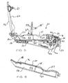
- FIG. 1 is a left side elevation view of a box cutter utility knife having an ergonomic handle and equipped with the cutter blade management features of my invention
- FIG. 2 is a top plan view thereof, showing the cutter blade and edge guides in the retracted position, and blade access cover in the closed position;
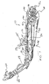
- FIG. 3 is a left side elevation view thereof, with the left handle sidewall removed, showing the blade shuttle, power transmission assembly and hand-grip lever in the at-rest, blade retracted position;
- FIG. 4 is a left side elevation view thereof, with the left handle sidewall removed, showing the blade shuttle extended, power transmission assembly and hand-grip lever actuated in the blade exposed position;
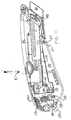
- FIG. 5 is a side elevation view similar to FIG. 3 , with the working blade access cover panel and replacement blade access cover panel in the unlatched, open access positions;
- FIG. 6 is a perspective view of a blade shuttle equipped with a top loading working blade compartment and a top loading replacement blade compartment;
- FIG. 7 is an enlarged perspective view similar to FIG. 5 showing details of the blade shuttle, hand-grip lever and power transmission assembly;
- FIG. 8 is an enlarged perspective view similar to FIG. 7 , with access door panels removed, showing a working blade and two replacement blades positioned for loading insertion into the blade receiving compartments of the blade shuttle;
- FIG. 9 is an enlarged front elevation view of the box cutter knife of FIG. 1 showing details of the blade extension port;
- FIG. 10 is an enlarged side elevation of a handle housing, which shows a flared blade guide surface which provides variable side support for a working blade;
- FIG. 11 is a right side elevation view of the box cutter utility knife of FIG. 1 , with the right handle sidewall removed, showing the left edge guide extended and the right edge guide filly retracted;
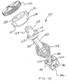
- FIG. 12 is an enlarged perspective view of a depth of cut adjustment assembly of my invention.
- FIG. 13 is an exploded perspective view of the depth of cut adjustment assembly of FIG. 12 ;
- FIG. 14 is a top perspective view of the depth of cut adjustment assembly of FIG. 12 ;
- FIG. 15 is an underside perspective view of the index coupling collar shown in FIG. 13 ;
- FIG. 16 is an underside perspective view of the rotary depth of cut adjustment dial shown in FIG. 13 ;
- FIG. 17 is an underside perspective view of the guide post coupling block shown in FIG. 13 ;
- FIG. 18 is left side elevation view of the box cutter utility knife of FIG. 1 inserted into a holster, and coupled thereto by a coiled lanyard;
- FIG. 19 is a bottom perspective view thereof.
- FIG. 20 is a top plan view thereof
- FIG. 21 is a cross sectional view thereof taken along line 21-21 of FIG. 20 ;
- FIG. 22 is a cross sectional view thereof taken along line 22-22 of FIG. 20 .
- a box cutter utility knife 10 of the present invention includes a handle 12 formed by a pair of molded plastic handle sections 14 and 16.
- the handle sections 14, 16 have bilateral symmetry along the cutting plane 18 of the working blade 20 and are connected together to enclose a cavity 22.
- the working blade 20 is held in a molded plastic blade shuttle 24 that is movable through a guide channel 25 formed along the handle sidewalls in an outward or forward direction to a fully extended position ( FIG. 4 ) and in an opposite inward or rearward direction to a retracted position ( FIG. 3 ).
- an exposed cutting edge 26 of the working blade can be engaged against a workpiece, for example, for cutting corrugated paperboard.
- the working blade 20 of the utility knife 10 is automatically retracted within the handle when the working blade is withdrawn from a cut, so it is less likely to inflict injury during use or when handled casually with the blade extended.
- the principal components of the utility knife 10 include the handle assembly 12 which covers the cutting edge of the working blade when it is not engaged against a cardboard container or other workpiece, the blade shuttle 24 which fits into the handle assembly 12, the working blade 20 which is retained and carried on the shuttle 24, a spring-loaded power transmission assembly 28 enclosed within the handle, and a hand-grip lever 30 which actuates the power transmission assembly.
- the handle sections 14, 16 form a handle body 12 having ergonomic hand grip proportions for comfortable gripping and handling during repetitive cutting operations.
- the blade-actuating hand-grip lever 30 is pivotally mounted on pivot pins 31, 33 received in sockets 35, 37 formed in the handle sections for movement about a pivotal axis 32.
- the blade shuttle 24 is mounted for longitudinal sliding reciprocal movement in the handle cavity 22 from a retracted rear end position ( FIG. 3 ) in which the working blade 20 is totally enclosed in the handle, to an extended front end position in which a portion of the working blade 20 projects forward from the handle.
- the blade shuttle 24 is extended in response to gripping actuation of the hand-grip lever 30 and retracts automatically upon release.
- the energy provided by hand-grip actuation is stored in a compression spring 34 that is coupled between the handle 12 and the hand-grip lever 30.
- the compression spring 34 has a coil profile in the form of a barrel, with large diameter coil turns centered on opposite sides between small diameter coil turns.
- the barrel spring 34 permits the assembly to be contained entirely within the handle, since the barrel spring will compress into a minimum dimension pancake stack profile upon full compression.
- the blade shuttle 24 is retracted by expansion of the compression spring 34 when the hand-grip lever is released.
- the handle body 12 has a curved top side 52, a curved underside 54, a butt end portion 50, a blade projection end portion 48, a first handle sidewall 14 and a second handle sidewall 16 forming a guide channel 25 between the handle body end portions, and a blade extension port 70 disposed on the blade projection end portion of the handle body and aligned with the guide channel.
- the extension and retraction forces are transferred from the hand-grip lever 30 to the compression spring 34 and to the blade shuttle 24 via the power transmission assembly 28 that includes a torque plate 36 that is mounted on a pivot pin 38 for clockwise and counterclockwise rotation within the handle cavity 22.
- the torque plate 36 includes a pair of torque transfer arms 40, 42 that are coupled to the blade shuttle 24 and to the hand-grip lever 30 by first and second toggle links 44, 46, respectively.
- the compression spring 34 upon hand-grip actuation, the compression spring 34 is compressed simultaneously as the blade shuttle 24 is extended, and upon release of the hand-grip lever 34, the compression spring 34 expands, urging the hand-grip lever toward its at-rest position ( FIG. 3 ) and returning the blade shuttle 24 to its rear retracted end position.
- the torque transfer action and compressed spring reaction of the power transmission assembly 28 ensure that the working blade 20 will be extended and will stay extended so long as the working blade is held against the object being cut.
- the power transmission assembly provides a mechanical advantage in that only a relatively small amount of hand grip force is needed to compress the spring 34 and maintain extension of the working blade while applying only moderate force against the object being cut, while at the same time, the reaction torque provided by the compression spring 34 is adequate to quickly retract the working blade 20 upon release of the hand-grip lever and disengagement from a work piece.
- the handle 12 is formed with ergonomic hand grip proportions.
- the blade shuttle is disposed generally in coplanar alignment with the working blade cutting plane 18.
- the power transmission assembly 28 and the torque plate 36 rotate clockwise and counterclockwise, generally in coplanar alignment with the blade shuttle 24 as it moves between the extended and retracted positions, thus reducing the required thickness size of the handle 12. This allows the handle to be gripped firmly and comfortably by an operator having an average size hand.
- the hand-grip lever 30 has sufficient length to engage all four fingers of the operator's hand, so that hand-grip actuation forces are distributed substantially uniformly through all hand and finger muscles, thereby reducing muscle fatigue. This ergonomic arrangement also leaves the operator's thumb free to grip the handle sidewall and tightly clamp it against the operator's forefinger, thus holding the knife 10 steady during cutting operations.
- the handle 12 has a generally wedge profile, having a relatively narrow cross section at the front or nose blade extension end portion 48 and relatively wider cross section at the rear or butt end portion 50 of the handle, and slightly curved along the top side 52 and bottom side 54.
- the upper and lower curved handle portions conform generally to the natural profile curvature of an operator's grip when the operator's hand and fingers are curled in gripping engagement around the handle 12, and the hand grip lever 30 extending longitudinally along the underside 54 of the handle body thereby allowing independent thumb and forefinger movement and gripping engagement of the handle body between the thumb and forefinger simultaneously with finger gripping engagement about the hand grip lever 30.
- This configuration conforms generally with the natural wedge-shaped, curved gripping profile provided by the operator's hand, fingers and thumb in the operative, gripping engagement around the handle body.
- the knife 10 is provided with top loading blade access and security.
- the working blade 20 is securely retained in a pocket or compartment 56 formed between the sidewalls 58, 60 of the blade shuttle 24.
- the working blade pocket 56 has a working blade loading aperture 62 in which a working blade is inserted and released while the handle is held upright and level, a shown in FIG. 8 .
- the working blade 20 is double-ended and is intersected by an index notch 64 between two cutting edges 26A, 26B.
- the index notch 64 is engaged with a rib segment on the floor of the working blade pocket, which accurately positions the working blade in the shuttle.
- the loading aperture 62 is closed and secured by a top panel door 66 that is pivotally coupled to the housing on or near the nose portion 48.
- Each replacement cutter blades 21, 23 are securely retained in a replacement blade storage pocket 57 formed between the sidewalls 58, 60 of the blade shuttle 24 and in tandem with the working blade compartment 56.
- Each blade storage pocket has a top loading aperture through which the blades are inserted and withdrawn.
- the loading aperture 63 of the replacement blade storage pocket 57 is closed and secured by an interior panel door 59 that is pivotally coupled to the handle.
- the interior panel door is pivotally mounted on a central cross web 65 that extends between the handle sidewalls and provides a stable pivotal under-support for the internal storage cover panel door 59.
- the cross web also reinforces the shuttle sidewalls 58,60 to oppose deflection caused by hand grip pressure.
- the interior panel door 59 is covered and enclosed by the main closure panel door 66, which can be opened and closed independently of the interior panel door.
- the replacement blade storage pocket 57 is separated from the working blade pocket 56 by a central cross rib 61.
- the cross rib 57 stabilizes the working cutter blade 20 against longitudinal displacement, and reinforces the shuttle sidewalls 58, 60 to oppose deflection caused by hand grip pressure.
- the top blade cover panel door 66 provides a protective covering over the blade receiving compartment in the closed position.
- the top panel door is latched into the closed position by first and second resilient interlocking coupling members 67, 69 formed on the panel door 66 and the handle housing.
- the closure panel door 66 is reinforced by a metal reaction plate 68 ( FIG. 7 ).
- the metal reaction plate 68 is mounted on the underside of the top closure panel door for engaging the top of the working blade 20 when the top panel door is closed, which keeps the working blade confined in the shuttle compartment 56 and forms a hard shield that opposes direct contact by the top of the working blade 20 against the top panel door.
- the metal shield 68 prevents structural damage to the closure panel door that would otherwise be caused by working blade gouging and cutting of the top panel door 66, which is formed of a durable, high strength plastic material, but which is relatively soft compared to the hardness of with the working blade, which is made of tool steel, approximately 0.017 inch thick (about 0.4318 mm).
- the handle 12 has a blade extension port or aperture 70 that is rectangular in profile.
- the blade extension port 70 provides a exit window for a wedge-shaped channel 72 formed by a pair of handle sidewall web portions 74, 76 that are outwardly flared from the blade extension port.
- the flared web portions provide a blade extension channel that is relatively narrow in lateral cross-section at the extension port 70 and relatively wide in lateral cross-section near the fully retracted position of the blade shuttle 24, at a longitudinal distance of about 0.125 inch inwardly from the front of the handle nose.
- the handle edge portions defining the front aperture 70 provide a lateral clearance of about 0.0025 inch (about 0.0635 mm) to about 0.0030 inch (about 0.0762 mm) on each side of the working blade at the aperture 70, and the flared side web portions 74, 76 provide a lateral clearance of about 0.0045 inch (0.1143 mm) to about 0.0050 inch (0.127 mm) on each side of the working blade at the terminal end 78 of each flared web portion.
- the working blade 20 is locked against deflection on both sides and along the top and bottom edges of the blade by the handle edge portions that frame the extension port 70 ( FIG. 9 ). This prevents buckling of the working blade as the blade undergoes heavy cutting action. Resistance during a cutting operation forces the working blade against the metal reaction plate 68, and into a narrow portion of the blade extension channel, to stabilize the blade and limit lateral deflection. The working blade 20 will retract into the enlarged rear area of the blade extension channel 72 where there is greater lateral clearance to accommodate smooth blade extension and retraction.
- the blade shuttle 24 carries the working blade 20 and one or more replacement blades 21, 23 in separate compartments 56, 57 that are aligned in tandem relation.
- the shuttle 24 is made of a durable, resilient plastic material that exhibits the property of shape memory recovery, which enables it to deflect and recover its straight configuration after undergoing compression, bending and torque forces during a cutting operation.
- the shuttle 24 has a blade pocket, formed by parallel sidewalls and a bottom floor wall. The pocket is open at the top to receive a replacement working blade, and open at the front to allow the working blade to project through the front blade extension port 70, thereby exposing the cutting edge 26 of the working blade 20.
- the handle sections 14, 16 are reinforced by a pair of planar web portions 84, 86 that extend from the handle sections on opposite sides of the blade shuttle.
- the web portions engage slidably against the blade shuttle sidewalls 58, 60.
- the web portions thereby provide a dust cover for the handle cavity 22 and shuttle compartments 56, 57, reinforce the handle sections against deflection caused by hand grip pressure, and prevent improper insertion of the working blade 20.
- dual edge cutting guide members 80, 82 are mounted for independent extension and retraction movement.
- the edge guide members 80, 82 are symmetrically disposed on laterally opposite sides of the blade extension port 70.
- This dual edge, symmetrical guide arrangement allows a right-handed or a left-handed operator to quickly and accurately make a cut at a fixed distance from a box edge and at a fixed angle.
- a first edge guide member is mounted on the right handle sidewall for extension and retraction relative to the blade projection end portion of the handle body, and a second edge guide member is mounted on the left handle sidewall for extension and retraction movement relative to the blade projection end portion of the handle body.
- Each edge guide member is mounted in inset pockets 83, 85 formed in the handle sidewalls, respectively, as shown in FIG. 9 .
- This symmetrical, inset mounting arrangement provides maximum blade view for left handed as well as right handed operators.
- a depth of cut adjustment assembly 90 is integrated with the power transmission assembly 28. Depth of cut, or blade extension, is set by limiting pivoting travel of the hand grip lever 30 during hand grip actuation.
- a spindle guide post 92 is mounted on a travel block bushing 94.
- the travel block bushing is pivotally coupled to the gripping lever 30 on pivot pins 96, 98.
- the travel block guide bushing 94 is intersected by a main bore 100 and one or more axially extending index pockets 102, 104, 106 of various depths that correspond to predetermined blade extensions.
- the opposite end of the spindle guide post 92 is mounted for rotary clockwise and counter-clockwise movement relative to the handle 12.
- a coupling collar 108 is pivotally mounted to the handle by radially projecting pivot pins 110, 112 that latch into pockets formed on the handle sidewall sections.
- the upper end of the guide post is fitted with latching pins 109, 111, 113 that are releasably engagable in detent pockets or slots 114, 116, 118 and 120 formed in the underside of the coupling collar 108.
- An elongated rib or spline 122 formed on the spindle guide post 92 extends through a bore 100 formed in the guide bushing for engagement in a selected one of the depth of cut index slots 100, 102, 104.
- the guide post is formed by a steel post enclosed within a jacket of high strength polymer material.
- the radially projecting pivot pins 110, 112 of the coupling collar 108 are received within a pair of pockets formed in the handle portions, thus preventing rotation of the coupling collar.
- the spline 122 is selectively engagable in each index slot 100, 102, 104. Depth of cut adjustment is made by manually rotating the spindle guide post 92 until the spline 122 is brought into registration with the desired depth of cut index slot.
- a manually operable depth of adjustment dial 130 is attached to the top of the spindle guide post 92. As the dial is rotated, the barrel spring 34 compresses, allowing the spindle post to turn and the spindle index spline 122 to advance to the next index slot.
- the dial is intersected by a bore 134 and includes a flat 136 for engaging a mating post 138 and flat 140 formed on top of the guide post 92.
- Window slots 140, 142 are formed in the housing on opposite sides of the dial 130. The edges of the dial project through the window slots, thereby providing convenient operator access to adjust the dial to a locked position (L), to minimum depth of cut position (No. 1), to a median depth of cut position (No. 2), to a maximum depth of cut position (No. 3).
- a triangular blade segment projects beyond the oblique margins at the front of the shuttle, thus exposing the cutting edge in this region.
- the cutting edge is positioned in parallel with the lower longitudinal edge of the shuttle and is offset only slightly above the lower edge of the knife.
- the exposed portion of the triangular blade segment corresponds with the maximum depth of cut, for example 5/16 inch, at the maximum setting "No. 3.”
- the depth of cut selection is maintained by the compression spring 34, which is mounted around the spindle guide post.
- the compression spring urges the coupling collar into engagement with the index spline of the spindle, which is received in detented latching engagement with one of the depth of cut index pockets formed on the travel block 94.
- the depth of cut is adjusted by moving the dial 130 to one of the four preset depth-of-cut positions: "No. 3" (blade fully extended), “No. 2" (intermediate), “No. 1” (minimum) and “L” (blade fully retracted and locked).
- the shuttle and blade assembly is slidably retained in the slide passage 25 formed between the handle sidewall webs and the top and bottom handle edges respectively.
- the working blade 20 is carried along with the shuttle, the depth of cut assembly being adjustably extendable and retractable in and out of the forward end of the handle to the preset positions by manual engagement of the index spline with one of the detent notches formed in the travel block.
- the detent notches are fixed angularly spaced positions providing a fully extended detent position No. 3 corresponding to at least a segment of the blade and its cutting edge projecting beyond the front end of the handle at a maximum depth of cut (utility depth of cut for cutting sheet stock, tie wraps, floor tile), a partially extended detent position No. 2 corresponding to a shorter segment of the blade and its cutting edge projecting beyond the front end of the handle at an intermediate depth of cut (for cutting a double ply thickness corrugated box), a partially extended detent position No.
- a fixed stub blade 150 projects from the rear or butt end portion 50 of the handle body 12 for performing quick tape cutting jobs.
- the exposed cutting edges and corners of the fixed stub blade are relatively blunt for personal safety and product protection, but are sufficient for shearing a taped union, for example along the top edges of box folding panels, which are typically sealed by a strip of high strength tape.
- the cutting edge cuts into the box sidewall, penetrating to the full extent of the projection of the blade segment beyond the handle.
- the blade is forced into the box sidewall until the oblique edges at the front end of the handle are pulled into contact against the box.
- the knife 10 is pulled along the box at approximately the same angle, and of course as the knife moves, its cutting edge slits the sidewall of the box.
- the compression spring 34 automatically returns the blade shuttle to the fully retracted position, thus preventing inadvertent blade contact with the operator immediately after the knife is disengaged during follow-through that accompanies rapid hand movements.
- a holster assembly 160 for the box cutter 10 provides for normal use of the box cutter in the workplace while keeping the box cutter in close proximity to the operator for ready use.
- the holster has a body substantially conforming to the shape of the box cutter 10, an open top end, and a closed bottom end.
- An expansion ring 166 connects the lanyard to the butt end of the knife, and the opposite end of the lanyard is connected to the holster 160 by another coupling ring 168.
- Each expansion ring is covered with a short shroud of shrink wrap tubing 170, 172.
- the shrouds 172, 174 discourage unauthorized removal fo the lanyard, and the shroud 172 provides a shield flap that shields the operator from inadvertent contact with the stub blade 150.
- Snap-fit detent couplings 176, 178 are formed on opposite sides of the holster. These detent couplings have rotary index members 180, 182 that engage index pins 87, 89 attached to the left and right edge guides 80, 82 when the knife is inserted into the holster.
- the detent couplings are rotatable to predetermined positions that engage the edge guides and automatically extend the edge guides to a predetermined offset extension length.
- the operator can set the coupling to accommodate right handed or left handed operation, and can also set the holster to automatically extend the edge guide by a preset amount upon withdrawal of the knife from the holster.
Landscapes
- Engineering & Computer Science (AREA)
- Mechanical Engineering (AREA)
- Life Sciences & Earth Sciences (AREA)
- Forests & Forestry (AREA)
- Knives (AREA)
Claims (27)
- Couteau utilitaire à lame rétractable du type incluant un corps-manche (12) ayant des portions de parois latérales définissant un canal de guidage (25), un porte-lame mobile (24) monté en vue d'un mouvement d'extension et de rétraction le long du canal de guidage (25) et mobile dans celui-ci entre une position de protection de lame jusqu'à une position d'exposition de lame dans laquelle une lame de travail (20) portée sur le porte-lame mobile (24) se projette à l'extérieur du corps-manche (12), un levier manuel (30) couplé au corps-manche pour un mouvement de pivotement depuis une position de repos dans laquelle le porte-lame mobile (24) est rétracté dans la position de protection jusqu'à une position d'utilisation dans laquelle le porte-lame mobile (24) est en extension à la position d'exposition de lame, un ensemble de transmission de couple (28) couplé de façon mobile entre le porte-lame mobile (24) et le levier manuel (30) pour convertir un mouvement du levier manuel (30) en un mouvement du porte-lame mobile (24),
caractérisé en ce que le couteau comprend : un bloc de compression (94) couplé au levier manuel (30) ; un pilier guide (92) disposé entre le boîtier-manche (12) et le bloc de compression, dans lequel le pilier guide (92) est monté en vue d'une rotation par rapport au corps-manche (12) ; un ensemble sélecteur de profondeur de coupe (90) attaché au pilier guide (92) ; et un ressort hélicoïdal de compression (34) disposé autour du pilier guide (92) et confiné en vue d'une compression et d'une expansion entre le corps-manche (12) et le bloc de compression (94) en réponse à un actionnement par préhension et un relâchement du levier manuel (30). - Couteau utilitaire à lame rétractable selon la revendication 1, dans lequel l'ensemble sélecteur (90) comprend un collier de couplage (108) qui est recoupé par une ou plusieurs fentes longitudinales d'indexation de profondeur de coupe qui correspondent à une ou plusieurs extensions de la lame ; le collier de couplage (108) est monté en vue d'un mouvement rotatif dans le sens des aiguilles d'une montre et dans le sens inverse aux aiguilles d'une montre sur le manche ; et le pilier guide (92) comprend une nervure ou une cannelure (122) capable d'être sélectivement engagée dans chaque fente d'indexation, et un ajustement de la profondeur de coupe est effectué par rotation du pilier guide (92) jusqu'à ce que la nervure ou la cannelure (122) soit placée en concordance avec une fente d'indexation de profondeur de coupe sélectionnée.
- Couteau utilitaire à lame rétractable selon la revendication 1, dans lequel le bloc de compression comprend une douille guide (94) pour le déplacement du bloc, couplée en pivotement au levier manuel (30).
- Couteau utilitaire à lame rétractable selon la revendication 1, dans lequel le bloc de compression comprend une douille guide (94) pour le déplacement du bloc, recoupée par un perçage principal (100) et des poches d'indexation (100, 102, 104), s'étendant axialement, de diverses profondeurs pour recevoir en engagement une cannelure d'indexation (122) formée sur le pilier guide.
- Couteau utilitaire à lame rétractable selon la revendication 1, incluant une cannelure d'indexation (122) attachée sur le pilier guide (92) et une ou plusieurs poches de verrouillage (114, 116, 118, 120) formées dans le collier de couplage (108), dans lequel le ressort de compression (34) force la cannelure d'indexation (122) dans un engagement de verrouillage par crantage avec une poche de verrouillage formée dans le collier de couplage (108).
- Couteau utilitaire à lame rétractable selon la revendication 1, dans lequel le ressort de compression (34) possède un profil sous la forme d'un bobinage en tonneau, avec une section de bobinage formée de spires de bobinage de diamètre relativement important disposées entre une première et une seconde section de bobinage formées de spires de bobinage de diamètre relativement faible.
- Couteau utilitaire à lame rétractable selon la revendication 1, dans lequel le ressort de compression (34) est comprimé en réponse à une rotation du sélecteur, permettant ainsi au pilier guide (92) de tourner et à la cannelure d'indexation (122) d'avancer à la fente d'indexation suivante.
- Couteau utilitaire à lame rétractable selon la revendication 1, dans lequel une première et une seconde fente en fenêtre (140, 142) sont formées dans les parois latérales du manche sur des côtés opposés du corps manche (12), et une première et une seconde portion de bordure du sélecteur se projettent à travers les fentes en fenêtre, permettant à un opérateur d'accéder au sélecteur pour faire tourner manuellement le sélecteur en vue d'un ajustement.
- Couteau utilitaire à lame rétractable selon la revendication 1, comprenant une portion d'extrémité (48) de la lame de travail, une portion terminale de butée (90), le corps-manche (12) s'étendant entre ces portions, et une lame en moignon (150) montée sur la portion terminale de butée et en projection depuis celle-ci.
- Couteau utilitaire à lame rétractable selon la revendication 9, dans lequel le corps-manche (12) présente un plan de coupe pour la lame et la lame en moignon (150) est disposée en alignement sensiblement coplanaire avec le plan de coupe pour la lame.
- Couteau utilitaire à lame rétractable selon la revendication 9, dans lequel le corps-manche (12) possède une ligne centrale longitudinale et la lame en moignon (150) se projette transversalement par rapport à la ligne centrale du corps-manche.
- Couteau utilitaire à lame rétractable selon la revendication 1, dans lequel l'ensemble de transmission de couple (28) comprend : une plaque de transfert de couple (36) montée sur le corps-manche pour un mouvement dans le sens des aiguilles d'une montre et dans le sens inverse aux aiguilles d'une montre ; un premier bras basculant (44) couplé de façon mobile entre le porte-lame mobile (24) et la plaque de transfert de couple (36), et un second bras basculant (46) couplé de façon mobile entre le levier manuel (30) et la plaque de transfert de couple (36).
- Couteau utilitaire à lame rétractable selon la revendication 1, dans lequel le porte-lame mobile possède une poche supérieure de chargement de lame (57) supportée en vue d'un mouvement d'extension et de rétraction le long du canal guide ; et dans lequel un couvercle de lame (66) est couplé sur le côté supérieur du corps-manche pour un mouvement de fermeture en engagement verrouillé avec le corps-manche (12) dans une position fermée dans laquelle la poche supérieure de chargement de lame est couverte, et pour un mouvement d'ouverture vers une position ouverte déverrouillée donnant à un opérateur accès à la poche supérieure de chargement de lame.
- Couteau utilitaire à lame rétractable selon la revendication 13, comprenant en outre un premier élément guide de bordure (80) monté sur la première paroi latérale du manche en vue d'une extension et d'une rétraction par rapport à la portion d'extrémité de projection de lame du corps-manche, dans lequel les éléments de guidage de bordure sont disposés symétriquement sur des côtés latéralement opposés de l'orifice d'extension de lame.
- Couteau utilitaire à lame rétractable selon la revendication 1, dans lequel le corps-manche (12) possède un côté supérieur, un côté inférieur, une portion d'extrémité de butée, une portion d'extrémité de projection de lame, dans lequel le corps-manche (12) possède une portion supérieure incurvée (52) et le levier manuel (30) possède une portion inférieure incurvée (54), les portions supérieure et inférieure de manche incurvées étant généralement conformées suivant la courbure du profil naturel de préhension d'un opérateur quand la main et les doigts de l'opérateur sont courbés en engagement de préhension autour du manche, et le levier manuel (30) s'étendant longitudinalement le long du côté inférieur du corps-manche (12), permettant ainsi un mouvement indépendant du pouce et de l'index et un engagement de préhension du corps-manche entre le pouce et l'index simultanément avec un engagement de préhension des doigts autour du levier manuel.
- Couteau utilitaire à lame rétractable selon la revendication 15, dans lequel le manche (12) possède un profil généralement en coin, étroit au niveau de la portion d'extrémité de projection de lame et plus large au niveau de la portion d'extrémité de butée, qui se conforme généralement au profil naturel incurvé en forme de coin de la préhension assurée par la main d'un opérateur, ses doigts et son pouce dans une position fonctionnelle de préhension du manche.
- Couteau utilitaire à lame rétractable selon la revendication 1, dans lequel le porte-lame mobile possède un premier et un second élément de paroi latérale allongés (14, 16) disposés généralement dans une relation parallèle et espacés l'un de l'autre, une portion de base qui relie les éléments de paroi latérale le long des bordures inférieures, en définissant ainsi un compartiment de réception supérieur de lame (56), et une fente ouverte étant formée entre ceux-ci pour recevoir et enlever une lame de travail.
- Couteau utilitaire à lame rétractable selon la revendication 17, dans lequel un second compartiment de chargement supérieur (57) est formé dans le porte-lame mobile et disposé en relation en tandem avec le compartiment (56) pour la lame de travail, afin de recevoir et de retenir séparément une ou plusieurs lames de remplacement.
- Couteau utilitaire à lame rétractable selon la revendication 17, comprenant en outre un élément transversal (61) disposé entre les parois latérales du porte-lame mobile et cloisonnant le compartiment de réception de lame en une poche pour lame de travail (56) et une poche pour lame de remplacement (57).
- Couteau utilitaire à lame rétractable selon la revendication 17, dans lequel le corps-manche comprend une paroi latérale gauche et une paroi latérale droite (58, 60) disposées sur des côtés latéraux opposés du porte-lame mobile, et chaque paroi latérale inclut une nervure disposée en engagement de coulissement avec le porte-lame mobile.
- Couteau utilitaire à lame rétractable selon la revendication 17, dans lequel le manche inclut des sections de manche (14, 16) comprenant une première et une seconde portion en plaque (84, 86) disposées en engagement de coulissement contre les parois latérales du porte-lame mobile.
- Couteau utilitaire à lame rétractable selon la revendication 17, incluant un couvercle de lame (66) attaché en pivotement sur le boîtier du manche et mobile depuis une position ouverte jusqu'à une position fermée par rapport à celui-ci, le couvercle de lame assurant un recouvrement protecteur sur le compartiment de réception de lame (56) dans la position fermée, et donnant à un opérateur accès au compartiment de réception de lame (56) dans la position ouverte.
- Couteau utilitaire à lame rétractable selon la revendication 17, incluant un couvercle de lame (66) attaché en pivotement sur le boîtier-manche et mobile depuis une position ouverte donnant à un opérateur accès au compartiment de réception de lame (56) jusqu'à une position fermée dans laquelle le couvercle de lame assure un recouvrement protecteur au-dessus du compartiment de réception de lame (56), et incluant un premier et un second élément d'accouplement formés sur le boîtier-manche et sur le couvercle de lame, les éléments d'accouplement assurant un engagement verrouillé du couvercle de lame avec le boîtier-manche dans la position fermée.
- Couteau utilitaire à lame rétractable selon la revendication 17, incluant un couvercle de lame (66) attaché en pivotement au boîtier-manche (12), le couvercle de lame ayant un premier et un second élément d'extension et de verrouillage formés sur des côtés opposés du couvercle de lame et mobiles jusqu'en engagement verrouillé avec le boîtier-manche, assurant ainsi un recouvrement protecteur sur le compartiment pour lame de travail (56) quand il est fermé, et donnant accès au compartiment pour lame de travail quand il est ouvert.
- Couteau utilitaire à lame rétractable selon la revendication 17, incluant une portion en plaque disposée entre les parois latérales du porte-lame mobile et cloisonnant le compartiment supérieur de réception de lame en un compartiment pour lame de travail (56) et en un compartiment pour lame de remplacement (57), comprenant en outre un couvercle pour lame auxiliaire (59) attaché en pivotement au boîtier-manche et mobile jusqu'en engagement verrouillé avec le boîtier-manche, assurant ainsi un recouvrement protecteur sur le compartiment pour lame de remplacement (57) quand il est fermé, et donnant accès aux lames stockées dans le compartiment pour lame de remplacement quand il est ouvert.
- Couteau utilitaire à lame rétractable selon la revendication 17, incluant un couvercle de lame (66) attaché en pivotement sur la portion d'extrémité d'extension de lame du corps-manche et mobile jusqu'en engagement verrouillé le long d'une portion du boîtier-manche qui reçoit la pression de la paume d'une main en préhension pendant une opération de coupe.
- Couteau utilitaire à lame rétractable selon la revendication 17, incluant un couvercle de lame (66) attaché en pivotement sur la portion d'extrémité d'extension de lame du corps-manche et mobile jusqu'en engagement verrouillé le long d'une portion du boîtier-manche qui reçoit la pression de la paume d'une main en préhension pendant une opération de coupe, dans lequel le couvercle de lame (66) surplombe une portion substantielle du porte-lame mobile (24) dans la position fermée, et incluant un élément de renforcement en métal monté sur la face inférieure du couvercle de lame pour engager la surface supérieure d'une lame de travail portée dans la poche pour lame de travail.
Applications Claiming Priority (1)
| Application Number | Priority Date | Filing Date | Title |
|---|---|---|---|
| US11/735,997 US8220160B2 (en) | 2005-09-16 | 2007-04-16 | Box cutter with grip-actuated blade extension |
Publications (2)
| Publication Number | Publication Date |
|---|---|
| EP1982804A1 EP1982804A1 (fr) | 2008-10-22 |
| EP1982804B1 true EP1982804B1 (fr) | 2011-06-22 |
Family
ID=39415113
Family Applications (1)
| Application Number | Title | Priority Date | Filing Date |
|---|---|---|---|
| EP08153448A Not-in-force EP1982804B1 (fr) | 2007-04-16 | 2008-03-27 | Couteau à lame rétractable avec extension de lame actionnée à la poignée |
Country Status (4)
| Country | Link |
|---|---|
| US (1) | US8220160B2 (fr) |
| EP (1) | EP1982804B1 (fr) |
| AT (1) | ATE513661T1 (fr) |
| ES (1) | ES2368464T3 (fr) |
Cited By (1)
| Publication number | Priority date | Publication date | Assignee | Title |
|---|---|---|---|---|
| US8201336B2 (en) | 2008-05-02 | 2012-06-19 | Olympia Tools International, Inc. | Retractable utility knife |
Families Citing this family (43)
| Publication number | Priority date | Publication date | Assignee | Title |
|---|---|---|---|---|
| US8250764B2 (en) | 2007-04-16 | 2012-08-28 | Adco Industries-Technologies, L.P. | Adjustable utility knife |
| US8006389B2 (en) | 2007-05-21 | 2011-08-30 | Pacific Handy Cutter, Inc. | Pocket safety cutter |
| USD575131S1 (en) | 2007-09-07 | 2008-08-19 | Allway Tools, Inc. | Tool handle |
| US20090241345A1 (en) * | 2008-03-26 | 2009-10-01 | Yin Han Huang | Utility knife with a pivotal actuator served as an auxiliary handgrip |
| US20090255129A1 (en) * | 2008-04-15 | 2009-10-15 | Donald Gringer | Multifunction carton tray cutter |
| US9676106B2 (en) | 2008-04-29 | 2017-06-13 | Pacific Handy Cutter, Inc. | Safety cutter with guard-actuated blade deployment |
| US10093026B2 (en) | 2008-04-29 | 2018-10-09 | Pacific Handy Cutter, Inc. | Safety cutter with blade depth selector/interlock mechanism |
| US9840013B2 (en) | 2008-04-29 | 2017-12-12 | Pacific Handy Cutter, Inc. | Safety cutter with blade change/storage mechanism |
| US20100117262A1 (en) * | 2008-11-13 | 2010-05-13 | Donald Gringer | Method of dual molding products with logos and other indicia |
| USD606838S1 (en) | 2009-01-12 | 2009-12-29 | American Safety Razor | Auto feed utility knife |
| WO2010083424A1 (fr) * | 2009-01-16 | 2010-07-22 | American Safety Razor Company | Couteau universel à avance automatique |
| US8127452B2 (en) * | 2009-02-26 | 2012-03-06 | Pacific Handy Cutter, Inc. | Utility knife |
| US8375588B2 (en) * | 2009-04-27 | 2013-02-19 | Allway Tools, Inc. | Automatically retracting safety carton cutter |
| US8307556B2 (en) * | 2009-06-19 | 2012-11-13 | ADCO Industries—Technologies, L.P. | Utility cutter |
| USD618981S1 (en) | 2009-10-12 | 2010-07-06 | Allway Tools, Inc. | Tool handle |
| US8539677B2 (en) * | 2010-08-17 | 2013-09-24 | Irwin Industrial Tool Company | Utility knife |
| US8776380B1 (en) * | 2011-04-25 | 2014-07-15 | Elwood Dean Quimby | Utility knife with retractable blade |
| US20130062374A1 (en) * | 2011-09-08 | 2013-03-14 | Brandon L. Spoelstra | Cutter and Safety Holster System |
| US20130061477A1 (en) * | 2011-09-08 | 2013-03-14 | Joseph L. Lutgen | Safety Cutter with Improved Blade Depth Adjustment Mechanism |
| US20130061479A1 (en) * | 2011-09-08 | 2013-03-14 | Joseph L. Lutgen | Safety Cutter with Improved Blade Storage Mechanism |
| USD712228S1 (en) * | 2012-01-27 | 2014-09-02 | Martor Kg | Utility knife |
| DE102012001491B4 (de) * | 2012-01-29 | 2013-09-05 | Martor Kg | Messer |
| US8782909B1 (en) | 2013-02-12 | 2014-07-22 | ADCO Industries—Technologies, L.P. | Utility cutter |
| DE202013007112U1 (de) * | 2013-08-09 | 2014-11-13 | Martor Kg | Messer |
| US20150217469A1 (en) * | 2014-01-31 | 2015-08-06 | Craig A. Vogeler | Wallboard cutting tool |
| US10814505B2 (en) * | 2014-05-06 | 2020-10-27 | Martor Kg | Knife with automatic blade retraction |
| USD751883S1 (en) * | 2015-03-24 | 2016-03-22 | Hacksaw & Knife Manufacturing Co., Ltd. | Box cutter |
| DE102015005768A1 (de) * | 2015-05-08 | 2016-11-10 | Martor Kg | Messer |
| US20180333870A1 (en) | 2017-05-16 | 2018-11-22 | Garland Industries, Inc. | Utility Knife |
| JP2019093652A (ja) * | 2017-11-24 | 2019-06-20 | 株式会社パテントアイランド | 鉋 |
| US11097434B2 (en) * | 2017-12-21 | 2021-08-24 | Mark Gordon Hooper | Utility knife |
| USD881669S1 (en) * | 2018-02-13 | 2020-04-21 | Stanley Black & Decker, Inc. | Squeeze knife |
| USD881668S1 (en) * | 2018-02-13 | 2020-04-21 | Stanley Black & Decker, Inc. | Squeeze knife |
| DE102018117203B4 (de) * | 2018-07-17 | 2024-02-01 | Martor Kg | Messer |
| US11084178B2 (en) * | 2019-10-03 | 2021-08-10 | Industro International Co., Ltd. | Box cutter |
| US11254020B2 (en) * | 2019-12-11 | 2022-02-22 | Tsang Wing WONG | Safety cutter |
| USD968189S1 (en) * | 2020-10-26 | 2022-11-01 | Fiskars Finland Oy Ab | Utility knife |
| US11498231B1 (en) * | 2021-08-29 | 2022-11-15 | Raymond E Davis | Utility cutter |
| US20230131317A1 (en) | 2021-10-22 | 2023-04-27 | Ring Rescue Inc. | Ring cutter for safely transecting a ring trapped on an appendage |
| USD1089340S1 (en) | 2023-06-22 | 2025-08-19 | Ring Rescue Inc. | Ring cutter |
| USD1068430S1 (en) * | 2023-07-17 | 2025-04-01 | Ningbo Xingwei Cutting-Tools Technology Co., Ltd. | Utility knife |
| USD1099664S1 (en) * | 2024-01-08 | 2025-10-28 | Ningbo Xingwei Cutting-Tools Technology Co., Ltd. | Utility knife |
| USD1098873S1 (en) * | 2024-03-08 | 2025-10-21 | Ningbo Xingwei Cutting-Tools Technology Co., Ltd. | Utility knife |
Family Cites Families (49)
| Publication number | Priority date | Publication date | Assignee | Title |
|---|---|---|---|---|
| US2018149A (en) * | 1934-10-10 | 1935-10-22 | Ira R Randle | Cutting tool |
| US3439419A (en) * | 1967-12-01 | 1969-04-22 | Sterling Plastics Co | Knife with slidable blade sheathed and selectively clampable in handle |
| US4139939A (en) * | 1977-11-07 | 1979-02-20 | Hyde Manufacturing Company | Utility knife |
| US4419794A (en) * | 1981-10-05 | 1983-12-13 | Repco Incorporated | Portable fastening device |
| US4531286A (en) * | 1983-02-08 | 1985-07-30 | Vito Raymond P | Carton cutting knife |
| FR2552008B1 (fr) | 1983-09-16 | 1987-09-11 | Preposreve Sarl | Perfectionnements aux couteaux a lame retractable automatiquement |
| GB8432145D0 (en) * | 1984-12-20 | 1985-01-30 | Shirley Inst | Knife |
| US4757612A (en) * | 1985-03-21 | 1988-07-19 | Preposreve S.A.R.L. | Fixed-blade knife with retractable blade cover |
| GB2192358B (en) * | 1986-07-08 | 1989-12-20 | Shirley Inst The | Knife |
| US4718586A (en) * | 1986-08-08 | 1988-01-12 | Kiyohiko Hagino | Swivel fastening device |
| US4713885A (en) * | 1986-12-08 | 1987-12-22 | Ronald Keklak | Safe utility knife |
| DE8704973U1 (de) * | 1987-01-01 | 1987-07-02 | Rehm, Helmut, 8311 Altfraunhofen | Kartonmesser |
| US5012581A (en) * | 1989-04-07 | 1991-05-07 | Hyde Manufacturing Co. | Universal utility knife |
| US5054170A (en) * | 1991-03-18 | 1991-10-08 | Otrusina Edward C | Connector engageable in multiple positions and releasable in only one position |
| DE4200018C1 (fr) * | 1992-01-02 | 1992-11-05 | Martor-Argentax E. H. Beermann Kg, 5650 Solingen, De | |
| US5303474A (en) * | 1992-11-30 | 1994-04-19 | Psi, Inc. | Safety utility knife |
| US5511311A (en) * | 1994-01-12 | 1996-04-30 | Collins; Walter W. | Knife with sliding base |
| US5481804A (en) * | 1994-10-12 | 1996-01-09 | Platts; David | Retractable-bladed knife |
| US5620120A (en) * | 1995-05-31 | 1997-04-15 | Tien; Tse-Hsiung | Fixing apparatus for a portable telephone |
| USD401832S (en) * | 1997-01-24 | 1998-12-01 | P.S.I. Inc. | Locking safety utility knife |
| US5890294A (en) * | 1997-01-24 | 1999-04-06 | P.S.I., Inc. | Locking safety utility knife |
| GB2324115B (en) * | 1997-04-11 | 1999-03-31 | Tien Tse Hsiung | A mobile telephone fastening |
| US5839173A (en) * | 1997-07-17 | 1998-11-24 | Otrusina; Edward C. | Connector releasable in only one orientation |
| US5924203A (en) * | 1998-02-20 | 1999-07-20 | Huang; Jung-Sheng | Retractable knife device |
| US6000590A (en) * | 1998-04-09 | 1999-12-14 | Allen; Mary Kay | Blade holster assembly |
| US6364182B1 (en) * | 1998-04-09 | 2002-04-02 | Mary Kay Hansen | Holster assembly with disposable blade well |
| US6192589B1 (en) * | 1999-06-25 | 2001-02-27 | The Stanley Works | Utility knife |
| US6427374B1 (en) * | 1999-10-28 | 2002-08-06 | Pistol Leash Unlimited, Llc | Apparatus for securing an object to an individual |
| FR2810574B1 (fr) * | 2000-06-27 | 2002-10-31 | Mure & Peyrot | Cutter a lame retractable automatiquement |
| US6382481B1 (en) * | 2000-11-17 | 2002-05-07 | Mcilmoil Caroline Jo | Retractable article holder |
| US20020124418A1 (en) * | 2001-03-12 | 2002-09-12 | Votolato Earl J. | Utility knife tool |
| US6817499B2 (en) * | 2001-04-19 | 2004-11-16 | The Group Design, Inc. | Holder for a folding tool |
| FR2826898B1 (fr) * | 2001-07-06 | 2003-09-19 | Gerard Tremblay | Dispositif de coupe a lame retractable |
| US7665684B2 (en) * | 2001-08-10 | 2010-02-23 | Hammerhead Industries, Inc | Retracting tether for cell phones, pagers and PDA's |
| US6578745B1 (en) * | 2001-11-28 | 2003-06-17 | Taylor Cutlery, Llc | Removable belt clip |
| US6752299B2 (en) * | 2001-12-07 | 2004-06-22 | Medtronic Minimed, Inc. | Rotational holster for an electronic device |
| US6813833B2 (en) * | 2002-01-16 | 2004-11-09 | Nottingham-Spirk Design Associates, Inc. | Utility knife |
| US20030141329A1 (en) * | 2002-01-30 | 2003-07-31 | Daniel Huang | Removable belt clip system |
| US6889879B2 (en) * | 2002-01-30 | 2005-05-10 | Leatherman Tool Group, Inc. | Carrier for attaching a multipurpose tool to a belt |
| DE10208345C1 (de) * | 2002-02-27 | 2003-08-21 | Beermann Kg Martor Argentax | Messer |
| TWM240326U (en) * | 2002-04-22 | 2004-08-11 | Shiu Huei Wen | Craft knife |
| US20030213823A1 (en) * | 2002-05-14 | 2003-11-20 | Papovitch Wayne J. | Weapon lanyard |
| US6966519B2 (en) * | 2002-06-13 | 2005-11-22 | Hammerhead Industries | Rotatable retracting apparatus |
| DE20210670U1 (de) | 2002-07-10 | 2002-09-26 | Zeng, Min Zheng, Nantou | Messer mit einem auf Druck reagierenden Klingenvorschub |
| DE10306191B3 (de) * | 2003-02-13 | 2004-05-19 | Martor Kg | Köcher zur Aufnahme von Handgeräten, insbesondere von Handwerkzeugen, wie z.B. von Messern |
| US20040237312A1 (en) * | 2003-05-22 | 2004-12-02 | Hector Hernandez | Knife with trigger actuator for retractable blade |
| US20050072819A1 (en) * | 2003-09-16 | 2005-04-07 | Wilfredo Maldonado | Retractable tether system for cellular phone |
| US7032791B2 (en) * | 2003-10-01 | 2006-04-25 | The Clip Company | All plastic clip |
| US7082688B2 (en) * | 2003-10-28 | 2006-08-01 | Earl J. Votolato | Utility knife with dual retractable cutting guides |
-
2007
- 2007-04-16 US US11/735,997 patent/US8220160B2/en not_active Expired - Fee Related
-
2008
- 2008-03-27 ES ES08153448T patent/ES2368464T3/es active Active
- 2008-03-27 AT AT08153448T patent/ATE513661T1/de not_active IP Right Cessation
- 2008-03-27 EP EP08153448A patent/EP1982804B1/fr not_active Not-in-force
Cited By (1)
| Publication number | Priority date | Publication date | Assignee | Title |
|---|---|---|---|---|
| US8201336B2 (en) | 2008-05-02 | 2012-06-19 | Olympia Tools International, Inc. | Retractable utility knife |
Also Published As
| Publication number | Publication date |
|---|---|
| ATE513661T1 (de) | 2011-07-15 |
| US8220160B2 (en) | 2012-07-17 |
| US20070209209A1 (en) | 2007-09-13 |
| ES2368464T3 (es) | 2011-11-17 |
| EP1982804A1 (fr) | 2008-10-22 |
Similar Documents
| Publication | Publication Date | Title |
|---|---|---|
| EP1982804B1 (fr) | Couteau à lame rétractable avec extension de lame actionnée à la poignée | |
| US6637112B2 (en) | Box cutter with deflectable safety shield | |
| US8322586B2 (en) | Holster and belt clip assembly for a box cutter | |
| US5386632A (en) | Ergonomic utility knife/box cutter and method of making | |
| US3999290A (en) | Safety knife | |
| US9346483B2 (en) | Utility cutter | |
| US3824688A (en) | Envelope opener | |
| US6314646B1 (en) | Utility knife | |
| US6178640B1 (en) | Slitter device | |
| US8117754B2 (en) | Fixed-blade knife having a multi-purpose guard | |
| US6195896B1 (en) | Safety knife | |
| US10618188B1 (en) | Utility cutter with blade pair | |
| US20140208594A1 (en) | Hooded Box Cutter | |
| US3380159A (en) | Cutting device | |
| US20180222073A1 (en) | Dual Head and Guard Knife | |
| US20090193947A1 (en) | Multipurpose cutting tool | |
| US20080086895A1 (en) | Utility knife with integrated hole punch | |
| WO1999052690A1 (fr) | Ensemble etui a lame | |
| US20030079347A1 (en) | Box cutter with deflectable safety shield | |
| KR101924398B1 (ko) | 안전성이 강화된 커터칼 | |
| EP4324607B1 (fr) | Couteau universel avec structure de rupture de bande | |
| US3581326A (en) | Underwater utility tool | |
| US7464470B2 (en) | Cutting apparatus for plastic-encased and corrugated packages | |
| CA2562504A1 (fr) | Couteau pour vitriers | |
| US20250083350A1 (en) | Box cutter with dual-action safety |
Legal Events
| Date | Code | Title | Description |
|---|---|---|---|
| PUAI | Public reference made under article 153(3) epc to a published international application that has entered the european phase |
Free format text: ORIGINAL CODE: 0009012 |
|
| AK | Designated contracting states |
Kind code of ref document: A1 Designated state(s): AT BE BG CH CY CZ DE DK EE ES FI FR GB GR HR HU IE IS IT LI LT LU LV MC MT NL NO PL PT RO SE SI SK TR |
|
| AX | Request for extension of the european patent |
Extension state: AL BA MK RS |
|
| 17P | Request for examination filed |
Effective date: 20090422 |
|
| AKX | Designation fees paid |
Designated state(s): AT BE BG CH CY CZ DE DK EE ES FI FR GB GR HR HU IE IS IT LI LT LU LV MC MT NL NO PL PT RO SE SI SK TR |
|
| GRAP | Despatch of communication of intention to grant a patent |
Free format text: ORIGINAL CODE: EPIDOSNIGR1 |
|
| GRAS | Grant fee paid |
Free format text: ORIGINAL CODE: EPIDOSNIGR3 |
|
| GRAA | (expected) grant |
Free format text: ORIGINAL CODE: 0009210 |
|
| AK | Designated contracting states |
Kind code of ref document: B1 Designated state(s): AT BE BG CH CY CZ DE DK EE ES FI FR GB GR HR HU IE IS IT LI LT LU LV MC MT NL NO PL PT RO SE SI SK TR |
|
| REG | Reference to a national code |
Ref country code: GB Ref legal event code: FG4D |
|
| REG | Reference to a national code |
Ref country code: CH Ref legal event code: EP |
|
| REG | Reference to a national code |
Ref country code: IE Ref legal event code: FG4D |
|
| REG | Reference to a national code |
Ref country code: DE Ref legal event code: R096 Ref document number: 602008007743 Country of ref document: DE Effective date: 20110804 |
|
| REG | Reference to a national code |
Ref country code: NL Ref legal event code: VDEP Effective date: 20110622 |
|
| PG25 | Lapsed in a contracting state [announced via postgrant information from national office to epo] |
Ref country code: SE Free format text: LAPSE BECAUSE OF FAILURE TO SUBMIT A TRANSLATION OF THE DESCRIPTION OR TO PAY THE FEE WITHIN THE PRESCRIBED TIME-LIMIT Effective date: 20110622 Ref country code: LT Free format text: LAPSE BECAUSE OF FAILURE TO SUBMIT A TRANSLATION OF THE DESCRIPTION OR TO PAY THE FEE WITHIN THE PRESCRIBED TIME-LIMIT Effective date: 20110622 Ref country code: NO Free format text: LAPSE BECAUSE OF FAILURE TO SUBMIT A TRANSLATION OF THE DESCRIPTION OR TO PAY THE FEE WITHIN THE PRESCRIBED TIME-LIMIT Effective date: 20110922 Ref country code: HR Free format text: LAPSE BECAUSE OF FAILURE TO SUBMIT A TRANSLATION OF THE DESCRIPTION OR TO PAY THE FEE WITHIN THE PRESCRIBED TIME-LIMIT Effective date: 20110622 |
|
| REG | Reference to a national code |
Ref country code: ES Ref legal event code: FG2A Ref document number: 2368464 Country of ref document: ES Kind code of ref document: T3 Effective date: 20111117 |
|
| PG25 | Lapsed in a contracting state [announced via postgrant information from national office to epo] |
Ref country code: GR Free format text: LAPSE BECAUSE OF FAILURE TO SUBMIT A TRANSLATION OF THE DESCRIPTION OR TO PAY THE FEE WITHIN THE PRESCRIBED TIME-LIMIT Effective date: 20110923 Ref country code: FI Free format text: LAPSE BECAUSE OF FAILURE TO SUBMIT A TRANSLATION OF THE DESCRIPTION OR TO PAY THE FEE WITHIN THE PRESCRIBED TIME-LIMIT Effective date: 20110622 Ref country code: SI Free format text: LAPSE BECAUSE OF FAILURE TO SUBMIT A TRANSLATION OF THE DESCRIPTION OR TO PAY THE FEE WITHIN THE PRESCRIBED TIME-LIMIT Effective date: 20110622 Ref country code: CY Free format text: LAPSE BECAUSE OF FAILURE TO SUBMIT A TRANSLATION OF THE DESCRIPTION OR TO PAY THE FEE WITHIN THE PRESCRIBED TIME-LIMIT Effective date: 20110622 Ref country code: AT Free format text: LAPSE BECAUSE OF FAILURE TO SUBMIT A TRANSLATION OF THE DESCRIPTION OR TO PAY THE FEE WITHIN THE PRESCRIBED TIME-LIMIT Effective date: 20110622 Ref country code: LV Free format text: LAPSE BECAUSE OF FAILURE TO SUBMIT A TRANSLATION OF THE DESCRIPTION OR TO PAY THE FEE WITHIN THE PRESCRIBED TIME-LIMIT Effective date: 20110622 |
|
| PG25 | Lapsed in a contracting state [announced via postgrant information from national office to epo] |
Ref country code: BE Free format text: LAPSE BECAUSE OF FAILURE TO SUBMIT A TRANSLATION OF THE DESCRIPTION OR TO PAY THE FEE WITHIN THE PRESCRIBED TIME-LIMIT Effective date: 20110622 Ref country code: NL Free format text: LAPSE BECAUSE OF FAILURE TO SUBMIT A TRANSLATION OF THE DESCRIPTION OR TO PAY THE FEE WITHIN THE PRESCRIBED TIME-LIMIT Effective date: 20110622 |
|
| PG25 | Lapsed in a contracting state [announced via postgrant information from national office to epo] |
Ref country code: EE Free format text: LAPSE BECAUSE OF FAILURE TO SUBMIT A TRANSLATION OF THE DESCRIPTION OR TO PAY THE FEE WITHIN THE PRESCRIBED TIME-LIMIT Effective date: 20110622 Ref country code: IS Free format text: LAPSE BECAUSE OF FAILURE TO SUBMIT A TRANSLATION OF THE DESCRIPTION OR TO PAY THE FEE WITHIN THE PRESCRIBED TIME-LIMIT Effective date: 20111022 Ref country code: CZ Free format text: LAPSE BECAUSE OF FAILURE TO SUBMIT A TRANSLATION OF THE DESCRIPTION OR TO PAY THE FEE WITHIN THE PRESCRIBED TIME-LIMIT Effective date: 20110622 Ref country code: PT Free format text: LAPSE BECAUSE OF FAILURE TO SUBMIT A TRANSLATION OF THE DESCRIPTION OR TO PAY THE FEE WITHIN THE PRESCRIBED TIME-LIMIT Effective date: 20111024 |
|
| PG25 | Lapsed in a contracting state [announced via postgrant information from national office to epo] |
Ref country code: SK Free format text: LAPSE BECAUSE OF FAILURE TO SUBMIT A TRANSLATION OF THE DESCRIPTION OR TO PAY THE FEE WITHIN THE PRESCRIBED TIME-LIMIT Effective date: 20110622 Ref country code: PL Free format text: LAPSE BECAUSE OF FAILURE TO SUBMIT A TRANSLATION OF THE DESCRIPTION OR TO PAY THE FEE WITHIN THE PRESCRIBED TIME-LIMIT Effective date: 20110622 Ref country code: RO Free format text: LAPSE BECAUSE OF FAILURE TO SUBMIT A TRANSLATION OF THE DESCRIPTION OR TO PAY THE FEE WITHIN THE PRESCRIBED TIME-LIMIT Effective date: 20110622 |
|
| PLBE | No opposition filed within time limit |
Free format text: ORIGINAL CODE: 0009261 |
|
| STAA | Information on the status of an ep patent application or granted ep patent |
Free format text: STATUS: NO OPPOSITION FILED WITHIN TIME LIMIT |
|
| 26N | No opposition filed |
Effective date: 20120323 |
|
| PG25 | Lapsed in a contracting state [announced via postgrant information from national office to epo] |
Ref country code: DK Free format text: LAPSE BECAUSE OF FAILURE TO SUBMIT A TRANSLATION OF THE DESCRIPTION OR TO PAY THE FEE WITHIN THE PRESCRIBED TIME-LIMIT Effective date: 20110622 |
|
| REG | Reference to a national code |
Ref country code: DE Ref legal event code: R097 Ref document number: 602008007743 Country of ref document: DE Effective date: 20120323 |
|
| PG25 | Lapsed in a contracting state [announced via postgrant information from national office to epo] |
Ref country code: MC Free format text: LAPSE BECAUSE OF NON-PAYMENT OF DUE FEES Effective date: 20120331 |
|
| REG | Reference to a national code |
Ref country code: CH Ref legal event code: PL |
|
| REG | Reference to a national code |
Ref country code: IE Ref legal event code: MM4A |
|
| PG25 | Lapsed in a contracting state [announced via postgrant information from national office to epo] |
Ref country code: IE Free format text: LAPSE BECAUSE OF NON-PAYMENT OF DUE FEES Effective date: 20120327 Ref country code: LI Free format text: LAPSE BECAUSE OF NON-PAYMENT OF DUE FEES Effective date: 20120331 Ref country code: CH Free format text: LAPSE BECAUSE OF NON-PAYMENT OF DUE FEES Effective date: 20120331 |
|
| PG25 | Lapsed in a contracting state [announced via postgrant information from national office to epo] |
Ref country code: BG Free format text: LAPSE BECAUSE OF FAILURE TO SUBMIT A TRANSLATION OF THE DESCRIPTION OR TO PAY THE FEE WITHIN THE PRESCRIBED TIME-LIMIT Effective date: 20110922 |
|
| PG25 | Lapsed in a contracting state [announced via postgrant information from national office to epo] |
Ref country code: MT Free format text: LAPSE BECAUSE OF FAILURE TO SUBMIT A TRANSLATION OF THE DESCRIPTION OR TO PAY THE FEE WITHIN THE PRESCRIBED TIME-LIMIT Effective date: 20110622 |
|
| PG25 | Lapsed in a contracting state [announced via postgrant information from national office to epo] |
Ref country code: TR Free format text: LAPSE BECAUSE OF FAILURE TO SUBMIT A TRANSLATION OF THE DESCRIPTION OR TO PAY THE FEE WITHIN THE PRESCRIBED TIME-LIMIT Effective date: 20110622 |
|
| PG25 | Lapsed in a contracting state [announced via postgrant information from national office to epo] |
Ref country code: LU Free format text: LAPSE BECAUSE OF NON-PAYMENT OF DUE FEES Effective date: 20120327 |
|
| PG25 | Lapsed in a contracting state [announced via postgrant information from national office to epo] |
Ref country code: HU Free format text: LAPSE BECAUSE OF FAILURE TO SUBMIT A TRANSLATION OF THE DESCRIPTION OR TO PAY THE FEE WITHIN THE PRESCRIBED TIME-LIMIT Effective date: 20080327 |
|
| REG | Reference to a national code |
Ref country code: FR Ref legal event code: PLFP Year of fee payment: 8 |
|
| REG | Reference to a national code |
Ref country code: FR Ref legal event code: PLFP Year of fee payment: 9 |
|
| PGFP | Annual fee paid to national office [announced via postgrant information from national office to epo] |
Ref country code: ES Payment date: 20160328 Year of fee payment: 9 |
|
| PGFP | Annual fee paid to national office [announced via postgrant information from national office to epo] |
Ref country code: FR Payment date: 20160328 Year of fee payment: 9 Ref country code: GB Payment date: 20160329 Year of fee payment: 9 |
|
| PGFP | Annual fee paid to national office [announced via postgrant information from national office to epo] |
Ref country code: DE Payment date: 20160331 Year of fee payment: 9 |
|
| PGFP | Annual fee paid to national office [announced via postgrant information from national office to epo] |
Ref country code: IT Payment date: 20160323 Year of fee payment: 9 |
|
| REG | Reference to a national code |
Ref country code: DE Ref legal event code: R119 Ref document number: 602008007743 Country of ref document: DE |
|
| GBPC | Gb: european patent ceased through non-payment of renewal fee |
Effective date: 20170327 |
|
| REG | Reference to a national code |
Ref country code: FR Ref legal event code: ST Effective date: 20171130 |
|
| PG25 | Lapsed in a contracting state [announced via postgrant information from national office to epo] |
Ref country code: DE Free format text: LAPSE BECAUSE OF NON-PAYMENT OF DUE FEES Effective date: 20171003 Ref country code: FR Free format text: LAPSE BECAUSE OF NON-PAYMENT OF DUE FEES Effective date: 20170331 |
|
| PG25 | Lapsed in a contracting state [announced via postgrant information from national office to epo] |
Ref country code: IT Free format text: LAPSE BECAUSE OF NON-PAYMENT OF DUE FEES Effective date: 20170327 Ref country code: GB Free format text: LAPSE BECAUSE OF NON-PAYMENT OF DUE FEES Effective date: 20170327 |
|
| REG | Reference to a national code |
Ref country code: ES Ref legal event code: FD2A Effective date: 20180703 |
|
| PG25 | Lapsed in a contracting state [announced via postgrant information from national office to epo] |
Ref country code: ES Free format text: LAPSE BECAUSE OF NON-PAYMENT OF DUE FEES Effective date: 20170328 |