EP1982865B1 - Dispositif de réglage de hauteur pour boîte de console d'équipement lourd disposant d'un équilibrage de poids - Google Patents
Dispositif de réglage de hauteur pour boîte de console d'équipement lourd disposant d'un équilibrage de poids Download PDFInfo
- Publication number
- EP1982865B1 EP1982865B1 EP08007088A EP08007088A EP1982865B1 EP 1982865 B1 EP1982865 B1 EP 1982865B1 EP 08007088 A EP08007088 A EP 08007088A EP 08007088 A EP08007088 A EP 08007088A EP 1982865 B1 EP1982865 B1 EP 1982865B1
- Authority
- EP
- European Patent Office
- Prior art keywords
- fixed
- driving shaft
- height adjustment
- locking
- frame
- Prior art date
- Legal status (The legal status is an assumption and is not a legal conclusion. Google has not performed a legal analysis and makes no representation as to the accuracy of the status listed.)
- Ceased
Links
- 239000000725 suspension Substances 0.000 claims description 12
- 238000010276 construction Methods 0.000 description 7
- 230000037237 body shape Effects 0.000 description 5
- 230000006835 compression Effects 0.000 description 2
- 238000007906 compression Methods 0.000 description 2
- 238000007792 addition Methods 0.000 description 1
- 230000002238 attenuated effect Effects 0.000 description 1
- 230000003139 buffering effect Effects 0.000 description 1
- 238000002955 isolation Methods 0.000 description 1
- 238000004519 manufacturing process Methods 0.000 description 1
- 238000012986 modification Methods 0.000 description 1
- 230000004048 modification Effects 0.000 description 1
- 230000035939 shock Effects 0.000 description 1
- 239000007787 solid Substances 0.000 description 1
- 238000006467 substitution reaction Methods 0.000 description 1
Images





Classifications
-
- B—PERFORMING OPERATIONS; TRANSPORTING
- B60—VEHICLES IN GENERAL
- B60N—SEATS SPECIALLY ADAPTED FOR VEHICLES; VEHICLE PASSENGER ACCOMMODATION NOT OTHERWISE PROVIDED FOR
- B60N2/00—Seats specially adapted for vehicles; Arrangement or mounting of seats in vehicles
- B60N2/75—Arm-rests
- B60N2/79—Adaptations for additional use of the arm-rests
- B60N2/793—Adaptations for additional use of the arm-rests for use as storage compartments
-
- E—FIXED CONSTRUCTIONS
- E02—HYDRAULIC ENGINEERING; FOUNDATIONS; SOIL SHIFTING
- E02F—DREDGING; SOIL-SHIFTING
- E02F9/00—Component parts of dredgers or soil-shifting machines, not restricted to one of the kinds covered by groups E02F3/00 - E02F7/00
- E02F9/16—Cabins, platforms, or the like, for drivers
-
- B—PERFORMING OPERATIONS; TRANSPORTING
- B60—VEHICLES IN GENERAL
- B60N—SEATS SPECIALLY ADAPTED FOR VEHICLES; VEHICLE PASSENGER ACCOMMODATION NOT OTHERWISE PROVIDED FOR
- B60N2/00—Seats specially adapted for vehicles; Arrangement or mounting of seats in vehicles
- B60N2/24—Seats specially adapted for vehicles; Arrangement or mounting of seats in vehicles for particular purposes or particular vehicles
- B60N2/38—Seats specially adapted for vehicles; Arrangement or mounting of seats in vehicles for particular purposes or particular vehicles specially constructed for use on tractors or like off-road vehicles
-
- B—PERFORMING OPERATIONS; TRANSPORTING
- B60—VEHICLES IN GENERAL
- B60N—SEATS SPECIALLY ADAPTED FOR VEHICLES; VEHICLE PASSENGER ACCOMMODATION NOT OTHERWISE PROVIDED FOR
- B60N2/00—Seats specially adapted for vehicles; Arrangement or mounting of seats in vehicles
- B60N2/75—Arm-rests
- B60N2/763—Arm-rests adjustable
- B60N2/767—Angle adjustment
-
- B—PERFORMING OPERATIONS; TRANSPORTING
- B60—VEHICLES IN GENERAL
- B60N—SEATS SPECIALLY ADAPTED FOR VEHICLES; VEHICLE PASSENGER ACCOMMODATION NOT OTHERWISE PROVIDED FOR
- B60N2/00—Seats specially adapted for vehicles; Arrangement or mounting of seats in vehicles
- B60N2/75—Arm-rests
- B60N2/79—Adaptations for additional use of the arm-rests
- B60N2/797—Adaptations for additional use of the arm-rests for use as electrical control means, e.g. switches
-
- E—FIXED CONSTRUCTIONS
- E02—HYDRAULIC ENGINEERING; FOUNDATIONS; SOIL SHIFTING
- E02F—DREDGING; SOIL-SHIFTING
- E02F9/00—Component parts of dredgers or soil-shifting machines, not restricted to one of the kinds covered by groups E02F3/00 - E02F7/00
Definitions
- the present invention relates to a height adjustment device for a heavy equipment console box having weight balancing, which can adjust the height of a control lever of each console box mounted on left and right sides of a cab in accordance with the body shape of an operator so that the operator can operate the control lever on an optimal operating posture.
- the present invention relates to a height adjustment device for a heavy equipment console box having weight balancing, which can adjust the height of a console box by minimizing load acting on a driving shaft of the console box due to the self-load of the console box, and thus making it possible to rotate the driving shaft even with a small manipulation force.
- US 2003/112583 A1 discloses an apparatus for adjusting the height of control boxes of a heavy equipment. Therefore, the apparatus is provided with a heavy solid base plate which consists at one end of two rotation shafts and on the other end of a mechanism to rotate the control boxes around the rotation shafts by turning an adjustment knob.
- US 4 344 597 A discloses a vehicle seat with fore-and-aft shock isolation having a suspension mounted on an inner bottom surface of a cab and a frame mounted on the suspension.
- console boxes as well as locking means having an elastic member for elastically supporting a first locker and a cable for locking and unlocking the forward and backward movement of the upper member against the lower member.
- JP 09 302726 A discloses an operating equipment for a construction machine, having a control box which is movable in turning and tilting around an fulcrum.
- JP 06 228987 A discloses a rotary type control lever device for a construction machine having springs for turning up the console box when the user wishes to get off the construction equipment.
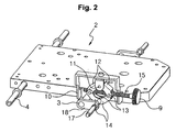
- a heavy equipment console box having a conventional height adjustment device includes a base plate 2 mounted on a suspension 1 (in which buffer means is installed) fixed to an inner bottom surface of a cab, and left and right console boxes 7 and 8 mounted on both end parts of a driving shaft 3 and a hinge shaft 4 provided in front and rear of the base plate 2 to rotate about the hinge shaft 4 when a control handle 9 connected to the driving shaft 3 rotates.
- control levers 5 and 6 for controlling a working device such as a boom, an arm, or the like, in accordance with a manipulation signal corresponding to the amount of manipulation by an operator, are installed, respectively.
- the height adjustment device for the console box includes a bracket 10 fixed to one side surface of the base plate 2, a pair of upper arms 12 having upper ends rotatably connected to an upper pin 11 fixed to the bracket 10, a pair of lower arms 14 having upper ends rotatably connected to a pair of adjustment pins 13 fixed to lower ends of the upper arms 12, a control handle 9 having a handle shaft 15 screw-engaged with one of the pair of adjustment pins 13 and passing through the other of the pair of adjustment pins 13 to link the upper arms 12 and the lower arms 14, and a rotary arm 18 having both ends fixed to a lower pin 17 and the driving shaft 3 fixed to lower ends of the lower arms 14 to transfer a rotating force of the control handle 9 to the driving shaft 3.
- the upper arms 12 and the lower arms 14 move in left and right directions along the handle shaft 15 in accordance with the rotating direction of the control handle 9, and thus the rotary arm 18 connected to the lower pin 17 is rotated clockwise or counterclockwise, as shown in the drawing.
- an operator adjusts the height of the console box 8 so that the operator can keep an optimal operating posture in accordance with the operating habits and the body shape of the operator.
- the present invention has been made to solve the above-mentioned problems occurring in the prior art while advantages achieved by the prior art are maintained intact.
- One object of the present invention is to provide a height adjustment device for a heavy equipment console box having weight balancing, which can provide convenience to a user by minimizing load acting on a driving shaft of a console box due to the self-load of the console box, and thus making it possible to rotate the driving shaft even with a small manipulation force.
- Another object of the present invention is to provide a height adjustment device for a heavy equipment console box having weight balancing, which can heighten the reliability of the equipment by keeping a uniform manipulation force acting on a control handle for rotating a driving shaft of the console box in order to adjust the height of a control lever of the console box.
- a height adjustment device for a heavy equipment console box having weight balancing which includes a suspension mounted on an inner bottom surface of a cab; a lower member mounted on the suspension; an upper member slidably mounted on the lower member in forward and backward directions of the equipment; a buffer means having one end fixed to the lower member and the other end fixed to the upper member to attenuate impact and vibration generated in the forward and backward directions of the equipment by relative movement of the upper member to the lower member; a height adjustment means including a frame mounted on the upper member, a hinge shaft fixed to the frame and having both ends fixed to rear parts of console boxes, a driving shaft rotatably fixed to the frame and having both ends fixed to front parts of the console boxes, and a control handle connected to the driving shaft to adjust the height of the console boxes in accordance with its rotating direction; a locking means for locking and unlocking forward and backward movement of the upper member against the lower member when a pusher installed on one side of
- the height adjustment means may include a rotary shaft rotatably mounted on a bracket fixed in front of one side surface of the frame, and having one end fixed to the control handle and the other end provided with a screw part formed thereon; a union having a screw hole penetratedly formed in the center thereof to be screw-engaged with the screw part, and converting rotational movement of the rotary shaft into rectilineal movement; and a power transfer member having one end rotatably fixed to the union and the other end rotatably fixed to the bracket mounted on an outer surface of the driving shaft; wherein when the control handle is rotated, the union for converting the rotational movement of the rotary shaft into the rectilineal movement pushes or pulls the power transfer member, and thus the driving shaft is rotated about the hinge shaft to adjust the height of the console boxes.
- the locking means include locking grooves penetratedly formed on specified positions of a bottom surface of the lower member; lockers rotatably fixed to the upper member and having engagement pieces formed on bottom surfaces thereof to be engaged with the locking grooves, respectively, the locking means including a first locker 72 having a fixing piece formed on an upper surface thereof to project to an upper part of the upper member and a second locker rotatably connected to the first locker; an elastic member for elastically supporting the first locker so that the engagement pieces are locked into the locking grooves; and a cable having one end fixed to a bottom surface of the pusher and the other end fixed to a fixing piece, the cable locking and unlocking the forward and backward movement of the upper member against the lower member by locking and unlocking the engagement pieces into and from the locking grooves in accordance with the manipulation of the pusher.
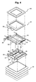
- a height adjustment device for a heavy equipment console box having weight balancing includes a suspension 50 mounted on an inner bottom surface of a cab; a lower member 51 mounted on the suspension 50; an upper member 52 slidably mounted on the lower member 51 in forward and backward directions of the equipment; a buffer means having one end fixed to the lower member 51 and the other end fixed to the upper member 52 to attenuate impact and vibration generated in the forward and backward directions of the equipment by relative movement of the upper member 52 to the lower member 51; a height adjustment means including a frame 53 mounted on the upper member 52, a hinge shaft 56 fixed to the frame 53 and having both ends fixed to rear parts of console boxes 54 and 55, a driving shaft 57 rotatably fixed to the frame 53 and having both ends fixed to front parts of the console boxes 54 and 55, and a control handle 58 connected to the driving shaft 57 to adjust the height of the console boxes 54 and 55 in accordance with its rotating direction; a locking means for
- the height adjustment means includes a rotary shaft 64 rotatably mounted on a bracket 63 fixed in front of one side surface of the frame 53, and having one end fixed to the control handle 58 and the other end provided with a screw part 65 formed thereon; a union 66 having a screw hole penetratedly formed in the center thereof to be screw-engaged with the screw part 65, and converting rotational movement of the rotary shaft 64 into rectilineal movement; and a power transfer member 68 having one end rotatably fixed to the union 66 and the other end rotatably fixed to the bracket 67 mounted on an outer surface of the driving shaft 57.
- the locking means includes locking grooves 69 penetratedly formed on specified positions of a bottom surface of the lower member 51; lockers rotatably fixed to the upper member 52 by engagement pins 76 engaged with engagement grooves 75 formed on the upper member 52, and having engagement pieces 70 formed to project from the bottom surfaces thereof to be locked into and unlocked from the locking grooves 69, respectively, the locking means including a first locker 72 having a fixing piece 71 formed on an upper surface thereof to project to an upper part of the upper member 52 and an engagement pin 77 formed on one side surface thereof, and a second locker 73 having engagement grooves 78 formed on one side surface thereof to be engaged with the engagement pin 77 so that the second locker 73 is rotatably connected to the first locker 72; an elastic member 74 (e.g., a compression coil spring installed between the upper member 52 and an upper surface of the first locker 72) for elastically supporting the first locker 72 so that the engagement pieces 70 are locked into the locking grooves 69; and a cable 79 having one end fixed to a bottom surface of the
- the engagement pieces 70 are locked into and unlocked from the locking grooves 69 by the cable 79, and thus the forward and backward movement of the upper member 52 with respect to the lower member 51 can be locked and unlocked.
- the buffer means includes a first elastic member 86 having one end fixed to a first fixing bar 84 formed on the rear of the upper member 52 and the other end fixed to a fixing piece 85 formed in the center position of the lower member 51; a second elastic member 88 having one end fixed to the fixing piece 85 of the lower member 51 and the other end fixed to a second fixing bar 87 formed in front of the upper member 52, the second elastic member 88 being arranged in the same line as the first elastic member 86; and a damper 89 having a head part fixed to the rear of the upper member 52 and a rod part fixed to a fixing piece (not illustrated) formed in front of the lower member 51, the damper 89 being arranged opposite to the first and second elastic members 86 and 88.
- the first and second elastic members 86 and 88 and the damper 89 are installed to apply a tension force and a buffering force in forward and backward directions of the equipment (i.e., the X-axis direction in which the equipment travels).
- the reference numeral 91 denotes a plate having one front side on which the pusher 59 is rotatably installed, and mounted on the frame 53
- the reference numeral 100 denotes a plate mounted on the frame 53 and on which a seat is detachably placed.
- the constructions such as the suspension 50 installed on the inner bottom surface of the cab, the console boxes 54 and 55 for controlling the working device such as a boom in accordance with the amount of manipulation of the control levers 60 and 61, and the like, are substantially the same as those as illustrated in FIG. 1 , and thus the detailed description of their construction and operation will be omitted.
- rollers 80 and 81 installed on left and right sides of the upper member 52 can slide in forward and backward directions of the equipment in a specified section along guide rails 82 and 83 formed on left and right sides of the lower member 51.
- the relative movement of the upper member 52 to the lower member 51 becomes possible due to the tension force acting in the forward and backward directions through the first and second elastic members 86 and 88.
- the relative movement of the upper member 52 to the lower member 51 becomes possible due to the buffer force acting in the forward and backward directions through the damper 89.
- the operator adjusts the height of the console boxes 54 and 55 so that the operator can keep an optimal operating posture in accordance with the operating habits and the body shape of the operator.
- the driving shaft 57 rotatably fixed to the front of the left and right console boxes 54 and 55 is rotated clockwise, as shown in the drawing, and thus the console boxes 54 and 55 are lifted up to the operator.
- the user can manipulate the control levers 60 and 61 of the console boxes 54 and 55 mounted on left and right sides of the cab on the optimal operating posture required in accordance with the body shape of the operator. Accordingly, the operator's fatigue is reduced, and thus the operator can work in an agreeable working environment.
- the control handle 58 is manipulated by a small manipulation force to adjust the height of the console boxes 54 and 55.
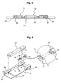
- the elastic member 62 e.g., tension coil spring
- P(LH) means a rotating force acting on a lever 57a formed at the right end of the driving shaft 57 to rotate the right console box 55
- P(RH) means a rotating force acting on a lever 57b formed at the left end of the driving shaft 57 to rotate the left console box 54
- L 1 is a vertical distance between the center axis of the driving shaft 57 and the center axis of the levers 57a and 57b
- L 2 is a vertical distance between the center axis of the driving shaft 57 and the center point on which the tension force of the elastic member 62 acts
- P(SPRING) is the tension force acting on the elastic member 62.
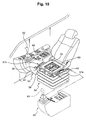
- a height adjustment device for a heavy equipment console box having weight balancing includes a suspension 50 mounted on an inner bottom surface of a cab; a frame 53 mounted on the suspension 50; a height adjustment means including a hinge shaft 56 fixed to the frame 53 and having both ends fixed to rear parts of console boxes 54 and 55, a driving shaft 57 rotatably fixed to the frame 53 and having both ends fixed to front parts of the console boxes 54 and 55, and a control handle 58 connected to the driving shaft 57 to adjust the height of the console boxes 54 and 55 in accordance with its rotating direction; and an elastic member 62 (e.g., a tension coil spring) having one end fixed to one side surface of the frame 53 and the other hand fixed to an outer surface of the driving shaft 57, the elastic member 62 having a specified tension force so that a manipulation force of the control handles 58 for rotating the driving shaft 57 becomes zero when control levers 60 and 61 installed on the console boxes 60 and 61 are set to a
- a hinge shaft 56 fixed to the frame 53 and having both
- the height adjustment means and the elastic member 62 are substantially the same as those according to an embodiment of the present invention, and thus the detailed description thereof will be omitted.
- the same drawing reference numerals are used for the same elements across various figures.
- the height adjustment means of the console boxes 54 and 55 is installed on one side surface of the frame 53, and both end parts of the elastic member 62 (e.g., tension coil spring) are installed on the other surface of the frame 53 and the outer surface of the driving shaft 57, respectively.
- the elastic member 62 e.g., tension coil spring
- the number of corresponding components is reduced in comparison to the height adjustment device for a heavy equipment console box having weight balancing according to an embodiment of the present invention, and thus the manufacturing cost can be reduced.
- the height adjustment device for heavy equipment console box having weight balancing has the following advantages.
- the load acting on the driving shafts of the console boxes due to the self-load of the console boxes installed on left and right sides of the cab can be minimized, and thus the height of the console boxes can be adjusted by rotating the driving shaft even with a small manipulation force.
Landscapes
- Engineering & Computer Science (AREA)
- Aviation & Aerospace Engineering (AREA)
- Transportation (AREA)
- Mechanical Engineering (AREA)
- Mining & Mineral Resources (AREA)
- Civil Engineering (AREA)
- General Engineering & Computer Science (AREA)
- Structural Engineering (AREA)
- Component Parts Of Construction Machinery (AREA)
- Mechanical Control Devices (AREA)
- Vehicle Step Arrangements And Article Storage (AREA)
Claims (2)
- Dispositif de réglage de hauteur pour boîte de console d'équipement lourd (54, 55) présentant un équilibrage de poids, comprenant:une suspension (50) montée sur une surface inférieure intérieure d'une cabine;un élément inférieur (51) monté sur la suspension ;un élément supérieur (52) monté de manière coulissante sur l'élément inférieur (51) dans les directions avant et vers l'arrière de l'équipement;un moyen tampon ayant une extrémité fixée à l'élément inférieur (51) et l'autre extrémité fixée à l'élément supérieur (52) pour atténuer les impacts et les vibrations générés dans les directions avant et arrière de l'équipement par le mouvement relatif de l'élément supérieur (52) par rapport à l'élément inférieur (51);un moyen de réglage de hauteur comportant un cadre (53) monté sur l'élément supérieur (52), un arbre à charnière (56) fixé au cadre (53) et dont les deux extrémités sont fixées aux parties arrière des boîtes de console (54, 55), un arbre d'entraînement (57) fixé en rotation au cadre (53) et dont les deux extrémités sont fixées aux parties avant des boîtes de console (54, 55), et une poignée de commande (58) connecté à l'arbre d'entraînement (57) pour ajuster la hauteur des boîtes de console (54, 55) en fonction de son direction de rotation;un moyen de verrouillage permettant de verrouiller et de déverrouiller le mouvement avant et arrière de l'élément supérieur (52) contre l'élément inférieur (51) en cas de manipulation d'un poussoir (59) installé d'un côté du cadre (53); etun élément élastique (62) ayant une extrémité fixée à une surface latérale du cadre (53) et l'autre extrémité fixée à une surface externe de l'arbre d'entraînement (57), l'élément élastique (62) ayant une force de tension spécifique pour qu'une force de manipulation de la poignée de commande (58) permettant de faire tourner l'arbre d'entraînement (57) soit nulle lorsque des leviers de commande des boîtes de console (54, 55) sont réglés à une hauteur spécifique;où le moyen de verrouillage comprend des rainures de verrouillage (69) pénétrant dans des positions spécifiques d'une surface inférieure de l'élément inférieur (51);des verrous fixés en rotation à l'élément supérieur (52) et ayant des pièces d'embrayage (70) constituées sur des surfaces inférieures de celui-ci pour embrayer les rainures de verrouillage (69), respectivement, le moyen de verrouillage comportant un premier verrou (72) ayant une pièce de fixation (71) formée sur une surface supérieure de celui-ci pour faire saillie vers une partie supérieure de l'élément supérieur (52) et un second verrou (73) connecté en rotation au premier verrou (72),un élément élastique (74) pour soutenir élastiquement le premier verrou (72) pour verrouiller les pièces d'embrayage (70) dans les rainures de verrouillage (69), etun câble (79) ayant une extrémité fixée à une surface inférieure du poussoir (59), et l'autre extrémité fixée à une pièce de fixation, le câble (79) permettant de verrouiller et de déverrouiller le mouvement avant et arrière de l'élément supérieur (52) contre l'élément inférieur (51) en verrouillant et déverrouillant les pièces d'embrayage (70) dans les rainures de verrouillage (69) selon la manipulation du poussoir.
- Dispositif de réglage de hauteur selon la revendication 1, où le moyen de réglage de hauteur comprend :un arbre de rotation (64) monté en rotation sur un support (67) fixé devant une surface latérale du cadre (53), et ayant une extrémité fixée à la poignée de commande (58) et l'autre extrémité munie d'une partie vissage (65) formée sur celle-ci;un raccord (66) présentant un trou de vis pénétrant au centre de celui-ci pour se visser dans la partie vissage (65), et conversion du mouvement de rotation de l'arbre rotatif (64) en mouvement rectiligne; etun élément de transfert de force (68) ayant une extrémité fixée en rotation au raccord (66) et l'autre extrémité fixée en rotation au support (67) monté sur une surface externe de l'arbre d'entraînement (57);où lorsque l'on fait tourner la poignée de commande (58), le raccord (66) permettant la conversion du mouvement de rotation de l'arbre rotatif (64) en mouvement rectiligne pousse ou tire l'élément de transfert de force (68), et ainsi l'arbre d'entraînement (57) est mis en rotation autour de l'arbre à charnière (56) pour ajuster la hauteur des boîtes de console (54, 55).
Applications Claiming Priority (1)
| Application Number | Priority Date | Filing Date | Title |
|---|---|---|---|
| KR1020070036995A KR100910168B1 (ko) | 2007-04-16 | 2007-04-16 | 웨이트 밸런싱을 갖는 높낮이 조절장치가 구비된 중장비용콘솔박스 |
Publications (3)
| Publication Number | Publication Date |
|---|---|
| EP1982865A2 EP1982865A2 (fr) | 2008-10-22 |
| EP1982865A3 EP1982865A3 (fr) | 2009-10-21 |
| EP1982865B1 true EP1982865B1 (fr) | 2012-02-29 |
Family
ID=39671908
Family Applications (1)
| Application Number | Title | Priority Date | Filing Date |
|---|---|---|---|
| EP08007088A Ceased EP1982865B1 (fr) | 2007-04-16 | 2008-04-10 | Dispositif de réglage de hauteur pour boîte de console d'équipement lourd disposant d'un équilibrage de poids |
Country Status (5)
| Country | Link |
|---|---|
| US (1) | US20080252127A1 (fr) |
| EP (1) | EP1982865B1 (fr) |
| JP (1) | JP5237676B2 (fr) |
| KR (1) | KR100910168B1 (fr) |
| CN (1) | CN101289157B (fr) |
Families Citing this family (8)
| Publication number | Priority date | Publication date | Assignee | Title |
|---|---|---|---|---|
| KR101547857B1 (ko) * | 2013-04-01 | 2015-08-27 | 임국건 | 작업용 차량의 레버스탠드 조절장치 |
| FR3044273B1 (fr) * | 2015-11-30 | 2018-01-05 | Faurecia Interieur Industrie | Console coulissante, gamme de consoles, procede de production correspondant |
| CN106004555A (zh) * | 2016-06-18 | 2016-10-12 | 金余和 | 一种双向提篮式安全座椅底座总成 |
| US10253477B2 (en) | 2016-10-21 | 2019-04-09 | Komatsu Ltd. | Work vehicle |
| JP6606117B2 (ja) * | 2017-03-29 | 2019-11-13 | 日立建機株式会社 | 建設機械の操作レバー装置 |
| DE102017129556B4 (de) * | 2017-12-12 | 2023-03-09 | Grammer Aktiengesellschaft | Fahrzeugsitz mit Verstelleinrichtung |
| EP3663128B1 (fr) * | 2018-12-06 | 2023-10-04 | Kubota Corporation | Véhicule de travail |
| CN112429670B (zh) * | 2020-11-24 | 2021-07-09 | 为康(苏州)基因科技有限公司 | 一种基因检测设备移动箱 |
Family Cites Families (24)
| Publication number | Priority date | Publication date | Assignee | Title |
|---|---|---|---|---|
| US2429017A (en) * | 1943-06-14 | 1947-10-14 | Rose John P De | Adjustable seat support |
| US3853298A (en) * | 1973-06-11 | 1974-12-10 | Gen Motors Corp | Energy absorbing seat adjuster |
| US4125242A (en) * | 1974-09-28 | 1978-11-14 | Messrs. Willibald Grammer | Spring mounted seat with height adjustment |
| FR2374186A1 (fr) * | 1976-12-17 | 1978-07-13 | Keiper Automobiltechnik Gmbh | Siege pour vehicules, en particulier pour vehicules automobiles |
| US4344597A (en) * | 1980-04-21 | 1982-08-17 | Milsco Manufacturing Company | Vehicle seat with fore-and-aft shock isolation |
| JPS59102658U (ja) * | 1982-12-25 | 1984-07-10 | 三菱農機株式会社 | 作業車輛におけるシ−ト装置 |
| US4607884A (en) * | 1984-08-06 | 1986-08-26 | Chrysler Corporation | Vehicle easy entry seat latching mechanism |
| US4611783A (en) * | 1985-01-04 | 1986-09-16 | Tachikawa Spring Co., Ltd. | Body-weight adjusting device of a seat suspension |
| JPS6282828U (fr) * | 1985-11-14 | 1987-05-27 | ||
| JPH0755506Y2 (ja) * | 1988-05-20 | 1995-12-20 | パイオニア株式会社 | 基板回路検査装置 |
| US5011109A (en) * | 1989-03-18 | 1991-04-30 | Tachi-S Co., Ltd. | Suspension device for seat |
| JPH06228987A (ja) * | 1993-02-03 | 1994-08-16 | Shin Caterpillar Mitsubishi Ltd | 作業機における回動式操作レバー装置 |
| US5364060A (en) * | 1993-03-19 | 1994-11-15 | Milsco Manufacturing Company | Adjustable mechanized seat suspension |
| JPH0790882A (ja) * | 1993-09-27 | 1995-04-04 | Hitachi Constr Mach Co Ltd | 建設機械の操作スタンド装置 |
| JP3757320B2 (ja) * | 1995-07-19 | 2006-03-22 | カイペル・ゲゼルシヤフト・ミツト・ベシユレンクテル ハフツング・ウント・コンパニ− | 自動車の座席を長手方向に調節する装置 |
| JPH09302726A (ja) * | 1996-05-11 | 1997-11-25 | Yutani Heavy Ind Ltd | 建設機械の操縦装置 |
| CN2299762Y (zh) * | 1997-06-24 | 1998-12-09 | 上海交运股份有限公司 | 工程机械座椅可调式缓冲装置 |
| US6271657B1 (en) * | 1997-07-25 | 2001-08-07 | Advantest Corporation | Test head positioner for semiconductor device testing apparatus |
| JPH11128277A (ja) | 1997-10-23 | 1999-05-18 | Akira Korosue | レバー操作式車椅子 |
| DE19841200C2 (de) * | 1998-09-09 | 2002-01-31 | Siemens Ag | Gewichtsausgleichseinrichtung für eine verstellbare Untersuchungseinrichtung eines medizinischen Gerätes |
| KR100430399B1 (ko) * | 2001-12-18 | 2004-05-04 | 볼보 컨스트럭션 이키프먼트 홀딩 스웨덴 에이비 | 중장비 조종박스의 높낮이 조절장치 |
| JP3696574B2 (ja) * | 2002-05-28 | 2005-09-21 | しげる工業株式会社 | 車両の座席高さ調節装置 |
| JP2005096746A (ja) * | 2003-08-22 | 2005-04-14 | Komatsu Ltd | 作業車両の運転シート支持装置 |
| KR100900434B1 (ko) * | 2007-04-16 | 2009-06-01 | 볼보 컨스트럭션 이키프먼트 홀딩 스웨덴 에이비 | 전후방향의 완충수단이 장착된 중장비용 시이트 |
-
2007
- 2007-04-16 KR KR1020070036995A patent/KR100910168B1/ko not_active Expired - Fee Related
-
2008
- 2008-04-03 US US12/080,481 patent/US20080252127A1/en not_active Abandoned
- 2008-04-10 EP EP08007088A patent/EP1982865B1/fr not_active Ceased
- 2008-04-14 JP JP2008104482A patent/JP5237676B2/ja not_active Expired - Fee Related
- 2008-04-14 CN CN2008100904392A patent/CN101289157B/zh not_active Expired - Fee Related
Also Published As
| Publication number | Publication date |
|---|---|
| CN101289157A (zh) | 2008-10-22 |
| JP5237676B2 (ja) | 2013-07-17 |
| KR100910168B1 (ko) | 2009-07-31 |
| KR20080093276A (ko) | 2008-10-21 |
| US20080252127A1 (en) | 2008-10-16 |
| EP1982865A3 (fr) | 2009-10-21 |
| EP1982865A2 (fr) | 2008-10-22 |
| JP2008267131A (ja) | 2008-11-06 |
| CN101289157B (zh) | 2013-09-11 |
Similar Documents
| Publication | Publication Date | Title |
|---|---|---|
| EP1982864B1 (fr) | Combinaison avec un siège et des boîte de console | |
| EP1982865B1 (fr) | Dispositif de réglage de hauteur pour boîte de console d'équipement lourd disposant d'un équilibrage de poids | |
| EP1350667B1 (fr) | Véhicule industriel | |
| EP3392416B1 (fr) | Dispositif de levier de commande pour machine de construction | |
| US10358069B2 (en) | Armrest assembly for vehicle interior | |
| KR102941561B1 (ko) | 건설 기계 | |
| CA1146459A (fr) | Assise pour siege de conducteur d'un engin de terrassement | |
| US6646891B2 (en) | Apparatus for adjusting a height of control boxes | |
| KR100530030B1 (ko) | 자동차용 틸트 스티어링 장치 | |
| EP4238819B1 (fr) | Agencement d'accoudoir amélioré pour véhicule de travail | |
| JP2025027852A (ja) | リモコンユニット、及び、作業用車両 | |
| JP2020149294A (ja) | 建設機械の遠隔操作装置 | |
| JP2007326469A (ja) | 建設機械の操縦席および建設機械 | |
| CN120134928A (zh) | 一种工程机械操纵箱 | |
| JP5872385B2 (ja) | 車両用シート | |
| CN211795065U (zh) | 用于使至少一个容纳容器运动的组件和家具 | |
| KR20250056813A (ko) | 보행형 작업기 | |
| JP5872386B2 (ja) | 車両用シート | |
| WO2024043003A1 (fr) | Mécanisme de fonctionnement et véhicule de travail | |
| JP2001352802A (ja) | 耕耘ロータリ装置のハンガーロッド支持構造 |
Legal Events
| Date | Code | Title | Description |
|---|---|---|---|
| PUAI | Public reference made under article 153(3) epc to a published international application that has entered the european phase |
Free format text: ORIGINAL CODE: 0009012 |
|
| AK | Designated contracting states |
Kind code of ref document: A2 Designated state(s): AT BE BG CH CY CZ DE DK EE ES FI FR GB GR HR HU IE IS IT LI LT LU LV MC MT NL NO PL PT RO SE SI SK TR |
|
| AX | Request for extension of the european patent |
Extension state: AL BA MK RS |
|
| PUAL | Search report despatched |
Free format text: ORIGINAL CODE: 0009013 |
|
| AK | Designated contracting states |
Kind code of ref document: A3 Designated state(s): AT BE BG CH CY CZ DE DK EE ES FI FR GB GR HR HU IE IS IT LI LT LU LV MC MT NL NO PL PT RO SE SI SK TR |
|
| AX | Request for extension of the european patent |
Extension state: AL BA MK RS |
|
| 17P | Request for examination filed |
Effective date: 20100315 |
|
| 17Q | First examination report despatched |
Effective date: 20100416 |
|
| AKX | Designation fees paid |
Designated state(s): DE FR GB IT |
|
| REG | Reference to a national code |
Ref country code: DE Ref legal event code: R079 Ref document number: 602008013687 Country of ref document: DE Free format text: PREVIOUS MAIN CLASS: B60N0002500000 Ipc: B60N0002460000 |
|
| RIC1 | Information provided on ipc code assigned before grant |
Ipc: B60N 2/46 20060101AFI20110818BHEP |
|
| GRAP | Despatch of communication of intention to grant a patent |
Free format text: ORIGINAL CODE: EPIDOSNIGR1 |
|
| GRAS | Grant fee paid |
Free format text: ORIGINAL CODE: EPIDOSNIGR3 |
|
| GRAA | (expected) grant |
Free format text: ORIGINAL CODE: 0009210 |
|
| AK | Designated contracting states |
Kind code of ref document: B1 Designated state(s): DE FR GB IT |
|
| REG | Reference to a national code |
Ref country code: GB Ref legal event code: FG4D |
|
| REG | Reference to a national code |
Ref country code: DE Ref legal event code: R096 Ref document number: 602008013687 Country of ref document: DE Effective date: 20120503 |
|
| PLBE | No opposition filed within time limit |
Free format text: ORIGINAL CODE: 0009261 |
|
| STAA | Information on the status of an ep patent application or granted ep patent |
Free format text: STATUS: NO OPPOSITION FILED WITHIN TIME LIMIT |
|
| 26N | No opposition filed |
Effective date: 20121130 |
|
| REG | Reference to a national code |
Ref country code: DE Ref legal event code: R097 Ref document number: 602008013687 Country of ref document: DE Effective date: 20121130 |
|
| REG | Reference to a national code |
Ref country code: FR Ref legal event code: PLFP Year of fee payment: 9 |
|
| REG | Reference to a national code |
Ref country code: FR Ref legal event code: PLFP Year of fee payment: 10 |
|
| REG | Reference to a national code |
Ref country code: DE Ref legal event code: R079 Ref document number: 602008013687 Country of ref document: DE Free format text: PREVIOUS MAIN CLASS: B60N0002460000 Ipc: B60N0002750000 |
|
| REG | Reference to a national code |
Ref country code: FR Ref legal event code: PLFP Year of fee payment: 11 |
|
| PGFP | Annual fee paid to national office [announced via postgrant information from national office to epo] |
Ref country code: IT Payment date: 20230421 Year of fee payment: 16 Ref country code: FR Payment date: 20230421 Year of fee payment: 16 Ref country code: DE Payment date: 20230427 Year of fee payment: 16 |
|
| REG | Reference to a national code |
Ref country code: DE Ref legal event code: R081 Ref document number: 602008013687 Country of ref document: DE Owner name: VOLVO CONSTRUCTION EQUIPMENT AB, SE Free format text: FORMER OWNER: VOLVO CONSTRUCTION EQUIPMENT HOLDING SWEDEN AB, ESKILSTUNA, SE |
|
| PGFP | Annual fee paid to national office [announced via postgrant information from national office to epo] |
Ref country code: GB Payment date: 20230418 Year of fee payment: 16 |
|
| REG | Reference to a national code |
Ref country code: DE Ref legal event code: R119 Ref document number: 602008013687 Country of ref document: DE |
|
| GBPC | Gb: european patent ceased through non-payment of renewal fee |
Effective date: 20240410 |
|
| PG25 | Lapsed in a contracting state [announced via postgrant information from national office to epo] |
Ref country code: DE Free format text: LAPSE BECAUSE OF NON-PAYMENT OF DUE FEES Effective date: 20241105 |
|
| PG25 | Lapsed in a contracting state [announced via postgrant information from national office to epo] |
Ref country code: GB Free format text: LAPSE BECAUSE OF NON-PAYMENT OF DUE FEES Effective date: 20240410 |
|
| PG25 | Lapsed in a contracting state [announced via postgrant information from national office to epo] |
Ref country code: FR Free format text: LAPSE BECAUSE OF NON-PAYMENT OF DUE FEES Effective date: 20240430 |
|
| PG25 | Lapsed in a contracting state [announced via postgrant information from national office to epo] |
Ref country code: GB Free format text: LAPSE BECAUSE OF NON-PAYMENT OF DUE FEES Effective date: 20240410 Ref country code: FR Free format text: LAPSE BECAUSE OF NON-PAYMENT OF DUE FEES Effective date: 20240430 Ref country code: DE Free format text: LAPSE BECAUSE OF NON-PAYMENT OF DUE FEES Effective date: 20241105 |
|
| PG25 | Lapsed in a contracting state [announced via postgrant information from national office to epo] |
Ref country code: IT Free format text: LAPSE BECAUSE OF NON-PAYMENT OF DUE FEES Effective date: 20240410 |