EP1983149B1 - Mât - Google Patents
Mât Download PDFInfo
- Publication number
- EP1983149B1 EP1983149B1 EP08007129.3A EP08007129A EP1983149B1 EP 1983149 B1 EP1983149 B1 EP 1983149B1 EP 08007129 A EP08007129 A EP 08007129A EP 1983149 B1 EP1983149 B1 EP 1983149B1
- Authority
- EP
- European Patent Office
- Prior art keywords
- carriage
- leader
- work unit
- feed
- accordance
- Prior art date
- Legal status (The legal status is an assumption and is not a legal conclusion. Google has not performed a legal analysis and makes no representation as to the accuracy of the status listed.)
- Active
Links
Images


Classifications
-
- E—FIXED CONSTRUCTIONS
- E21—EARTH OR ROCK DRILLING; MINING
- E21B—EARTH OR ROCK DRILLING; OBTAINING OIL, GAS, WATER, SOLUBLE OR MELTABLE MATERIALS OR A SLURRY OF MINERALS FROM WELLS
- E21B7/00—Special methods or apparatus for drilling
- E21B7/02—Drilling rigs characterised by means for land transport with their own drive, e.g. skid mounting or wheel mounting
Definitions
- the present invention relates to a broker with a feed slide, which is displaceable in a longitudinal direction at the broker, and a tool carriage, which is detachably connectable to the feed slide for mounting and dismounting of the implement.
- implement slides are generally mounted with four bolts on the feed slide over lateral bolt receptacles. The bolts are inserted during assembly, after the receiving bushes of both carriages have been positioned exactly above each other. Thus, the insertion of the bolt without much effort is possible, it requires a very accurate alignment of the leader with the attached feed carriage on the standing on the ground implement sled. The assembly of the implement sled on the feed slide is therefore complicated, complicated and time consuming.
- the object of the present invention is therefore to provide a broker, in which the implement sled can be mounted on the feed slide easier and faster.
- first connecting elements are provided which, by means of a relative movement of the implement slide and the feed slide, establish a first connection of working device slides and feed slides via which the implement slide is seated on the feed slide.
- the first fasteners on implement slides and feed slide are positioned so that they can be pushed together in the direction in which they make the first connection via the relative movement between implement slides and feed slide.
- the further positioning is then already supported by the first connecting elements.
- the first connection is effected by a relative movement of implement slide and feed slide in the longitudinal direction of the leader, and in particular advantageously takes place at a substantially vertical orientation of the leader, the movement of the feed carriage relative to the implement slide from bottom to top.
- the implement slide sits on top of the feed slide and is then held in this position by the first connecting elements.
- the first connection allows a certain movement of the implement slide relative to the feed slide in the longitudinal direction of the leader.
- this allows for a load of the implement sled by the implement a relative movement of the first connecting elements against each other, so that the carriage can be held here alone via a second connection, allowing a targeted application of force.
- the first connecting elements allow the movement of the feed carriage relative to the implement slide from bottom to top until the implement slide rests on the feed slide.
- the implement sled is fixed by the first connecting elements in the vertical direction downwards, so that it may only be aligned horizontally with respect to further connecting elements. In this position, the implement slide is still set downwards relative to the feed slide, but still upwardly movable.
- the first connecting elements attach the implement slide on the feed carriage in a mounting position transversely to the longitudinal direction of the leader. If the broker is vertically aligned for mounting, the first fasteners prevent movement of the implement carriage away from the feed carriage after placement of the implement carriage on the feed carriage.
- the first connecting elements in this case form an axis of rotation, so that the implement slide can be folded up on the feed slide.
- implement slides and feed carriages have, in addition to the first connection elements, via which the first connection takes place, second connection elements for producing a second connection. So the implement sled has been placed over the first fasteners on the feed slide and optionally in his Positioning position, it can be connected via the second connecting elements finally with the feed slide.
- this gives rise to the possibility of first pushing the implement slide on the feed carriage via the first connecting elements, and only to align in a mounting position so that the second fasteners can be set.
- first connecting elements are arranged in a vertical orientation of the leader above the second connecting elements.
- the second connecting elements the implement slides on the feed carriage at least in the longitudinal direction of the leader.
- This is the direction in which the z. B. forces must be transferred from the implement slide on the broker, so that the second connecting elements take over this power transmission.
- the first connecting elements allow movement of the implement sled in this direction, this has the advantage that the implement sled in the longitudinal direction of the leader is no longer stored overdetermined. As a result, the power transmission from the implement to the leader can be defined exactly and there are no additional burdens due to internal tension.
- the second connecting elements set the implement slide on the feed carriage in the longitudinal and transverse directions of the leader.
- the implement slide can first be placed on the feed slide in an angled position relative to the feed slide by the first connection elements, whereupon the feed slide and implement slide can be pivoted towards one another.
- the first connecting elements are arranged in the upper region of the implement slides and feed slide, the implement slide is automatically held in position by gravity. In particular, this is advantageous if the second connecting elements are located below the first connecting elements.
- the second connecting elements are in their mounting position after pivoting.
- To mount the implement slide thus initially only the first fasteners must be aligned with each other and pushed into each other, after which the feed slide can be pivoted to the implement slide, causing the second fasteners are already in mounting position, so that this connection can be easily made without further alignment.
- the broker according to the invention comprises a stop for the attached to the feed carriage implement slide, which is particularly designed so that the second connecting elements are in their mounting position when the implement slide abuts the stop.
- This stop which is advantageously arranged on the feed slide, thus allowing the exact positioning of the second connecting elements in their mounting position.
- the stop for the attached to the feed carriage implement slide and / or its counter element is adjustable. This can be done by adjusting the stop or the counter element, the fine adjustment for positioning the second connecting elements.
- the first and / or the second connecting elements are arranged laterally on the implement slide and on the feed slide.
- the feed carriage is facing the broker with his back and surrounds with rear side, laterally arranged guide elements a guide on the broker, over which it is guided along the longitudinal direction of the leader on this.
- the front side of the feed carriage represents a coupling plane to the implement slide.
- first and / or the second connection each comprise two connection points.
- these can each be arranged so that they form a rotation axis.
- the connecting elements are advantageously arranged, as in the prior art, respectively on the right and left sides on the two sides of the tool carriage and feed slide. This results in a secure and easy to install connection.
- the second connecting elements on the left or right of the carriage arranged connection points of mutually associated conventional bolt receptacles in the form of sockets comprise, which are each connected by a bolt.
- first and / or the second connecting elements each have two bolts, which are arranged on the left and right of the implement slide or the feed slide so that the bolts are aligned coaxially to each other.
- the pairs of bolts of the first and the second connecting elements define a common axis of rotation.
- the first connecting elements it should be noted, however, that their bolt pair is supported either on the implement slide or on the feed slide in a conventional bush, while the bolt receptacle on the respective other slide enables the connection to be established by a relative movement of the slide relative to one another.
- the first connecting elements comprise a bolt receptacle, which is open to one side along the longitudinal direction of the leader.
- a bolt can be pushed into the bolt receptacle by moving the feed carriage relative to the implement slide in the longitudinal direction of the leader.
- the bolt receptacle is open transversely to the main direction of the bolt to one side, so that the bolt can be inserted transversely to its main direction in the bolt receptacle.
- the bolt receptacle is open in the longitudinal direction of the leader. If the leader is positioned vertically, this means that the bolt receptacle is open either upwards or downwards, so that the bolt either from below or can be pushed into it from above, while the main direction of the bolt is aligned horizontally.
- the bolt receptacle has an opening which enlarges towards its open side, which facilitates the insertion of the bolt from this side.
- the funnel-like opening guides the bolt.
- the bolt holder is arranged on the feed slide and open at the top.
- the bolt is thus attached in particular horizontally via a conventional receiving socket on the implement slide and is inserted from above into the bolt holder on the feed slide.
- the implement slide thus hangs by the bolts on the feed slide and is held by the resting in the upwardly open bolt receptacle bolts.
- the bolt receptacle is arranged on the implement slide and open at the bottom.
- the bolts are thus mounted horizontally on the feed slide in normal receiving bushes, wherein the downwardly open bolt receptacle can be hung on the implement slide to the bolts.
- the second connecting elements on two receiving sockets which are bolted together.
- the second connection through the second connecting elements is thus carried out as in the prior art, but no more positioning problems arise by the pre-positioning by the first connecting elements, but the bolts can be easily set.
- a multi-coupling in turn facilitates the coupling of the implement to the leader, the multi-coupling advantageously includes all hydraulic and / or electrical connection lines for the implement.
- the present invention also includes the corresponding feed slide or tool slide, via which the simplified assembly according to the invention is possible.
- the present invention comprises a leader slide carriage having top and bottom links for connection to a tool carriage, the top links comprising upwardly open bolt receivers.
- the implement slide can thus have the usual receiving bushes for the bolt and is mounted with already mounted bolts on the feed slide, the bolts engage in the upwardly open bolt receptacles.
- the bolt receivers are arranged laterally.
- the bolt receptacles have an opening which enlarges upwards, which facilitates the insertion of the corresponding bolt on the tool carriage.
- tool carriage and feed slide only need to be positioned approximately against each other because the bolt on the implement slide automatically z. B. slides in a lifting of the feed carriage in the bolt holder.
- the bolt receptacles which are open towards one side can also be arranged on the tool carriage.
- the present invention therefore further comprises a tackler implement sled having upper and lower links for connection to a feed slide, the upper links comprising downwardly open stud receivers.
- the bolts attached to the feed slide can be inserted from below into the downwardly open bolt receptacles.
- the bolt receptacles are advantageously arranged laterally.
- the bolt receptacles have a downwardly enlarging opening, which facilitates the insertion of the corresponding bolt on the feed slide.
- the present invention includes a leader with a tool carriage or feed slide as described above. Obviously, this results in the same advantages as described above.
- the present invention includes a work implement with a tool carriage as described above.
- the tool carriage according to the invention has the advantage that it can be used on existing Gurknd with conventional feed slide, while the feed carriage according to the invention has the advantage that it can be used with the already known implement slides on existing implements.
- the present invention further includes a method of assembling a tool carriage on the advancing carriage of a leader, comprising the steps of: positioning first links on the implement carriage and on the carriage to face each other; Moving the feed carriage relative to the implement slide by the Gurklerkinematik until the implement slide is seated by the first connecting elements on the feed slide.
- the leader is first tilted forward, so that the first connecting elements can be pushed into each other, without the implement sled the feed slide could get in the way.
- the feed slide is moved upwards relative to the implement slide by the leader mechanism.
- So z. B. bolts are pushed into a downwardly open receptacle or vice versa an upwardly open receptacle are pushed from below onto bolts.
- a particularly simple assembly is possible, wherein the bolts are advantageously guided by a correspondingly wider opening.
- implement slides and feed slide are positioned relative to each other in a mounting position after placing the implement sled.
- this positioning is performed by the first connection, for example by forming an axis of rotation about which feed slide and implement slides can be pivoted to each other.
- implement slides and feed slide are connected in the mounting position by second connecting elements.
- the second connecting elements thus provide a secure connection between implement slides and feed slide, without the need for a complex and time-consuming positioning would be necessary.
- FIG. 1 shows an embodiment of the invention
- Gurklers 2 which is hinged to a movable construction equipment 1, in this case a crawler crane.
- the broker 2 can in this case be moved via different adjusting members, wherein it is shown here in a vertical position.
- the broker 2 has laterally arranged guides 7, which are encompassed by corresponding guide elements 17 on the feed slide.
- the feed slide is guided by the interaction of guide elements 17 and guide 7 on the broker 2 along the longitudinal axis, wherein it can be moved via a cable feed system.
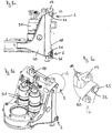
- the implement 30 On feed carriage 10 of the implement slide 20 is mounted, which carries the implement 30. Since the broker 2 is used here for drilling, the implement 30 is a drilling gear. In order to reduce the transport weight and the transport dimensions of the leader 2, often the drilling gear 30 is disassembled together with the Bohrgetriebschlitten 20 for the transport of the feed slide 10 and mounted on site, which is now greatly simplified by the present invention.
- FIGS. 2a to 2c An embodiment of the feed carriage according to the invention, as in the in FIG. 1 shown embodiment of the invention Gurklers is used, is now in detail in FIGS. 2a to 2c shown.
- the feed carriage 10 has the above-mentioned guide elements 17, which surround the guide 7 on the broker 2.
- the guide elements 17 are arranged laterally on the rear side of the feed carriage 10, in each case above and below.
- About the guide elements 17 of the feed carriage is guided on the broker 2 along the longitudinal axis.
- an upper roller 11 and a not to be seen lower roller are provided, which are mounted on axles 13 and 14 and over which the rope of the rope feed system runs.
- the feed slide has upper bolt receivers 15 and lower bolt receivers 16, which are each arranged laterally on the left and right of the feed slide.
- the two upper bolt receivers 15 are in this case with respect to the central longitudinal axis of the feed carriage mirror image opposite, as are the two lower bolt receivers 16.
- the lower bolt receptacle 16 is a receiving socket, as it is already known from the prior art. Here bolts can be inserted along their main direction in the receiving bushes 16 to bolt the feed slide with the implement slide.
- the upper pin receivers 15, however, according to the invention are not listed as jacks, but open at the top. They thus form a trough into which a bolt can be inserted transversely to its main direction from above. The openings of the bolt receptacles 15 are thereby further upward, so that threading the bolt is facilitated.
- the bolt receivers 15 are thus open along the longitudinal direction of the feed slide and thus of the leader 2, so that corresponding bolts on the implement slide can be inserted into the bolt receivers 15 by a relative movement of feed slide to implement slide, so that a first connection is made for pre-positioning ,
- the tool carriage then sits on the bolts in the bolt receptacle 15, so that forms an axis of rotation about which the carriage can be pivoted toward each other.
- the front side 18 of the feed carriage in this case represents a coupling plane, which faces the rear side of a working carriage coupled to the feed carriage.
- FIGS. 3a to 3c now a mounted on the feed slide 10 working carriage 20 is shown, which carries the auger drives 31.
- the tool carriage 20 in this case has in its side regions on the back of upper pin receivers 25 and lower pin receivers 26, which are both designed as receiving sockets.
- the inserted into these receiving bushes 25 and 26 bolts 35 and 36 are aligned by the corresponding arrangement of the sockets 25 and 26 with their main direction transverse to the longitudinal direction of the broker so that their main axis in the coupling plane of implement slides and feed slide.
- the two upper bushes 25, which are located in opposite side regions of the implement carriage 20, are, like the two lower bushes 26, aligned coaxially with one another, so that they form a common axis of rotation.
- the bolts 35 are already inserted into the upper pin holders 25 on the implement slide, or remain there during disassembly anyway.
- the feed slide is located at the bottom of the broker, which is tilted slightly forward with its upper part.
- the bolt receptacles 15, which are open at the top can be positioned on the feed carriage 10 under the bolts 35 on the tool carriage 20.
- the two upper bolts 35 can now be threaded into the bolt receivers 15.
- the assembly of the implement carriage 20 on the feed carriage without great positioning effort is possible, the assembly is additionally facilitated by the fact that the hydraulic and / or electrical connections between leader and implement via the multi-coupling 12 can be made in a single operation for all connecting lines.
- the lower pin receivers 16 and 26 on the feed carriage 10 and tool carriage 20 form together with the bolt 36, the second connection, which defines the implement slide relative to the feed slide up and down and forward and backward.
- the implement slide 20 is also set laterally on the feed slide.
Landscapes
- Life Sciences & Earth Sciences (AREA)
- Engineering & Computer Science (AREA)
- Geology (AREA)
- Mining & Mineral Resources (AREA)
- Physics & Mathematics (AREA)
- Environmental & Geological Engineering (AREA)
- Fluid Mechanics (AREA)
- General Life Sciences & Earth Sciences (AREA)
- Geochemistry & Mineralogy (AREA)
- Earth Drilling (AREA)
- Quick-Acting Or Multi-Walled Pipe Joints (AREA)
Claims (31)
- Mât comprenant un chariot d'avance (10) et un chariot à outils (20), qui peut être assemblé de manière amovible au chariot d'avance (10) pour le montage et le démontage de l'outil, des premiers éléments d'assemblage (15, 25, 35) étant prévus, qui établissent, par un mouvement relatif du chariot à outils (20) et du chariot d'avance (10), une première liaison (5) du chariot à outils (20) et du chariot d'avance (10), par le biais de laquelle le chariot à outils (20) repose sur le chariot d'avance (10),
caractérisé en ce que
le chariot d'avance peut être déplacé dans une direction longitudinale sur le mât, en ce que la première liaison (5) se fait par un mouvement relatif du chariot à outils (20) et du chariot d'avance (10) dans la direction longitudinale du mât, et en particulier lors d'une orientation sensiblement verticale du mât, le mouvement du chariot d'avance (10) par rapport au chariot à outils (20) se fait de bas en haut, en ce que le chariot à outils (20) et le chariot d'avance (10) comportent, outre les premiers éléments d'assemblage (15, 25, 35), par le biais desquels la première liaison (5) est effectuée, des seconds éléments d'assemblage (16, 26, 36) destinés à établir une seconde liaison (6), en ce que les premiers éléments d'assemblage (15, 25, 35), lors d'une orientation verticale du mât, sont disposés au-dessus des seconds éléments d'assemblage (16, 26, 36) et en ce que les seconds éléments d'assemblage (16, 26, 36) fixent le chariot à outils (20) sur le chariot d'avance (10) au moins dans la direction longitudinale du mât. - Mât selon la revendication 1, dans lequel
la première liaison (5) permet un certain mouvement du chariot à outils (20) par rapport au chariot d'avance (10) dans la direction longitudinale du mât. - Mât selon l'une des revendications précédentes, dans lequel les premiers éléments d'assemblage (15, 25, 35) fixent le chariot à outils (20) sur le chariot d'avance (10) dans une position de montage transversale à la direction longitudinale du mât.
- Mât selon la revendication 1, dans lequel
les seconds éléments d'assemblage (16, 26, 36) fixent le chariot à outils (20) sur le chariot d'avance (10) dans la direction longitudinale et transversale du mât. - Mât selon l'une des revendications précédentes, dans lequel le chariot à outils (20) peut d'abord être posé sur le chariot d'avance (10) dans une position inclinée par rapport au chariot d'avance (10) par le biais des premiers éléments d'assemblage (15, 25, 35) et le chariot d'avance (10) et le chariot à outils (20) peuvent ensuite être rapprochés l'un contre l'autre par pivotement.
- Mât selon les revendications 1 et 5, dans lequel
les seconds éléments d'assemblage (16, 26, 36) se trouvent dans leur position de montage après le rapprochement par pivotement. - Mât selon l'une des revendications précédentes, dans lequel
une butée est prévue pour le chariot à outils (20) posé sur le chariot d'avance (10), qui est conçue en particulier de telle manière que les seconds éléments d'assemblage (16, 26, 36) se trouvent dans leur position de montage quand le chariot à outils (20) s'appuie contre la butée. - Mât selon la revendication 7, dans lequel
la butée pour le chariot à outils (20) posé sur le chariot d'avance (10) et/ou son contre-élément peuvent être réglés. - Mât selon l'une des revendications précédentes, dans lequel
les premiers et/ou les seconds éléments d'assemblage (16, 26, 36) sont disposés latéralement sur le chariot à outils (20) et sur le chariot d'avance (10). - Mât selon l'une des revendications précédentes, dans lequel
la première et/ou la seconde liaison (6) comprennent respectivement deux points de liaison. - Mât selon l'une des revendications précédentes, dans lequel
les premiers et/ou les seconds éléments d'assemblage (16, 26, 36) comportent respectivement deux boulons (36), qui sont disposés à gauche et à droite du chariot à outils (20) ou du chariot d'avance (10) de telle manière que les boulons (36) sont orientés de manière coaxiale l'un par rapport à l'autre. - Mât selon l'une des revendications précédentes, dans lequel
les premiers éléments d'assemblage (15, 25, 35) comprennent un logement de boulon (15), qui est ouvert vers un côté le long de la direction longitudinale du mât. - Mât selon la revendication 12, dans lequel
le logement de boulon (15) est ouvert vers un côté transversalement à la direction principale du boulon, de telle sorte que le boulon (35) peut être inséré dans le logement de boulon (15) transversalement à sa direction principale. - Mât selon la revendication 12, dans lequel
le logement de boulon (15) comporte une ouverture s'élargissant vers son côté ouvert, qui facilite l'introduction du boulon (35) par ce côté. - Mât selon la revendication 12, dans lequel
le logement de boulon (15) est disposé sur le chariot d'avance (10) et est ouvert vers le haut. - Mât selon la revendication 12, dans lequel
le logement de boulon (15) est disposé sur le chariot à outils (20) et est ouvert vers le bas. - Mât selon la revendication 1, dans lequel
les seconds éléments d'assemblage (16, 26, 36) comprennent deux douilles de réception (16, 26), qui sont boulonnées l'une avec l'autre. - Mât selon l'une des revendications précédentes, dans lequel un raccord multiple (12) est prévu sur le chariot d'avance (10) pour le couplage hydraulique et/ou électrique de l'outil.
- Chariot d'avance pour un mât selon la revendication 1, qui comporte des éléments d'assemblage supérieurs et inférieurs pour la liaison avec un chariot à outils (20),
caractérisé en ce que
les éléments d'assemblage supérieurs (15, 25, 35) comprennent des logements de boulon (15) ouverts vers le haut. - Chariot d'avance selon la revendication 19, dans lequel
les logements de boulon (15) comportent une ouverture s'élargissant vers le haut, qui facilite l'introduction du boulon (35) correspondant sur le chariot à outils (20). - Chariot d'avance selon la revendication 19 ou 20, dans lequel
un raccord multiple (12) est prévu sur le chariot d'avance (10) pour le couplage hydraulique et/ou électrique de l'outil (31). - Chariot à outils pour un mât selon la revendication 1, qui comporte des éléments d'assemblage supérieurs et inférieurs pour la liaison avec un chariot d'avance,
caractérisé en ce que
les éléments d'assemblage supérieurs comprennent des logements de boulon ouverts vers le bas. - Chariot à outils selon la revendication 22, dans lequel
les logements de boulon comportent une ouverture s'élargissant vers le bas, qui facilite l'introduction du boulon correspondant sur le chariot d'avance. - Mât comprenant un chariot d'avance selon les revendications 19 à 21 ou un chariot à outils selon l'une des revendications 22 ou 23.
- Outil comprenant un chariot à outils selon l'une des revendications 22 ou 23.
- Procédé de montage d'un chariot à outils (20) sur le chariot d'avance (10) d'un mât selon la revendication 1, comprenant les étapes consistant à :- positionner des premiers éléments d'assemblage (15, 25, 35) sur le chariot à outils (20) et sur le chariot d'avance (10), de telle sorte qu'ils se font face- déplacer le chariot d'avance (10) par rapport au chariot à outils (20) par le biais de la cinématique du mât, jusqu'à ce que le chariot à outils (20) repose sur le chariot d'avance (10) par le biais des premiers éléments d'assemblage (15, 25, 35).
- Procédé selon la revendication 26, dans lequel
le mât est d'abord incliné vers l'avant. - Procédé selon la revendication 26, dans lequel
le chariot d'avance (10) est déplacé vers le haut par rapport au chariot à outils (20) par le biais de la cinématique du mât. - Procédé selon la revendication 26, dans lequel
le chariot à outils (20) et le chariot d'avance (10) sont positionnés dans une position de montage l'un par rapport à l'autre après la pose du chariot à outils (20). - Procédé selon la revendication 29, dans lequel
le positionnement du chariot à outils (20) par rapport au chariot d'avance (10) dans une position de montage se fait par un redressement du mât auparavant incliné vers l'avant. - Procédé selon la revendication 29, dans lequel
le chariot à outils (20) et le chariot d'avance (10) sont assemblés dans la position de montage par des seconds éléments d'assemblage (16, 26, 36).
Applications Claiming Priority (1)
| Application Number | Priority Date | Filing Date | Title |
|---|---|---|---|
| DE102007017819A DE102007017819A1 (de) | 2007-04-16 | 2007-04-16 | Mäkler |
Publications (4)
| Publication Number | Publication Date |
|---|---|
| EP1983149A2 EP1983149A2 (fr) | 2008-10-22 |
| EP1983149A3 EP1983149A3 (fr) | 2015-01-21 |
| EP1983149B1 true EP1983149B1 (fr) | 2017-05-31 |
| EP1983149B2 EP1983149B2 (fr) | 2024-01-03 |
Family
ID=39523538
Family Applications (1)
| Application Number | Title | Priority Date | Filing Date |
|---|---|---|---|
| EP08007129.3A Active EP1983149B2 (fr) | 2007-04-16 | 2008-04-10 | Mât |
Country Status (2)
| Country | Link |
|---|---|
| EP (1) | EP1983149B2 (fr) |
| DE (1) | DE102007017819A1 (fr) |
Cited By (2)
| Publication number | Priority date | Publication date | Assignee | Title |
|---|---|---|---|---|
| EP3879034A1 (fr) | 2020-03-12 | 2021-09-15 | BAUER Maschinen GmbH | Agencement de chariot pour une machine de construction et procédé associé |
| EP4080012A1 (fr) * | 2021-04-22 | 2022-10-26 | ABI Anlagentechnik-Baumaschinen-Industriebedarf Maschinenfabrik und Vertriebsgesellschaft mbH | Machine de construction pour le génie civil spécial |
Families Citing this family (5)
| Publication number | Priority date | Publication date | Assignee | Title |
|---|---|---|---|---|
| ATE554232T1 (de) * | 2009-02-16 | 2012-05-15 | Bauer Maschinen Gmbh | Mastkopf |
| CN102704839B (zh) * | 2012-06-11 | 2015-05-20 | 重庆迪马工业有限责任公司 | 挂载式一体化液压凿岩钻机 |
| CN103742072A (zh) * | 2013-12-24 | 2014-04-23 | 徐州徐工基础工程机械有限公司 | 一种旋挖钻机可拆卸的组合式扩展鹅头 |
| EP2902582B2 (fr) | 2014-01-29 | 2022-12-28 | BAUER Maschinen GmbH | Système de mât et procédé de fixation d'un outil de travail au rail de coulissage du mât |
| IT201800001088A1 (it) | 2018-01-16 | 2019-07-16 | Soilmec Spa | Assieme per la movimentazione di una attrezzatura di scavo o perforazione del terreno e metodo di attuazione. |
Citations (6)
| Publication number | Priority date | Publication date | Assignee | Title |
|---|---|---|---|---|
| US2080951A (en) | 1934-02-16 | 1937-05-18 | Pfeiffer Paul | Pile driver |
| US3101816A (en) | 1960-05-20 | 1963-08-27 | James A Wood | Drilling and servicing mast |
| DE2254886A1 (de) | 1971-12-13 | 1973-06-20 | Clark Equipment Co | Hubstapler mit abnehmbarer gabel |
| US4208163A (en) | 1978-01-18 | 1980-06-17 | Renholmens Mekaniska Verkstad Ab | Automatic quick-coupling device |
| DE4132314C1 (en) | 1991-09-27 | 1992-12-17 | Ing. G. Klemm, Bohrtechnik Gmbh, 5962 Drolshagen, De | Vehicle mounted piling drill with mast - on which travels carriage with rotary head and tool duct laterally offset w.r.t.carriage guideway |
| DE4312368C2 (de) | 1993-04-16 | 2003-02-06 | Anlagentech Baumasch Ind | Einrichtung zur Befestigung von Arbeitsgeräten am Hubschlitten des Mäklers von Baumaschinen |
Family Cites Families (1)
| Publication number | Priority date | Publication date | Assignee | Title |
|---|---|---|---|---|
| DE2920399C2 (de) † | 1979-05-19 | 1983-05-26 | Carl Kurt Walther Gmbh & Co Kg, 5600 Wuppertal | Multikupplung, insbesondere für Flüssigkeiten |
-
2007
- 2007-04-16 DE DE102007017819A patent/DE102007017819A1/de not_active Withdrawn
-
2008
- 2008-04-10 EP EP08007129.3A patent/EP1983149B2/fr active Active
Patent Citations (6)
| Publication number | Priority date | Publication date | Assignee | Title |
|---|---|---|---|---|
| US2080951A (en) | 1934-02-16 | 1937-05-18 | Pfeiffer Paul | Pile driver |
| US3101816A (en) | 1960-05-20 | 1963-08-27 | James A Wood | Drilling and servicing mast |
| DE2254886A1 (de) | 1971-12-13 | 1973-06-20 | Clark Equipment Co | Hubstapler mit abnehmbarer gabel |
| US4208163A (en) | 1978-01-18 | 1980-06-17 | Renholmens Mekaniska Verkstad Ab | Automatic quick-coupling device |
| DE4132314C1 (en) | 1991-09-27 | 1992-12-17 | Ing. G. Klemm, Bohrtechnik Gmbh, 5962 Drolshagen, De | Vehicle mounted piling drill with mast - on which travels carriage with rotary head and tool duct laterally offset w.r.t.carriage guideway |
| DE4312368C2 (de) | 1993-04-16 | 2003-02-06 | Anlagentech Baumasch Ind | Einrichtung zur Befestigung von Arbeitsgeräten am Hubschlitten des Mäklers von Baumaschinen |
Non-Patent Citations (2)
| Title |
|---|
| "Bohrtisch BT340", DELMAG BETRIEBSHANDBUCH, November 2005 (2005-11-01), pages 1 - 36, XP055465586 |
| "DELMAG Drehbohranlagen RH-Reihe", DELMAG BROSCHURE, February 2016 (2016-02-01), pages 1 - 20, XP055465579 |
Cited By (3)
| Publication number | Priority date | Publication date | Assignee | Title |
|---|---|---|---|---|
| EP3879034A1 (fr) | 2020-03-12 | 2021-09-15 | BAUER Maschinen GmbH | Agencement de chariot pour une machine de construction et procédé associé |
| EP4080012A1 (fr) * | 2021-04-22 | 2022-10-26 | ABI Anlagentechnik-Baumaschinen-Industriebedarf Maschinenfabrik und Vertriebsgesellschaft mbH | Machine de construction pour le génie civil spécial |
| US12037860B2 (en) | 2021-04-22 | 2024-07-16 | Abi Anlagentechnik-Baumaschinen-Industriebedarf Maschinenfabrik Und Vertriebsgesellschaft Mbh | Construction machine for special civil engineering |
Also Published As
| Publication number | Publication date |
|---|---|
| EP1983149A3 (fr) | 2015-01-21 |
| DE102007017819A1 (de) | 2008-10-23 |
| EP1983149A2 (fr) | 2008-10-22 |
| EP1983149B2 (fr) | 2024-01-03 |
Similar Documents
| Publication | Publication Date | Title |
|---|---|---|
| EP1983149B1 (fr) | Mât | |
| EP1983147A2 (fr) | Appareil de montage, jumelle et procédé de montage de la jumelle sur l'appareil de montage | |
| DE102020000827A1 (de) | Elektromechanisches Schaltwerk zur koaxialen Montage | |
| DE1482484A1 (de) | Einstellvorrichtung an einem Dreipunktgestaenge eines landwirtschaftlichen Schleppers | |
| DE2559293A1 (de) | Vorrichtung zum leicht loesbaren befestigen von last aufnehmenden einrichtungen an last hebenden einrichtungen | |
| EP3317171B1 (fr) | Dispositif de transport de bicyclettes | |
| DE69208783T2 (de) | Vorrichtung zum Ansetzen oder Abnehmen eines Milchzeuges für Tiere | |
| EP2701860B1 (fr) | Monture d'outil pour presse plieuse | |
| EP3730394B1 (fr) | Derailleur électromécanique destiné au montage coaxial | |
| DE1634979A1 (de) | Einhaengevorrichtung | |
| DE2545096A1 (de) | Bohranlage bzw. bohrgestell, insbesondere bewegbare(s), selbstangetriebene(s) bohranlage bzw. bohrgestell mit einem transportablen, teleskopartig ineinanderschiebbaren mast | |
| EP0059409A2 (fr) | Véhicule à moteur, notamment tracteur agricole | |
| DE1071994B (fr) | ||
| DE102005055859B4 (de) | Drehmomenthohlwellenvorrichtung | |
| EP3851586A1 (fr) | Fraise pour parois moulées | |
| DE69007353T2 (de) | Landmaschine mit teleskopischen Rotorträgern. | |
| EP0681063A2 (fr) | Fraiseuse | |
| EP3616955A1 (fr) | Procédé de montage et / ou de démontage d'une machine électrique dans / d'un véhicule automobile ainsi que dispositif d'aide associé et véhicule automobile | |
| DE112023000163T5 (de) | Vorrichtung zur montage eines auslegers, arbeitsmaschine und verfahren zur montage eines auslegers | |
| DE4324725A1 (de) | Mähdrescher | |
| EP1830006B1 (fr) | Machine de travaux de construction et procédé pour la preparation du transport de cette machine | |
| WO2019242786A1 (fr) | Support de montage destiné à recevoir en suspension une turbine à gaz | |
| DE19954429A1 (de) | Windrad | |
| EP1982949B1 (fr) | Dispositif de ballast | |
| DE102024131962B3 (de) | Vorrichtung zur Montage und Demontage von Verbauboxen |
Legal Events
| Date | Code | Title | Description |
|---|---|---|---|
| PUAI | Public reference made under article 153(3) epc to a published international application that has entered the european phase |
Free format text: ORIGINAL CODE: 0009012 |
|
| AK | Designated contracting states |
Kind code of ref document: A2 Designated state(s): AT BE BG CH CY CZ DE DK EE ES FI FR GB GR HR HU IE IS IT LI LT LU LV MC MT NL NO PL PT RO SE SI SK TR |
|
| AX | Request for extension of the european patent |
Extension state: AL BA MK RS |
|
| TPAC | Observations filed by third parties |
Free format text: ORIGINAL CODE: EPIDOSNTIPA |
|
| PUAL | Search report despatched |
Free format text: ORIGINAL CODE: 0009013 |
|
| AK | Designated contracting states |
Kind code of ref document: A3 Designated state(s): AT BE BG CH CY CZ DE DK EE ES FI FR GB GR HR HU IE IS IT LI LT LU LV MC MT NL NO PL PT RO SE SI SK TR |
|
| AX | Request for extension of the european patent |
Extension state: AL BA MK RS |
|
| RIC1 | Information provided on ipc code assigned before grant |
Ipc: E21B 15/00 20060101AFI20141216BHEP |
|
| 17P | Request for examination filed |
Effective date: 20150721 |
|
| RBV | Designated contracting states (corrected) |
Designated state(s): AT BE BG CH CY CZ DE DK EE ES FI FR GB GR HR HU IE IS IT LI LT LU LV MC MT NL NO PL PT RO SE SI SK TR |
|
| AKX | Designation fees paid |
Designated state(s): AT BE BG CH CY CZ DE DK EE ES FI FR GB GR HR HU IE IS IT LI LT LU LV MC MT NL NO PL PT RO SE SI SK TR |
|
| AXX | Extension fees paid |
Extension state: AL Extension state: MK Extension state: RS Extension state: BA |
|
| GRAP | Despatch of communication of intention to grant a patent |
Free format text: ORIGINAL CODE: EPIDOSNIGR1 |
|
| STAA | Information on the status of an ep patent application or granted ep patent |
Free format text: STATUS: GRANT OF PATENT IS INTENDED |
|
| INTG | Intention to grant announced |
Effective date: 20161220 |
|
| GRAS | Grant fee paid |
Free format text: ORIGINAL CODE: EPIDOSNIGR3 |
|
| GRAA | (expected) grant |
Free format text: ORIGINAL CODE: 0009210 |
|
| STAA | Information on the status of an ep patent application or granted ep patent |
Free format text: STATUS: THE PATENT HAS BEEN GRANTED |
|
| AK | Designated contracting states |
Kind code of ref document: B1 Designated state(s): AT BE BG CH CY CZ DE DK EE ES FI FR GB GR HR HU IE IS IT LI LT LU LV MC MT NL NO PL PT RO SE SI SK TR |
|
| REG | Reference to a national code |
Ref country code: CH Ref legal event code: EP Ref country code: GB Ref legal event code: FG4D Free format text: NOT ENGLISH |
|
| REG | Reference to a national code |
Ref country code: AT Ref legal event code: REF Ref document number: 897649 Country of ref document: AT Kind code of ref document: T Effective date: 20170615 |
|
| REG | Reference to a national code |
Ref country code: IE Ref legal event code: FG4D Free format text: LANGUAGE OF EP DOCUMENT: GERMAN |
|
| REG | Reference to a national code |
Ref country code: DE Ref legal event code: R096 Ref document number: 502008015340 Country of ref document: DE |
|
| REG | Reference to a national code |
Ref country code: NL Ref legal event code: MP Effective date: 20170531 |
|
| REG | Reference to a national code |
Ref country code: LT Ref legal event code: MG4D |
|
| PG25 | Lapsed in a contracting state [announced via postgrant information from national office to epo] |
Ref country code: NO Free format text: LAPSE BECAUSE OF FAILURE TO SUBMIT A TRANSLATION OF THE DESCRIPTION OR TO PAY THE FEE WITHIN THE PRESCRIBED TIME-LIMIT Effective date: 20170831 Ref country code: ES Free format text: LAPSE BECAUSE OF FAILURE TO SUBMIT A TRANSLATION OF THE DESCRIPTION OR TO PAY THE FEE WITHIN THE PRESCRIBED TIME-LIMIT Effective date: 20170531 Ref country code: LT Free format text: LAPSE BECAUSE OF FAILURE TO SUBMIT A TRANSLATION OF THE DESCRIPTION OR TO PAY THE FEE WITHIN THE PRESCRIBED TIME-LIMIT Effective date: 20170531 Ref country code: GR Free format text: LAPSE BECAUSE OF FAILURE TO SUBMIT A TRANSLATION OF THE DESCRIPTION OR TO PAY THE FEE WITHIN THE PRESCRIBED TIME-LIMIT Effective date: 20170901 Ref country code: HR Free format text: LAPSE BECAUSE OF FAILURE TO SUBMIT A TRANSLATION OF THE DESCRIPTION OR TO PAY THE FEE WITHIN THE PRESCRIBED TIME-LIMIT Effective date: 20170531 Ref country code: FI Free format text: LAPSE BECAUSE OF FAILURE TO SUBMIT A TRANSLATION OF THE DESCRIPTION OR TO PAY THE FEE WITHIN THE PRESCRIBED TIME-LIMIT Effective date: 20170531 |
|
| PG25 | Lapsed in a contracting state [announced via postgrant information from national office to epo] |
Ref country code: LV Free format text: LAPSE BECAUSE OF FAILURE TO SUBMIT A TRANSLATION OF THE DESCRIPTION OR TO PAY THE FEE WITHIN THE PRESCRIBED TIME-LIMIT Effective date: 20170531 Ref country code: SE Free format text: LAPSE BECAUSE OF FAILURE TO SUBMIT A TRANSLATION OF THE DESCRIPTION OR TO PAY THE FEE WITHIN THE PRESCRIBED TIME-LIMIT Effective date: 20170531 Ref country code: NL Free format text: LAPSE BECAUSE OF FAILURE TO SUBMIT A TRANSLATION OF THE DESCRIPTION OR TO PAY THE FEE WITHIN THE PRESCRIBED TIME-LIMIT Effective date: 20170531 Ref country code: IS Free format text: LAPSE BECAUSE OF FAILURE TO SUBMIT A TRANSLATION OF THE DESCRIPTION OR TO PAY THE FEE WITHIN THE PRESCRIBED TIME-LIMIT Effective date: 20170930 Ref country code: BG Free format text: LAPSE BECAUSE OF FAILURE TO SUBMIT A TRANSLATION OF THE DESCRIPTION OR TO PAY THE FEE WITHIN THE PRESCRIBED TIME-LIMIT Effective date: 20170831 |
|
| REG | Reference to a national code |
Ref country code: DE Ref legal event code: R026 Ref document number: 502008015340 Country of ref document: DE |
|
| PG25 | Lapsed in a contracting state [announced via postgrant information from national office to epo] |
Ref country code: EE Free format text: LAPSE BECAUSE OF FAILURE TO SUBMIT A TRANSLATION OF THE DESCRIPTION OR TO PAY THE FEE WITHIN THE PRESCRIBED TIME-LIMIT Effective date: 20170531 Ref country code: RO Free format text: LAPSE BECAUSE OF FAILURE TO SUBMIT A TRANSLATION OF THE DESCRIPTION OR TO PAY THE FEE WITHIN THE PRESCRIBED TIME-LIMIT Effective date: 20170531 Ref country code: DK Free format text: LAPSE BECAUSE OF FAILURE TO SUBMIT A TRANSLATION OF THE DESCRIPTION OR TO PAY THE FEE WITHIN THE PRESCRIBED TIME-LIMIT Effective date: 20170531 Ref country code: SK Free format text: LAPSE BECAUSE OF FAILURE TO SUBMIT A TRANSLATION OF THE DESCRIPTION OR TO PAY THE FEE WITHIN THE PRESCRIBED TIME-LIMIT Effective date: 20170531 Ref country code: CZ Free format text: LAPSE BECAUSE OF FAILURE TO SUBMIT A TRANSLATION OF THE DESCRIPTION OR TO PAY THE FEE WITHIN THE PRESCRIBED TIME-LIMIT Effective date: 20170531 |
|
| PLBI | Opposition filed |
Free format text: ORIGINAL CODE: 0009260 |
|
| PLBI | Opposition filed |
Free format text: ORIGINAL CODE: 0009260 |
|
| PG25 | Lapsed in a contracting state [announced via postgrant information from national office to epo] |
Ref country code: PL Free format text: LAPSE BECAUSE OF FAILURE TO SUBMIT A TRANSLATION OF THE DESCRIPTION OR TO PAY THE FEE WITHIN THE PRESCRIBED TIME-LIMIT Effective date: 20170531 |
|
| 26 | Opposition filed |
Opponent name: ABI ANLAGENTECHNIK-BAUMASCHINEN-INDUSTRIEBEDARF MA Effective date: 20180130 |
|
| PLAX | Notice of opposition and request to file observation + time limit sent |
Free format text: ORIGINAL CODE: EPIDOSNOBS2 |
|
| 26 | Opposition filed |
Opponent name: BAUER MASCHINEN GMBH Effective date: 20180214 |
|
| REG | Reference to a national code |
Ref country code: FR Ref legal event code: PLFP Year of fee payment: 11 |
|
| PG25 | Lapsed in a contracting state [announced via postgrant information from national office to epo] |
Ref country code: SI Free format text: LAPSE BECAUSE OF FAILURE TO SUBMIT A TRANSLATION OF THE DESCRIPTION OR TO PAY THE FEE WITHIN THE PRESCRIBED TIME-LIMIT Effective date: 20170531 |
|
| PLBB | Reply of patent proprietor to notice(s) of opposition received |
Free format text: ORIGINAL CODE: EPIDOSNOBS3 |
|
| PG25 | Lapsed in a contracting state [announced via postgrant information from national office to epo] |
Ref country code: MT Free format text: LAPSE BECAUSE OF FAILURE TO SUBMIT A TRANSLATION OF THE DESCRIPTION OR TO PAY THE FEE WITHIN THE PRESCRIBED TIME-LIMIT Effective date: 20170531 |
|
| PG25 | Lapsed in a contracting state [announced via postgrant information from national office to epo] |
Ref country code: MC Free format text: LAPSE BECAUSE OF FAILURE TO SUBMIT A TRANSLATION OF THE DESCRIPTION OR TO PAY THE FEE WITHIN THE PRESCRIBED TIME-LIMIT Effective date: 20170531 |
|
| REG | Reference to a national code |
Ref country code: CH Ref legal event code: PL |
|
| REG | Reference to a national code |
Ref country code: BE Ref legal event code: MM Effective date: 20180430 |
|
| GBPC | Gb: european patent ceased through non-payment of renewal fee |
Effective date: 20180410 |
|
| REG | Reference to a national code |
Ref country code: IE Ref legal event code: MM4A |
|
| PG25 | Lapsed in a contracting state [announced via postgrant information from national office to epo] |
Ref country code: LU Free format text: LAPSE BECAUSE OF NON-PAYMENT OF DUE FEES Effective date: 20180410 |
|
| PG25 | Lapsed in a contracting state [announced via postgrant information from national office to epo] |
Ref country code: LI Free format text: LAPSE BECAUSE OF NON-PAYMENT OF DUE FEES Effective date: 20180430 Ref country code: GB Free format text: LAPSE BECAUSE OF NON-PAYMENT OF DUE FEES Effective date: 20180410 Ref country code: BE Free format text: LAPSE BECAUSE OF NON-PAYMENT OF DUE FEES Effective date: 20180430 Ref country code: CH Free format text: LAPSE BECAUSE OF NON-PAYMENT OF DUE FEES Effective date: 20180430 |
|
| PG25 | Lapsed in a contracting state [announced via postgrant information from national office to epo] |
Ref country code: IE Free format text: LAPSE BECAUSE OF NON-PAYMENT OF DUE FEES Effective date: 20180410 |
|
| REG | Reference to a national code |
Ref country code: AT Ref legal event code: MM01 Ref document number: 897649 Country of ref document: AT Kind code of ref document: T Effective date: 20180410 |
|
| PG25 | Lapsed in a contracting state [announced via postgrant information from national office to epo] |
Ref country code: AT Free format text: LAPSE BECAUSE OF NON-PAYMENT OF DUE FEES Effective date: 20180410 |
|
| PG25 | Lapsed in a contracting state [announced via postgrant information from national office to epo] |
Ref country code: TR Free format text: LAPSE BECAUSE OF FAILURE TO SUBMIT A TRANSLATION OF THE DESCRIPTION OR TO PAY THE FEE WITHIN THE PRESCRIBED TIME-LIMIT Effective date: 20170531 |
|
| PG25 | Lapsed in a contracting state [announced via postgrant information from national office to epo] |
Ref country code: HU Free format text: LAPSE BECAUSE OF FAILURE TO SUBMIT A TRANSLATION OF THE DESCRIPTION OR TO PAY THE FEE WITHIN THE PRESCRIBED TIME-LIMIT; INVALID AB INITIO Effective date: 20080410 Ref country code: PT Free format text: LAPSE BECAUSE OF FAILURE TO SUBMIT A TRANSLATION OF THE DESCRIPTION OR TO PAY THE FEE WITHIN THE PRESCRIBED TIME-LIMIT Effective date: 20170531 |
|
| PG25 | Lapsed in a contracting state [announced via postgrant information from national office to epo] |
Ref country code: CY Free format text: LAPSE BECAUSE OF FAILURE TO SUBMIT A TRANSLATION OF THE DESCRIPTION OR TO PAY THE FEE WITHIN THE PRESCRIBED TIME-LIMIT Effective date: 20170531 |
|
| REG | Reference to a national code |
Ref country code: CH Ref legal event code: PK Free format text: BERICHTIGUNGEN |
|
| RIC2 | Information provided on ipc code assigned after grant |
Ipc: E21B 7/02 20060101AFI20221018BHEP |
|
| P01 | Opt-out of the competence of the unified patent court (upc) registered |
Effective date: 20230630 |
|
| PUAH | Patent maintained in amended form |
Free format text: ORIGINAL CODE: 0009272 |
|
| STAA | Information on the status of an ep patent application or granted ep patent |
Free format text: STATUS: PATENT MAINTAINED AS AMENDED |
|
| 27A | Patent maintained in amended form |
Effective date: 20240103 |
|
| AK | Designated contracting states |
Kind code of ref document: B2 Designated state(s): AT BE BG CH CY CZ DE DK EE ES FI FR GB GR HR HU IE IS IT LI LT LU LV MC MT NL NO PL PT RO SE SI SK TR |
|
| REG | Reference to a national code |
Ref country code: DE Ref legal event code: R102 Ref document number: 502008015340 Country of ref document: DE |
|
| PGFP | Annual fee paid to national office [announced via postgrant information from national office to epo] |
Ref country code: DE Payment date: 20250430 Year of fee payment: 18 |
|
| PGFP | Annual fee paid to national office [announced via postgrant information from national office to epo] |
Ref country code: IT Payment date: 20250428 Year of fee payment: 18 |
|
| PGFP | Annual fee paid to national office [announced via postgrant information from national office to epo] |
Ref country code: FR Payment date: 20250426 Year of fee payment: 18 |