EP1983159A2 - Disque de turbine en double alliage monocristalline avec bande de recouvrement - Google Patents
Disque de turbine en double alliage monocristalline avec bande de recouvrement Download PDFInfo
- Publication number
- EP1983159A2 EP1983159A2 EP08103617A EP08103617A EP1983159A2 EP 1983159 A2 EP1983159 A2 EP 1983159A2 EP 08103617 A EP08103617 A EP 08103617A EP 08103617 A EP08103617 A EP 08103617A EP 1983159 A2 EP1983159 A2 EP 1983159A2
- Authority
- EP
- European Patent Office
- Prior art keywords
- blade
- turbine
- cast
- outer shroud
- blade root
- Prior art date
- Legal status (The legal status is an assumption and is not a legal conclusion. Google has not performed a legal analysis and makes no representation as to the accuracy of the status listed.)
- Withdrawn
Links
Images




Classifications
-
- F—MECHANICAL ENGINEERING; LIGHTING; HEATING; WEAPONS; BLASTING
- F01—MACHINES OR ENGINES IN GENERAL; ENGINE PLANTS IN GENERAL; STEAM ENGINES
- F01D—NON-POSITIVE DISPLACEMENT MACHINES OR ENGINES, e.g. STEAM TURBINES
- F01D5/00—Blades; Blade-carrying members; Heating, heat-insulating, cooling or antivibration means on the blades or the members
- F01D5/02—Blade-carrying members, e.g. rotors
-
- F—MECHANICAL ENGINEERING; LIGHTING; HEATING; WEAPONS; BLASTING
- F01—MACHINES OR ENGINES IN GENERAL; ENGINE PLANTS IN GENERAL; STEAM ENGINES
- F01D—NON-POSITIVE DISPLACEMENT MACHINES OR ENGINES, e.g. STEAM TURBINES
- F01D5/00—Blades; Blade-carrying members; Heating, heat-insulating, cooling or antivibration means on the blades or the members
- F01D5/12—Blades
- F01D5/28—Selecting particular materials; Particular measures relating thereto; Measures against erosion or corrosion
- F01D5/286—Particular treatment of blades, e.g. to increase durability or resistance against corrosion or erosion
-
- B—PERFORMING OPERATIONS; TRANSPORTING
- B23—MACHINE TOOLS; METAL-WORKING NOT OTHERWISE PROVIDED FOR
- B23K—SOLDERING OR UNSOLDERING; WELDING; CLADDING OR PLATING BY SOLDERING OR WELDING; CUTTING BY APPLYING HEAT LOCALLY, e.g. FLAME CUTTING; WORKING BY LASER BEAM
- B23K20/00—Non-electric welding by applying impact or other pressure, with or without the application of heat, e.g. cladding or plating
- B23K20/002—Non-electric welding by applying impact or other pressure, with or without the application of heat, e.g. cladding or plating specially adapted for particular articles or work
-
- B—PERFORMING OPERATIONS; TRANSPORTING
- B23—MACHINE TOOLS; METAL-WORKING NOT OTHERWISE PROVIDED FOR
- B23K—SOLDERING OR UNSOLDERING; WELDING; CLADDING OR PLATING BY SOLDERING OR WELDING; CUTTING BY APPLYING HEAT LOCALLY, e.g. FLAME CUTTING; WORKING BY LASER BEAM
- B23K20/00—Non-electric welding by applying impact or other pressure, with or without the application of heat, e.g. cladding or plating
- B23K20/02—Non-electric welding by applying impact or other pressure, with or without the application of heat, e.g. cladding or plating by means of a press ; Diffusion bonding
-
- B—PERFORMING OPERATIONS; TRANSPORTING
- B23—MACHINE TOOLS; METAL-WORKING NOT OTHERWISE PROVIDED FOR
- B23K—SOLDERING OR UNSOLDERING; WELDING; CLADDING OR PLATING BY SOLDERING OR WELDING; CUTTING BY APPLYING HEAT LOCALLY, e.g. FLAME CUTTING; WORKING BY LASER BEAM
- B23K20/00—Non-electric welding by applying impact or other pressure, with or without the application of heat, e.g. cladding or plating
- B23K20/24—Preliminary treatment
-
- B—PERFORMING OPERATIONS; TRANSPORTING
- B23—MACHINE TOOLS; METAL-WORKING NOT OTHERWISE PROVIDED FOR
- B23K—SOLDERING OR UNSOLDERING; WELDING; CLADDING OR PLATING BY SOLDERING OR WELDING; CUTTING BY APPLYING HEAT LOCALLY, e.g. FLAME CUTTING; WORKING BY LASER BEAM
- B23K31/00—Processes relevant to this subclass, specially adapted for particular articles or purposes, but not covered by any single one of main groups B23K1/00 - B23K28/00
- B23K31/02—Processes relevant to this subclass, specially adapted for particular articles or purposes, but not covered by any single one of main groups B23K1/00 - B23K28/00 relating to soldering or welding
-
- C—CHEMISTRY; METALLURGY
- C25—ELECTROLYTIC OR ELECTROPHORETIC PROCESSES; APPARATUS THEREFOR
- C25D—PROCESSES FOR THE ELECTROLYTIC OR ELECTROPHORETIC PRODUCTION OF COATINGS; ELECTROFORMING; APPARATUS THEREFOR
- C25D5/00—Electroplating characterised by the process; Pretreatment or after-treatment of workpieces
- C25D5/02—Electroplating of selected surface areas
-
- F—MECHANICAL ENGINEERING; LIGHTING; HEATING; WEAPONS; BLASTING
- F01—MACHINES OR ENGINES IN GENERAL; ENGINE PLANTS IN GENERAL; STEAM ENGINES
- F01D—NON-POSITIVE DISPLACEMENT MACHINES OR ENGINES, e.g. STEAM TURBINES
- F01D5/00—Blades; Blade-carrying members; Heating, heat-insulating, cooling or antivibration means on the blades or the members
- F01D5/30—Fixing blades to rotors; Blade roots ; Blade spacers
- F01D5/3061—Fixing blades to rotors; Blade roots ; Blade spacers by welding, brazing
-
- F—MECHANICAL ENGINEERING; LIGHTING; HEATING; WEAPONS; BLASTING
- F01—MACHINES OR ENGINES IN GENERAL; ENGINE PLANTS IN GENERAL; STEAM ENGINES
- F01D—NON-POSITIVE DISPLACEMENT MACHINES OR ENGINES, e.g. STEAM TURBINES
- F01D5/00—Blades; Blade-carrying members; Heating, heat-insulating, cooling or antivibration means on the blades or the members
- F01D5/30—Fixing blades to rotors; Blade roots ; Blade spacers
- F01D5/3069—Fixing blades to rotors; Blade roots ; Blade spacers between two discs or rings
-
- F—MECHANICAL ENGINEERING; LIGHTING; HEATING; WEAPONS; BLASTING
- F01—MACHINES OR ENGINES IN GENERAL; ENGINE PLANTS IN GENERAL; STEAM ENGINES
- F01D—NON-POSITIVE DISPLACEMENT MACHINES OR ENGINES, e.g. STEAM TURBINES
- F01D5/00—Blades; Blade-carrying members; Heating, heat-insulating, cooling or antivibration means on the blades or the members
- F01D5/34—Rotor-blade aggregates of unitary construction, e.g. formed of sheet laminae
-
- F—MECHANICAL ENGINEERING; LIGHTING; HEATING; WEAPONS; BLASTING
- F05—INDEXING SCHEMES RELATING TO ENGINES OR PUMPS IN VARIOUS SUBCLASSES OF CLASSES F01-F04
- F05D—INDEXING SCHEME FOR ASPECTS RELATING TO NON-POSITIVE-DISPLACEMENT MACHINES OR ENGINES, GAS-TURBINES OR JET-PROPULSION PLANTS
- F05D2220/00—Application
- F05D2220/30—Application in turbines
- F05D2220/32—Application in turbines in gas turbines
-
- F—MECHANICAL ENGINEERING; LIGHTING; HEATING; WEAPONS; BLASTING
- F05—INDEXING SCHEMES RELATING TO ENGINES OR PUMPS IN VARIOUS SUBCLASSES OF CLASSES F01-F04
- F05D—INDEXING SCHEME FOR ASPECTS RELATING TO NON-POSITIVE-DISPLACEMENT MACHINES OR ENGINES, GAS-TURBINES OR JET-PROPULSION PLANTS
- F05D2230/00—Manufacture
- F05D2230/10—Manufacture by removing material
-
- F—MECHANICAL ENGINEERING; LIGHTING; HEATING; WEAPONS; BLASTING
- F05—INDEXING SCHEMES RELATING TO ENGINES OR PUMPS IN VARIOUS SUBCLASSES OF CLASSES F01-F04
- F05D—INDEXING SCHEME FOR ASPECTS RELATING TO NON-POSITIVE-DISPLACEMENT MACHINES OR ENGINES, GAS-TURBINES OR JET-PROPULSION PLANTS
- F05D2230/00—Manufacture
- F05D2230/20—Manufacture essentially without removing material
- F05D2230/21—Manufacture essentially without removing material by casting
-
- F—MECHANICAL ENGINEERING; LIGHTING; HEATING; WEAPONS; BLASTING
- F05—INDEXING SCHEMES RELATING TO ENGINES OR PUMPS IN VARIOUS SUBCLASSES OF CLASSES F01-F04
- F05D—INDEXING SCHEME FOR ASPECTS RELATING TO NON-POSITIVE-DISPLACEMENT MACHINES OR ENGINES, GAS-TURBINES OR JET-PROPULSION PLANTS
- F05D2230/00—Manufacture
- F05D2230/20—Manufacture essentially without removing material
- F05D2230/23—Manufacture essentially without removing material by permanently joining parts together
- F05D2230/232—Manufacture essentially without removing material by permanently joining parts together by welding
- F05D2230/236—Diffusion bonding
-
- F—MECHANICAL ENGINEERING; LIGHTING; HEATING; WEAPONS; BLASTING
- F05—INDEXING SCHEMES RELATING TO ENGINES OR PUMPS IN VARIOUS SUBCLASSES OF CLASSES F01-F04
- F05D—INDEXING SCHEME FOR ASPECTS RELATING TO NON-POSITIVE-DISPLACEMENT MACHINES OR ENGINES, GAS-TURBINES OR JET-PROPULSION PLANTS
- F05D2230/00—Manufacture
- F05D2230/30—Manufacture with deposition of material
- F05D2230/31—Layer deposition
-
- F—MECHANICAL ENGINEERING; LIGHTING; HEATING; WEAPONS; BLASTING
- F05—INDEXING SCHEMES RELATING TO ENGINES OR PUMPS IN VARIOUS SUBCLASSES OF CLASSES F01-F04
- F05D—INDEXING SCHEME FOR ASPECTS RELATING TO NON-POSITIVE-DISPLACEMENT MACHINES OR ENGINES, GAS-TURBINES OR JET-PROPULSION PLANTS
- F05D2230/00—Manufacture
- F05D2230/40—Heat treatment
-
- F—MECHANICAL ENGINEERING; LIGHTING; HEATING; WEAPONS; BLASTING
- F05—INDEXING SCHEMES RELATING TO ENGINES OR PUMPS IN VARIOUS SUBCLASSES OF CLASSES F01-F04
- F05D—INDEXING SCHEME FOR ASPECTS RELATING TO NON-POSITIVE-DISPLACEMENT MACHINES OR ENGINES, GAS-TURBINES OR JET-PROPULSION PLANTS
- F05D2230/00—Manufacture
- F05D2230/60—Assembly methods
-
- F—MECHANICAL ENGINEERING; LIGHTING; HEATING; WEAPONS; BLASTING
- F05—INDEXING SCHEMES RELATING TO ENGINES OR PUMPS IN VARIOUS SUBCLASSES OF CLASSES F01-F04
- F05D—INDEXING SCHEME FOR ASPECTS RELATING TO NON-POSITIVE-DISPLACEMENT MACHINES OR ENGINES, GAS-TURBINES OR JET-PROPULSION PLANTS
- F05D2230/00—Manufacture
- F05D2230/90—Coating; Surface treatment
-
- F—MECHANICAL ENGINEERING; LIGHTING; HEATING; WEAPONS; BLASTING
- F05—INDEXING SCHEMES RELATING TO ENGINES OR PUMPS IN VARIOUS SUBCLASSES OF CLASSES F01-F04
- F05D—INDEXING SCHEME FOR ASPECTS RELATING TO NON-POSITIVE-DISPLACEMENT MACHINES OR ENGINES, GAS-TURBINES OR JET-PROPULSION PLANTS
- F05D2260/00—Function
- F05D2260/94—Functionality given by mechanical stress related aspects such as low cycle fatigue [LCF] of high cycle fatigue [HCF]
- F05D2260/941—Functionality given by mechanical stress related aspects such as low cycle fatigue [LCF] of high cycle fatigue [HCF] particularly aimed at mechanical or thermal stress reduction
-
- F—MECHANICAL ENGINEERING; LIGHTING; HEATING; WEAPONS; BLASTING
- F05—INDEXING SCHEMES RELATING TO ENGINES OR PUMPS IN VARIOUS SUBCLASSES OF CLASSES F01-F04
- F05D—INDEXING SCHEME FOR ASPECTS RELATING TO NON-POSITIVE-DISPLACEMENT MACHINES OR ENGINES, GAS-TURBINES OR JET-PROPULSION PLANTS
- F05D2260/00—Function
- F05D2260/96—Preventing, counteracting or reducing vibration or noise
-
- F—MECHANICAL ENGINEERING; LIGHTING; HEATING; WEAPONS; BLASTING
- F05—INDEXING SCHEMES RELATING TO ENGINES OR PUMPS IN VARIOUS SUBCLASSES OF CLASSES F01-F04
- F05D—INDEXING SCHEME FOR ASPECTS RELATING TO NON-POSITIVE-DISPLACEMENT MACHINES OR ENGINES, GAS-TURBINES OR JET-PROPULSION PLANTS
- F05D2300/00—Materials; Properties thereof
- F05D2300/10—Metals, alloys or intermetallic compounds
- F05D2300/14—Noble metals, i.e. Ag, Au, platinum group metals
-
- F—MECHANICAL ENGINEERING; LIGHTING; HEATING; WEAPONS; BLASTING
- F05—INDEXING SCHEMES RELATING TO ENGINES OR PUMPS IN VARIOUS SUBCLASSES OF CLASSES F01-F04
- F05D—INDEXING SCHEME FOR ASPECTS RELATING TO NON-POSITIVE-DISPLACEMENT MACHINES OR ENGINES, GAS-TURBINES OR JET-PROPULSION PLANTS
- F05D2300/00—Materials; Properties thereof
- F05D2300/10—Metals, alloys or intermetallic compounds
- F05D2300/14—Noble metals, i.e. Ag, Au, platinum group metals
- F05D2300/143—Platinum group metals, i.e. Os, Ir, Pt, Ru, Rh, Pd
-
- F—MECHANICAL ENGINEERING; LIGHTING; HEATING; WEAPONS; BLASTING
- F05—INDEXING SCHEMES RELATING TO ENGINES OR PUMPS IN VARIOUS SUBCLASSES OF CLASSES F01-F04
- F05D—INDEXING SCHEME FOR ASPECTS RELATING TO NON-POSITIVE-DISPLACEMENT MACHINES OR ENGINES, GAS-TURBINES OR JET-PROPULSION PLANTS
- F05D2300/00—Materials; Properties thereof
- F05D2300/60—Properties or characteristics given to material by treatment or manufacturing
- F05D2300/607—Monocrystallinity
-
- Y—GENERAL TAGGING OF NEW TECHNOLOGICAL DEVELOPMENTS; GENERAL TAGGING OF CROSS-SECTIONAL TECHNOLOGIES SPANNING OVER SEVERAL SECTIONS OF THE IPC; TECHNICAL SUBJECTS COVERED BY FORMER USPC CROSS-REFERENCE ART COLLECTIONS [XRACs] AND DIGESTS
- Y10—TECHNICAL SUBJECTS COVERED BY FORMER USPC
- Y10T—TECHNICAL SUBJECTS COVERED BY FORMER US CLASSIFICATION
- Y10T29/00—Metal working
- Y10T29/49—Method of mechanical manufacture
- Y10T29/49316—Impeller making
- Y10T29/4932—Turbomachine making
-
- Y—GENERAL TAGGING OF NEW TECHNOLOGICAL DEVELOPMENTS; GENERAL TAGGING OF CROSS-SECTIONAL TECHNOLOGIES SPANNING OVER SEVERAL SECTIONS OF THE IPC; TECHNICAL SUBJECTS COVERED BY FORMER USPC CROSS-REFERENCE ART COLLECTIONS [XRACs] AND DIGESTS
- Y10—TECHNICAL SUBJECTS COVERED BY FORMER USPC
- Y10T—TECHNICAL SUBJECTS COVERED BY FORMER US CLASSIFICATION
- Y10T29/00—Metal working
- Y10T29/49—Method of mechanical manufacture
- Y10T29/49316—Impeller making
- Y10T29/4932—Turbomachine making
- Y10T29/49321—Assembling individual fluid flow interacting members, e.g., blades, vanes, buckets, on rotary support member
-
- Y—GENERAL TAGGING OF NEW TECHNOLOGICAL DEVELOPMENTS; GENERAL TAGGING OF CROSS-SECTIONAL TECHNOLOGIES SPANNING OVER SEVERAL SECTIONS OF THE IPC; TECHNICAL SUBJECTS COVERED BY FORMER USPC CROSS-REFERENCE ART COLLECTIONS [XRACs] AND DIGESTS
- Y10—TECHNICAL SUBJECTS COVERED BY FORMER USPC
- Y10T—TECHNICAL SUBJECTS COVERED BY FORMER US CLASSIFICATION
- Y10T29/00—Metal working
- Y10T29/49—Method of mechanical manufacture
- Y10T29/49316—Impeller making
- Y10T29/49336—Blade making
Definitions
- the present invention relates to gas turbine engines and, more particularly, to improved gas turbine engine components.
- a gas turbine engine may be used to power various types of vehicles and systems.
- a particular type of gas turbine engine that may be used to power aircraft is a turbofan gas turbine engine.
- a turbofan gas turbine engine may include, for example, five major sections, a fan section, a compressor section, a combustor section, a turbine section, and an exhaust section.
- the fan section is positioned at the front, or "inlet” section of the engine, and includes a fan that induces air from the surrounding environment into the engine, and accelerates a fraction of this air toward the compressor section. The remaining fraction of air induced into the fan section is accelerated into and through a bypass plenum, and out the exhaust section.
- the compressor section raises the pressure of the air it receives from the fan section to a relatively high level.
- the compressed air from the compressor section then enters the combustor section, where a ring of fuel nozzles injects a steady stream of fuel.
- the injected fuel is ignited by a burner, which significantly increases the energy of the compressed air.
- the high-energy compressed air from the combustor section then flows into and through the turbine section, causing radially mounted turbine blades to rotate and generate energy. Specifically, high-energy compressed air impinges on turbine blades, causing the turbine to rotate.
- the air exiting the turbine section is exhausted from the engine via the exhaust section, and the energy remaining in this exhaust air aids the thrust generated by the air flowing through the bypass plenum.
- Gas turbine engines such as the one described above, typically operate more efficiently at increasingly higher temperatures.
- some turbine engine components such as turbine blades and disks may experience greater degradation at higher temperatures.
- Certain engine components of a single crystal composition, and/or of certain other compositions, may be better suited for higher temperatures.
- gas turbine disks fabricated using individually cast and inserted single crystal airfoils tend to be expensive.
- Blade rings are typically one piece castings comprising a rotor set of turbine blades.
- current casting technology is generally limited to equiaxed fine grain cast materials.
- individually cast and inserted blades tend not to be shrouded, which may result in less than optimal engine performance, due to possible leakage, and it may be more difficult to use such blades in relatively high operating temperatures.
- a dual alloy turbine rotor component that is made of a material, such as a single crystal composition, that is especially well suited for higher temperatures, that can operate with increased efficiency, and/or that includes an outer shroud ring with minimized air leakage.
- the present invention addresses one or more of these needs.
- the present invention provides a turbine engine component for a gas turbine engine.
- the turbine engine component comprises an inner disk, an outer shroud, and a plurality of blades.
- Each blade comprises a blade root and an airfoil body.
- the blade root is plated at least in part with a noble metal, and is coupled to the inner disk.
- the airfoil body extends at least partially between the blade root and the outer shroud.
- the gas turbine engine comprises a compressor, a combustor, and a turbine.
- the compressor has an inlet and an outlet, and is operable to supply compressed air.
- the combustor is coupled to receive at least a portion of the compressed air from the compressor outlet, and is operable to supply combusted air.
- the turbine is coupled to receive the combusted air from the combustor and at least a portion of the compressed air from the compressor.
- the turbine comprises an inner disk, an outer shroud, and a plurality of blades.
- Each blade comprises a blade root and an airfoil body.
- the blade root is plated at least in part with a noble metal, and is coupled to the inner disk.
- the airfoil body extends at least partially between the blade root and the outer shroud.
- the invention also provides a method of manufacturing a turbine engine component.
- the method comprises the steps of casting a plurality of blades, plating the blade root of each blade at least in part with a noble metal, and diffusion bonding the blade root of each blade to the inner disk.
- Each blade includes a blade root configured to be coupled to an inner disk.
- FIG. 1 is a simplified cross section side view of an exemplary multi-spool turbofan gas turbine jet engine according to an embodiment of the present invention
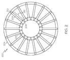
- FIG. 2 is a simplified cross section view of a turbine rotor component that may be used in the engine of FIG. 1 ;
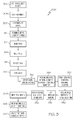
- FIG. 3 is a flowchart of a process that may used to manufacture the turbine rotor component of FIG. 2 ;
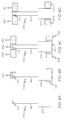
- FIGs. 4A - 4D are simplified schematic representations of a portion of a first embodiment of the turbine rotor component of FIG. 2 , shown at various stages of one embodiment of the process of FIG. 3 ;
- FIGs. 5A and 5B depict alternative embodiments of the process of FIG. 3 ;
- FIG. 6 is a diagram of a blade, with an as-cast segmented shroud, that may be used in a second embodiment of the turbine rotor component of FIG. 2 ;
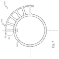
- FIG. 7 is a diagram of bi-cast blade ring, with an as-cast shroud, depicted as used in the second embodiment of the turbine rotor component of FIG. 2 ;
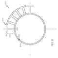
- FIG. 8 is a machined bi-cast blade ring with a segmented as-cast shroud, depicted as used in the second embodiment of the turbine rotor component of FIG. 2 ;
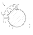
- FIG. 9 is a diagram of a bi-cast dual alloy turbine disk with an as-cast segmented shroud, depicted as used in the second embodiment of the turbine rotor component of FIG. 2 ;
- FIG. 10 is a diagram of a bi-cast blade ring, depicted as used in the first embodiment of the turbine rotor component of FIG. 2 .
- FIG. 1 An exemplary embodiment of a multi-spool turbofan gas turbine jet engine 100 is depicted in FIG. 1 , and includes an intake section 102, a compressor section 104, a combustion section 106, a turbine section 108, and an exhaust section 110.
- the intake section 102 includes a fan 112, which is mounted in a fan case 114.
- the fan 112 draws air into the intake section 102 and accelerates it.
- a fraction of the accelerated air exhausted from the fan 112 is directed through a bypass section 116 disposed between the fan case 114 and an engine cowl 118, and provides a forward thrust.
- the remaining fraction of air exhausted from the fan 112 is directed into the compressor section 104.
- the compressor section 104 includes two compressors, an intermediate pressure compressor 120, and a high pressure compressor 122.
- the intermediate pressure compressor 120 raises the pressure of the air directed into it from the fan 112, and directs the compressed air into the high pressure compressor 122.
- the high pressure compressor 122 compresses the air still further, and directs a majority of the high pressure air into the combustion section 106.
- a fraction of the compressed air bypasses the combustion section 106 and is used to cool, among other components, turbine blades in the turbine section 108.
- the combustion section 106 which includes an annular combustor 124, the high pressure air is mixed with fuel and combusted. The high-temperature combusted air is then directed into the turbine section 108.
- the turbine section 108 includes three turbines disposed in axial flow series, a high pressure turbine 126, an intermediate pressure turbine 128, and a low pressure turbine 130.
- the high-temperature combusted air from the combustion section 106 expands through each turbine, causing it to rotate.
- the air is then exhausted through a propulsion nozzle 132 disposed in the exhaust section 110, providing addition forward thrust.
- each drives equipment in the engine 100 via concentrically disposed shafts or spools.
- the high pressure turbine 126 drives the high pressure compressor 122 via a high pressure spool 134
- the intermediate pressure turbine 128 drives the intermediate pressure compressor 120 via an intermediate pressure spool 136
- the low pressure turbine 130 drives the fan 112 via a low pressure spool 138.
- Each of the turbines 126-130 in the turbine section 108 includes a plurality of stators (not shown in FIG. 1 ) and rotary blades (not shown in FIG. 1 ).
- the stators are used to direct a portion of the combusted air from the combustion section 106 onto the rotary blades.
- the rotary blades in turn cause the associate turbines 126-130 to rotate.
- FIG. 2 provides a simplified cross section view of a first exemplary embodiment of a turbine rotor component 200 that can be used in any one of a number of different types of turbines, including, among others, high, intermediate, and low pressure turbines 126, 128, and 130 of the turbine section 108 of the engine 100 of FIG. 1 .
- the turbine rotor component 200 includes an inner disk 202, an outer shroud ring 204, and a plurality of turbine blades 206 coupled to and extending between the inner disk 202 and the outer shroud ring 204.
- the outer shroud ring 204 is designed to minimize air loss in the engine 100 as air flows through the turbine section 108.
- the turbine blades 206 are preferably single crystal blades, but may be of another suitable alloy, such as directionally solidified, or another type of alloy.
- the inner disk 202 and outer shroud ring 204 are preferably cast of an equiaxed metal alloy material, such as, for example, a nickel-based super alloy; however, it will be appreciated that the inner disk 202 and outer shroud ring 204 may be made of one or more other materials.
- each of the turbine blades 206 includes a blade root 208, a blade tip, 210, and an airfoil body 212.
- the blade root 208 is coupled to the inner disk 202
- the blade tip 210 is coupled to the outer shroud ring 204.
- the turbine blades 206 are individually cast of a suitable material, preferably a single crystal nickel super alloy.
- both the blade root 208 and the blade tip 210 are preferably electroplated with a noble metal, preferably platinum, to prevent oxidation during bi-casting.
- the turbine blades 206 are assembled into a mold and both, an inner and outer ring is bi-cast encapsulating the blade root 208 and the blade tip 210, respectively.
- the blade root 208 is preferably bonded to the inner shroud ring, and the blade tip is preferably bonded against an outer ring, via a diffusion bonding process.
- one or more different noble metals may be plated onto the blade roots 208 and/or blade tips 210 via any one of a number of different means, and/or that variations in coupling techniques may be used.
- the airfoil body 212 extends at least between the blade root 208 and the blade tip 210, and preferably has either a single crystal composition, a directionally solidified composition, or another composition that is resistant to the high temperatures typically encountered in gas turbine engine environments.
- the airfoil body 212 is most preferably made of a single crystal composition of a nickel-based super alloy; however, the airfoil body 212 can be made of different materials, and/or may have a different composition.
- FIG. 3 a flowchart is provided for a process 300 for manufacturing the turbine rotor component 200 depicted in FIG. 2 .
- the process 300 will be described below in connection with FIG. 2 as well as FIGs. 4A - 4D , which depict simplified schematic representations of a single turbine blade 206 and portions of an inner ring 400 and an outer ring 401, at various stages of the process 300, in accordance with a first embodiment.
- step 302 the process 300 begins with step 302, in which a plurality of single crystal turbine blades 206 are cast.
- FIG. 4A depicts one such turbine blade 206 casted in step 302.
- each turbine blade 206 is cast as either single crystal, or directionally solidified, and is well suited for the high temperatures generally encountered in turbine engines. It will be appreciated that the casting in step 302 can be performed using standard casting techniques known in the art.
- the as cast turbine blade 206 undergoes a first heat treatment step.
- the first heat treatment preferably includes a stepwise heat treatment process in a furnace. Sufficient temperatures are preferably used to at least substantially alleviate any residual stress on the turbine blade 206, and to avoid subsequent recrystalization that might otherwise adversely affect turbine blade 206 performance and/or wear.
- the blade root 208 and/or the blade tip 210 are electroplated, at least in part, with a noble metal, preferably platinum, to prevent oxidation, during bi-casting, of the surfaces to be diffusion bonded subsequent to the bi-casting operation.
- a noble metal preferably platinum
- the electroplating is conducted on the blade root 208 and the blade tip 210, resulting in multiple plating regions 402. While the blade root 208 and the blade tip 210 are both electroplated with a noble metal in the depicted embodiment, it will be appreciated that this may vary in other embodiments, and that various other steps may correspondingly vary.
- only one of the blade root 208 or blade tip 210 may be electroplated with a noble metal, and the bi-casting may only apply to one end or the other in such other embodiments, rather than to both ends in the depicted embodiment, as described herein.
- Each plating region 402 preferably includes a thin layer of platinum or other noble metal, which prevents oxidation in the area to be bi-cast into an inner ring and/or an outer ring.
- the noble metal layer of each plating region 402 is preferably less than two millimeters in thickness; however, the thickness of the noble metal layer, and/or various other aspects of the plating regions 402, may vary.
- the plating regions 402 may cover the entire blade root 208 and/or blade tip 210, or portions thereof. Platinum is preferably used for the electroplating in step 306; however, other noble metals may also be used, instead of or in addition to platinum.
- the turbine blades 206 are assembled into a mold, preferably in an annular arrangement.
- conventional investment casting processes are used to fabricate a shell for casting, and an inner ring is bi-cast encapsulating the blade root 208, and an outer ring is bi-cast encapsulating the blade tip 210.
- only an inner ring may be bi-cast.
- the bi-cast assembly is HIP diffusion bonded to create a metallurgical bond between the blade root 208 and the inner ring, and between the blade tip 210 and the outer ring.
- the inner ring is configured to hold the blade root 208 in place for diffusion bonding to an internal disk.
- the outer ring is preferably machined into a segmented shroud.
- step 312 wax is injected into the mold, in the volumes where the inner and outer shroud rings are to be cast.
- a ceramic shell is built.
- the shell may be built, using the wax, for the outer and/or inner rings, depending on the embodiment.
- FIG. 4C depicts a turbine blade 206 with accompanying wax 404 in one such embodiment, in which the wax 404 at least partially surrounds the plating regions 402 proximate the blade tip 210 and the blade root 208.
- this may vary in other embodiments.
- step 318 the wax is removed, preferably by melting and burning out the wax, for example in an autoclave and a furnace.
- a metal alloy is cast for the inner and outer rings.
- an equiaxed metal alloy such as a nickel-based super alloy is used for the casting in step 320; however, it will be appreciated that any one of a number of other metal alloys may be used.
- Figure 4D shows a portion of the completed turbine rotor component 200 in one embodiment following step 324, specifically including a turbine blade 206 coupled to the inner ring 400 and outer ring 401.
- the inner ring 400 is metallurgically bonded to the blade root 208
- the outer ring 401 is metallurgically bonded to the blade tip 210.
- the casting is a 360 degree ring of turbine blades 206 held in place at least by the bi-cast inner disk 202.
- the bi-cast assembly in step 324 is HIP diffusion bonded to create a structural metallurgical bond between the inner disk 202 and the blade roots 208, and an internal diameter of the bi-cast inner disk 202 is machined, in step 326, to a specified diameter and a disk of nickel super alloy is inserted in step 328.
- the assembly is also then preferably vacuum brazed in step 330 to a nickel alloy hub, in preparation for diffusion bonding.
- the brazed assembly is HIP diffusion bonded in step 331 using conventional technology creating a metallurgical bond between the outer shroud ring 204 and the inner disk 202, and the machining of the dual alloy turbine disk is continued in step 332.
- step 334 another round of heat treatment is applied, preferably in which the turbine rotor component 200 (including the turbine blades 206, the inner disk 202, and the outer shroud ring 204) are placed into a furnace and undergo a stepwise heat treatment in order to achieve appropriate mechanical properties.
- the dual alloy turbine rotor with bi-cast single crystal blades and as-cast segmented shroud is complete.
- the diffusion bonding interface is then preferably inspected in step 338.
- heat treatment steps may vary, and/or may not be necessary, in certain embodiments. It will also be appreciated that various other steps of the process 300 may vary, and/or may be conducted simultaneously or in an order different than that depicted in FIG. 3 and described above.
- FIGs. 5A and 5B two alternative preferred embodiments 600A and 600B, respectively, of a process for manufacturing a first embodiment and a second embodiment, respectively, of the turbine rotor component 200.
- a method for manufacturing a first embodiment of the turbine rotor component 200, with a dual alloy turbine rotor with bi-cast internal ring, single crystal airfoils, and as-cast segmented shroud is provided.
- initial single crystal airfoils with an as-cast shroud are cast using conventional single crystal or directional solidification casting technology.
- the blade root is plated with platinum or similar noble metal to prevent oxidation, during bi-casting, of the surfaces to be diffusion bonded subsequent to the bi-casting operation.
- the plated airfoils are then, in step 606A, assembled into a mold.
- step 608A Conventional investment casting processes are used to fabricate a shell for casting, and the investment cast mold is prepared in step 608A.
- the internal ring is bi-cast in step 610A, encapsulating the airfoil blade root.
- the casting is a 360 degree ring of blades held in place by a bi-cast internal ring.
- step 612A the bi-cast assembly is HIP diffusion bonded to create a structural metallurgical bond between the internal ring and blade roots.
- the internal diameter of the bi-cast ring is then machined to a specified diameter in step 614A, and a disk of nickel super alloy is inserted in step 616A.
- step 618A the assembly is vacuum brazed in preparation for diffusion bonding.
- step 620A the brazed assembly is HIP diffusion bonded using conventional technology, creating a metallurgical bond between the disk outer diameter and bi-cast ring inner diameter.
- step 624A After subsequent heat treatment (step 622A) and machining (step 624A), the dual alloy turbine rotor with bi-cast single crystal blades and as-cast segmented shroud is complete.
- the second embodiment of the turbine rotor component 200 is machined to a specified dimension exposing the blade root.
- a nickel alloy disk is inserted into the internal diameter, and a diffusion bonding process is completed to bond the nickel alloy disk to the inner ring internal diameter, resulting in a bi-cast dual alloy turbine rotor with bi-cast shroud and single crystal or similar airfoils.
- the method 600B for manufacturing this second embodiment begins in step 602B, in which individual blades are cast using conventional single crystal casting technology.
- step 604B both the blade tip and blade root are coated with platinum, or a similar noble metal, to prevent oxidation during bi-casting.
- step 606B the airfoils are assembled into a conventional investment casting mold and shelled.
- step 608B both inner diameter and outer diameter rings are bi-cast.
- the bi-cast assembly is HIP diffusion bonded, in step 610B, to create a metallurgical bond between the blade root and inner diameter ring and blade tip and the outer diameter ring.
- the intent of the inner diameter ring is to hold the blade root in place for diffusion bonding to an internal disk.
- the outer diameter ring will be machined into a segmented shroud.
- step 612B the internal surface of the inner diameter ring is machined to a specified diameter in step 612B.
- a nickel superalloy hub is then inserted, in step 614B, and vacuum brazed in place, in step 616B.
- step 618B the assembly is HIP diffusion bonded to create a metallurgical bond between the disk and internal bi-cast ring.
- step 620B heat treatment
- step 620B machining
- segmenting of the outer diameter bi-cast ring a dual alloy turbine rotor with integral nickel alloy disk, single crystal blades, and bi-cast segmented shroud results.
- the diffusion bonded interface is then preferably inspected in step 624B.
- FIGs. 6-9 show a second embodiment of the turbine rotor component 200 during different stages of manufacture.
- the as-cast turbine blades 206 are individually cast and include an airfoil body 212, a blade root 208, and a blade tip 210.
- the as-cast blade root 208 is plated with a noble metal, such as platinum, to thereby form a platinum coating 702, to prevent oxidation during bi-casting.
- a plurality of such as-cast turbine blades 206 are assembled into a ring, and an inner ring 802 is bi-cast encapsulating a blade root 208.
- the turbine rotor component 200 thus takes the form of a bi-cast blade ring assembly comprising an inner ring 802, an airfoil body 212, and an as-cast blade tip 210.
- the inner ring 802 is bi-cast of a preferably equiaxed metal alloy material, such as, for example, a nickel-based super alloy.
- the bi-cast inner ring 802 is then diffusion bonded using process well known in the art such as HIP, or any one of various other techniques known in the art, preferably yielding a monolithic, diffusion bonded, bi-cast, shrouded blade ring. Also, as shown in FIG. 8 , an inner ring internal diameter 902 is machined to a specified diameter exposing the as-cast blade root 208 on an internal diameter of the inner ring 802.
- a nickel alloy hub 904 is inserted into the inner ring 802.
- a diffusion bonding process is preferably completed to bond the nickel alloy hub to the inner ring internal diameter 902 using one or more processes known in the art, such as HIP, and/or one or more other processes.
- the assembly comprises a dual alloy turbine disk comprising a fine grain nickel alloy hub 904, a plurality of single crystal airfoil turbine blades 206, and remnant bi-cast material between turbine blades 206 to be bonded to a disk 906.
- the turbine rotor component 200 and/or various components thereof can also take various other forms in various stages of development in other embodiments, and/or can be implemented in connection with any number of different types of devices and/or systems.
- FIG. 10 depicts the turbine rotor component 200 in accordance with the first exemplary embodiment discussed further above (including a bi-cast inner ring and a bi-cast outer shroud ring) after the diffusion bonding process is completed, and the turbine rotor component 200 is formed into a monolithic assembly. It will be appreciated these figures, and various portions of the turbine rotor component 200 and/or the methods for manufacturing the turbine rotor component 200, may vary in other embodiments.
- the processes 300, the turbine rotor component 200, and the steps and components thereof are potentially advantageous for any number of different turbine jet engines 100 and/or other engines or systems.
- the turbine rotor component 200 has a relatively high melting point and can withstand high temperatures typically encountered in turbine engine environments, due at least in part to the preferred single crystal composition of at least the airfoil body 212, and the optimal heat treatment enabled by the process 300 and the turbine rotor component 200 to prevent recrystalization.
- the metallurgical bonding, the preferred structure of the turbine rotor component 200 as a monolithic material when completed, and the use of a platinum or other noble metal plating, among other features, helps to further alleviate stress, withstand centrifugal forces, reduce wear, prevent oxidation that can interfere with desired bonding, and reduce costs and/or unwanted mechanical issues.
Landscapes
- Engineering & Computer Science (AREA)
- Mechanical Engineering (AREA)
- General Engineering & Computer Science (AREA)
- Chemical & Material Sciences (AREA)
- Materials Engineering (AREA)
- Ceramic Engineering (AREA)
- Chemical Kinetics & Catalysis (AREA)
- Electrochemistry (AREA)
- Metallurgy (AREA)
- Organic Chemistry (AREA)
- Turbine Rotor Nozzle Sealing (AREA)
Applications Claiming Priority (1)
| Application Number | Priority Date | Filing Date | Title |
|---|---|---|---|
| US11/737,949 US20090068016A1 (en) | 2007-04-20 | 2007-04-20 | Shrouded single crystal dual alloy turbine disk |
Publications (2)
| Publication Number | Publication Date |
|---|---|
| EP1983159A2 true EP1983159A2 (fr) | 2008-10-22 |
| EP1983159A3 EP1983159A3 (fr) | 2012-11-28 |
Family
ID=39415412
Family Applications (1)
| Application Number | Title | Priority Date | Filing Date |
|---|---|---|---|
| EP08103617A Withdrawn EP1983159A3 (fr) | 2007-04-20 | 2008-04-18 | Disque de turbine en double alliage monocristalline avec bande de recouvrement |
Country Status (3)
| Country | Link |
|---|---|
| US (2) | US20090068016A1 (fr) |
| EP (1) | EP1983159A3 (fr) |
| CA (1) | CA2629460A1 (fr) |
Cited By (4)
| Publication number | Priority date | Publication date | Assignee | Title |
|---|---|---|---|---|
| EP2230037A1 (fr) * | 2009-03-13 | 2010-09-22 | Honeywell International Inc. | Procédé de fabrication d'une hélice à microstructure double |
| WO2011042006A1 (fr) * | 2009-10-10 | 2011-04-14 | Mtu Aero Engines Gmbh | Procédé de soudage par fusion d'une pièce monocristalline et d'une pièce polycristalline, et rotor |
| FR2956598A1 (fr) * | 2010-02-23 | 2011-08-26 | Snecma | Procede d'usinage d'une piece en materiau monocristallin |
| EP3000556A1 (fr) * | 2014-09-24 | 2016-03-30 | Honeywell International Inc. | Rotors de turbine soudés carénés et procédés de fabrication associés |
Families Citing this family (15)
| Publication number | Priority date | Publication date | Assignee | Title |
|---|---|---|---|---|
| DE102008052247A1 (de) * | 2008-10-18 | 2010-04-22 | Mtu Aero Engines Gmbh | Bauteil für eine Gasturbine und Verfahren zur Herstellung des Bauteils |
| US8801388B2 (en) | 2010-12-20 | 2014-08-12 | Honeywell International Inc. | Bi-cast turbine rotor disks and methods of forming same |
| US20160024944A1 (en) * | 2013-03-14 | 2016-01-28 | United Technologies Corporation | Transient liquid pahse bonded turbine rotor assembly |
| WO2014204573A1 (fr) * | 2013-06-17 | 2014-12-24 | United Technologies Corporation | Profil aérodynamique composite relié à une emplanture métallique |
| GB2521588A (en) * | 2013-10-11 | 2015-07-01 | Reaction Engines Ltd | Turbine blades |
| US9844826B2 (en) | 2014-07-25 | 2017-12-19 | Honeywell International Inc. | Methods for manufacturing a turbine nozzle with single crystal alloy nozzle segments |
| US10072524B2 (en) * | 2015-02-10 | 2018-09-11 | United Technologies Corporation | Method of making a turbine wheel axial retention device |
| US9938834B2 (en) | 2015-04-30 | 2018-04-10 | Honeywell International Inc. | Bladed gas turbine engine rotors having deposited transition rings and methods for the manufacture thereof |
| US10294804B2 (en) | 2015-08-11 | 2019-05-21 | Honeywell International Inc. | Dual alloy gas turbine engine rotors and methods for the manufacture thereof |
| US10036254B2 (en) | 2015-11-12 | 2018-07-31 | Honeywell International Inc. | Dual alloy bladed rotors suitable for usage in gas turbine engines and methods for the manufacture thereof |
| US20190040749A1 (en) * | 2017-08-01 | 2019-02-07 | United Technologies Corporation | Method of fabricating a turbine blade |
| CN112276331B (zh) * | 2020-10-16 | 2022-03-15 | 中国航发四川燃气涡轮研究院 | 一种用于双辐板涡轮盘的焊接方法 |
| EP4249147A1 (fr) * | 2022-03-24 | 2023-09-27 | Lilium eAircraft GmbH | Procédé de fabrication d'un ensemble rotor |
| FR3161452A1 (fr) * | 2024-04-19 | 2025-10-24 | Safran Aircraft Engines | Procédé de fabrication d’un bipale pour distributeur de turbine haute pression et bipale obtenu par ce procédé |
| DE102024114373A1 (de) * | 2024-05-22 | 2025-11-27 | Rolls-Royce Deutschland Ltd & Co Kg | Rotorvorrichtung und Verfahren zur Herstellung einer Rotorvorrichtung |
Citations (2)
| Publication number | Priority date | Publication date | Assignee | Title |
|---|---|---|---|---|
| US4592120A (en) * | 1983-02-14 | 1986-06-03 | Williams International Corporation | Method for manufacturing a multiple property integral turbine wheel |
| US7157114B2 (en) * | 2003-09-29 | 2007-01-02 | General Electric Company | Platinum coating process |
Family Cites Families (28)
| Publication number | Priority date | Publication date | Assignee | Title |
|---|---|---|---|---|
| US4063939A (en) * | 1975-06-27 | 1977-12-20 | Special Metals Corporation | Composite turbine wheel and process for making same |
| US4051585A (en) * | 1976-07-26 | 1977-10-04 | United Technologies Corporation | Method of forming a turbine rotor |
| US4096615A (en) * | 1977-05-31 | 1978-06-27 | General Motors Corporation | Turbine rotor fabrication |
| US4417854A (en) * | 1980-03-21 | 1983-11-29 | Rockwell International Corporation | Compliant interface for ceramic turbine blades |
| DE3133158C1 (de) * | 1981-08-21 | 1982-12-16 | MTU Motoren- und Turbinen-Union München GmbH, 8000 München | Pressflaechen-Zwischenlage aus Metall und Verfahren zur Herstellung derselben |
| US4501776A (en) * | 1982-11-01 | 1985-02-26 | Turbine Components Corporation | Methods of forming a protective diffusion layer on nickel, cobalt and iron base alloys |
| US4728258A (en) * | 1985-04-25 | 1988-03-01 | Trw Inc. | Turbine engine component and method of making the same |
| US4961459A (en) * | 1989-01-25 | 1990-10-09 | Pcc Airfoils, Inc. | Method of making an improved turbine engine component |
| DE3916562A1 (de) * | 1989-05-20 | 1990-11-22 | Wall Giselher | Verfahren und hilfsteil zur herstellung einer zahntechnisch-prothetischen angussverbindung mit einer oxidbildenden legierung |
| US4987944A (en) * | 1989-11-13 | 1991-01-29 | Pcc Airfoils, Inc. | Method of making a turbine engine component |
| US5113583A (en) * | 1990-09-14 | 1992-05-19 | United Technologies Corporation | Integrally bladed rotor fabrication |
| US5489194A (en) * | 1990-09-14 | 1996-02-06 | Hitachi, Ltd. | Gas turbine, gas turbine blade used therefor and manufacturing method for gas turbine blade |
| US5238046A (en) * | 1990-09-20 | 1993-08-24 | Magotteaux International | Method of manufacturing a bimetal casting and wearing part produced by this method |
| FR2688154A1 (fr) * | 1992-03-04 | 1993-09-10 | Pechiney Recherche | Procede d'obtention de pieces bimateriaux par surmoulage d'un insert revetu d'un film metallique. |
| ES2063636B1 (es) * | 1992-04-23 | 1997-05-01 | Turbo Propulsores Ind | Conjunto de alabes de estator para motores de turbina de gas. |
| GB2271524B (en) * | 1992-10-16 | 1994-11-09 | Rolls Royce Plc | Bladed disc assembly by hip diffusion bonding |
| US5290143A (en) * | 1992-11-02 | 1994-03-01 | Allied Signal | Bicast vane and shroud rings |
| US5837385A (en) * | 1997-03-31 | 1998-11-17 | General Electric Company | Environmental coating for nickel aluminide components and a method therefor |
| US6254756B1 (en) * | 1999-08-11 | 2001-07-03 | General Electric Company | Preparation of components having a partial platinum coating thereon |
| EP1094131B1 (fr) * | 1999-10-23 | 2004-05-06 | ROLLS-ROYCE plc | Revêtement de protection contre la corrosion sur un article métallique et procédé pour produire un revêtement de protection contre la corrosion sur un article métallique |
| US6409473B1 (en) * | 2000-06-27 | 2002-06-25 | Honeywell International, Inc. | Low stress connection methodology for thermally incompatible materials |
| US6602548B2 (en) * | 2001-06-20 | 2003-08-05 | Honeywell International Inc. | Ceramic turbine blade attachment having high temperature, high stress compliant layers and method of fabrication thereof |
| US6609894B2 (en) * | 2001-06-26 | 2003-08-26 | General Electric Company | Airfoils with improved oxidation resistance and manufacture and repair thereof |
| US6672075B1 (en) * | 2002-07-18 | 2004-01-06 | University Of Maryland | Liquid cooling system for gas turbines |
| US6969240B2 (en) * | 2003-08-01 | 2005-11-29 | Honeywell International Inc. | Integral turbine composed of a cast single crystal blade ring diffusion bonded to a high strength disk |
| US20050265851A1 (en) * | 2004-05-26 | 2005-12-01 | Murali Madhava | Active elements modified chromium diffusion patch coating |
| US7560065B2 (en) * | 2004-10-08 | 2009-07-14 | Igor Troitski | Method and system for manufacturing of multi-component complex shape parts consisting of monolithic and powder materials working at different performance conditions |
| US20060239825A1 (en) * | 2005-04-21 | 2006-10-26 | Honeywell International Inc. | Bi-cast blade ring for multi-alloy turbine rotor |
-
2007
- 2007-04-20 US US11/737,949 patent/US20090068016A1/en not_active Abandoned
-
2008
- 2008-04-18 CA CA002629460A patent/CA2629460A1/fr not_active Abandoned
- 2008-04-18 EP EP08103617A patent/EP1983159A3/fr not_active Withdrawn
-
2014
- 2014-11-14 US US14/542,209 patent/US20150308273A1/en not_active Abandoned
Patent Citations (2)
| Publication number | Priority date | Publication date | Assignee | Title |
|---|---|---|---|---|
| US4592120A (en) * | 1983-02-14 | 1986-06-03 | Williams International Corporation | Method for manufacturing a multiple property integral turbine wheel |
| US7157114B2 (en) * | 2003-09-29 | 2007-01-02 | General Electric Company | Platinum coating process |
Cited By (4)
| Publication number | Priority date | Publication date | Assignee | Title |
|---|---|---|---|---|
| EP2230037A1 (fr) * | 2009-03-13 | 2010-09-22 | Honeywell International Inc. | Procédé de fabrication d'une hélice à microstructure double |
| WO2011042006A1 (fr) * | 2009-10-10 | 2011-04-14 | Mtu Aero Engines Gmbh | Procédé de soudage par fusion d'une pièce monocristalline et d'une pièce polycristalline, et rotor |
| FR2956598A1 (fr) * | 2010-02-23 | 2011-08-26 | Snecma | Procede d'usinage d'une piece en materiau monocristallin |
| EP3000556A1 (fr) * | 2014-09-24 | 2016-03-30 | Honeywell International Inc. | Rotors de turbine soudés carénés et procédés de fabrication associés |
Also Published As
| Publication number | Publication date |
|---|---|
| EP1983159A3 (fr) | 2012-11-28 |
| CA2629460A1 (fr) | 2008-10-20 |
| US20090068016A1 (en) | 2009-03-12 |
| US20150308273A1 (en) | 2015-10-29 |
Similar Documents
| Publication | Publication Date | Title |
|---|---|---|
| US20150308273A1 (en) | Shrouded single crystal dual alloy turbine disk | |
| US11143034B2 (en) | Multiple piece engine component | |
| EP1978208B1 (fr) | Procédé de fabrication des rotors de turbine multi-alliage | |
| EP1526252B1 (fr) | Procédé de production d'un rotor de turbine avec des propriétés triples | |
| US6190133B1 (en) | High stiffness airoil and method of manufacture | |
| US9115586B2 (en) | Axially-split radial turbine | |
| EP2058474A2 (fr) | Composant pour turbine à gaz et procédé pour sa fabrication | |
| EP2803820B1 (fr) | Rotor intégral de turbine refroidi par impact | |
| US8348614B2 (en) | Coolable airfoil trailing edge passage | |
| US8801388B2 (en) | Bi-cast turbine rotor disks and methods of forming same | |
| EP1970147A2 (fr) | Composant de rotor en superalliage et procédé de fabrication | |
| JP2017150475A (ja) | 翼形部の後縁冷却 | |
| JP2017172583A (ja) | フィルム孔を備えたタービンエンジン用の構成要素 | |
| US10792771B2 (en) | Method of making integrally bladed rotor | |
| US10422228B2 (en) | Manufacturing a monolithic component with discrete portions formed of different metals | |
| US6640546B2 (en) | Foil formed cooling area enhancement | |
| JP2010127280A (ja) | 応力を低下させたベーン | |
| US11814979B1 (en) | Systems and methods of hybrid blade tip repair | |
| US20240263557A1 (en) | Systems and methods of blade tip repair and manufacturing using field assisted sintering | |
| US20230012375A1 (en) | Radial flow turbine rotor with internal fluid cooling | |
| US10822959B2 (en) | Blade tip cooling |
Legal Events
| Date | Code | Title | Description |
|---|---|---|---|
| PUAI | Public reference made under article 153(3) epc to a published international application that has entered the european phase |
Free format text: ORIGINAL CODE: 0009012 |
|
| AK | Designated contracting states |
Kind code of ref document: A2 Designated state(s): AT BE BG CH CY CZ DE DK EE ES FI FR GB GR HR HU IE IS IT LI LT LU LV MC MT NL NO PL PT RO SE SI SK TR |
|
| AX | Request for extension of the european patent |
Extension state: AL BA MK RS |
|
| PUAL | Search report despatched |
Free format text: ORIGINAL CODE: 0009013 |
|
| AK | Designated contracting states |
Kind code of ref document: A3 Designated state(s): AT BE BG CH CY CZ DE DK EE ES FI FR GB GR HR HU IE IS IT LI LT LU LV MC MT NL NO PL PT RO SE SI SK TR |
|
| AX | Request for extension of the european patent |
Extension state: AL BA MK RS |
|
| RIC1 | Information provided on ipc code assigned before grant |
Ipc: F01D 5/30 20060101ALI20121023BHEP Ipc: F01D 5/06 20060101AFI20121023BHEP Ipc: F01D 5/28 20060101ALI20121023BHEP Ipc: F01D 5/34 20060101ALI20121023BHEP |
|
| 17P | Request for examination filed |
Effective date: 20080418 |
|
| 17Q | First examination report despatched |
Effective date: 20130318 |
|
| AKX | Designation fees paid |
Designated state(s): FR GB |
|
| REG | Reference to a national code |
Ref country code: DE Ref legal event code: R108 |
|
| REG | Reference to a national code |
Ref country code: DE Ref legal event code: R108 Effective date: 20130731 |
|
| RAP1 | Party data changed (applicant data changed or rights of an application transferred) |
Owner name: HONEYWELL INTERNATIONAL INC. |
|
| STAA | Information on the status of an ep patent application or granted ep patent |
Free format text: STATUS: THE APPLICATION IS DEEMED TO BE WITHDRAWN |
|
| 18D | Application deemed to be withdrawn |
Effective date: 20180703 |