EP1983162A2 - Dispositif de connexion des ensembles de culbuteur, de soupape ou à injection dans des moteurs de combustion interne - Google Patents
Dispositif de connexion des ensembles de culbuteur, de soupape ou à injection dans des moteurs de combustion interne Download PDFInfo
- Publication number
- EP1983162A2 EP1983162A2 EP08005470A EP08005470A EP1983162A2 EP 1983162 A2 EP1983162 A2 EP 1983162A2 EP 08005470 A EP08005470 A EP 08005470A EP 08005470 A EP08005470 A EP 08005470A EP 1983162 A2 EP1983162 A2 EP 1983162A2
- Authority
- EP
- European Patent Office
- Prior art keywords
- connection device
- button
- internal combustion
- valve
- recess
- Prior art date
- Legal status (The legal status is an assumption and is not a legal conclusion. Google has not performed a legal analysis and makes no representation as to the accuracy of the status listed.)
- Withdrawn
Links
Images

Classifications
-
- F—MECHANICAL ENGINEERING; LIGHTING; HEATING; WEAPONS; BLASTING
- F01—MACHINES OR ENGINES IN GENERAL; ENGINE PLANTS IN GENERAL; STEAM ENGINES
- F01L—CYCLICALLY OPERATING VALVES FOR MACHINES OR ENGINES
- F01L1/00—Valve-gear or valve arrangements, e.g. lift-valve gear
- F01L1/12—Transmitting gear between valve drive and valve
- F01L1/18—Rocking arms or levers
- F01L1/181—Centre pivot rocking arms
-
- F—MECHANICAL ENGINEERING; LIGHTING; HEATING; WEAPONS; BLASTING
- F01—MACHINES OR ENGINES IN GENERAL; ENGINE PLANTS IN GENERAL; STEAM ENGINES
- F01L—CYCLICALLY OPERATING VALVES FOR MACHINES OR ENGINES
- F01L1/00—Valve-gear or valve arrangements, e.g. lift-valve gear
- F01L1/12—Transmitting gear between valve drive and valve
- F01L1/14—Tappets; Push rods
- F01L1/146—Push-rods
-
- F—MECHANICAL ENGINEERING; LIGHTING; HEATING; WEAPONS; BLASTING
- F01—MACHINES OR ENGINES IN GENERAL; ENGINE PLANTS IN GENERAL; STEAM ENGINES
- F01L—CYCLICALLY OPERATING VALVES FOR MACHINES OR ENGINES
- F01L1/00—Valve-gear or valve arrangements, e.g. lift-valve gear
- F01L1/20—Adjusting or compensating clearance
- F01L1/22—Adjusting or compensating clearance automatically, e.g. mechanically
-
- F—MECHANICAL ENGINEERING; LIGHTING; HEATING; WEAPONS; BLASTING
- F01—MACHINES OR ENGINES IN GENERAL; ENGINE PLANTS IN GENERAL; STEAM ENGINES
- F01L—CYCLICALLY OPERATING VALVES FOR MACHINES OR ENGINES
- F01L2810/00—Arrangements solving specific problems in relation with valve gears
- F01L2810/02—Lubrication
Definitions
- the present invention relates to a connection device for connecting rocker, valve or injection assemblies in internal combustion engines.
- the above ball coupling comprises a spherical head screw or insert, including a vertical element coupled to the rocker assembly, for engaging in a recess defined in a button element which, by engaging with a driving plate, allows force to be transferred to a component to be driven, usually comprising the valve or injection assembly, as is shown in figures 1 and 2 .
- Said button is held on the insert head portion by a resilient element or O-ring, preventing the button from disengaging from its recess, to be properly mounted on the engine.
- the rocker conventionally comprises a plurality of throughgoing holes communicating with a further hole formed in the insert leading to the recess, therethrough yet another hole for allowing oil to be directed toward the plate is formed.
- lubricating oil is conveyed to the plate through the lubricating hole which is normally axially directed or which, in same cases, is slanted, as shown in figure 3 , to facilitate a proper distribution of the lubricating oil due to the natural trend of the button to turn on itself.
- said button is made by a turning process, or a more inexpensive cold pressing process, and then it being further thermally processed to achieve the desired mechanical properties. Finally, said button is further subjected to optional finishing operations.
- the aim of the present invention is to overcome the above mentioned problem, by providing a connection device for connecting a rocker assembly with a valve assembly, or an injection assembly in an internal combustion engine, allowing the lubricating oil to be optimally distributed even if the device is made by a cold pressing method.
- a main object of the invention is to provide such a connection device which always provide an even distribution of the lubricating oil on contacting surfaces between the button and driving plate.
- Yet another object of the present invention is to provide such a connection device which, owing to its specifically designed construction, is very reliable and safe in operation.
- Yet another object of the present invention is to provide such a connection device which can be easily made starting from easily available elements and materials, and which, moreover, is very competitive from a mere economic standpoint.
- connection device for connecting a rocker assembly, a valve assembly or an injection assembly, in an internal combustion engine
- said connection device comprising a button defining a recess for receiving an insert coupled to said rocker assembly, said recess having lubricating hole
- said connection device also comprises, on a face of, said button contacting a driving plate, a slot extending from said lubricating hole to an outer periphery of said button.
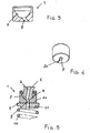
- connection device for connecting a rocker assembly, a valve assembly or an injection assembly in an internal combustion engine, which is illustrated, by way of an indicative, but not limitative example, in the accompanying drawings, where:
- connection device for connecting a rocker assembly, a valve assembly or an injection assembly in an internal combustion engine comprises a button, generally indicated by the reference number 1, defining a substantially half-spherical recess 2, for engaging therein a spherical head 3 of an insert or screw 4, to be coupled to a rocker 5.
- Said insert or screw 4 comprises a conventional lubricating duct.6 communicating with a further duct 7 defined in the rocker and leading to the recess where a hole 8 facing to a driving plate 9 associated with a spring 10 for coupling to a valve or an injection assembly is formed.
- the main feature of the invention is that, on the button surface or face contacting the driving plate 9, a slot 20, extending from the hole 8 and leading to the button periphery, is formed.
- the slot 10 which preferably radially extends, operates to facilitate a distribution of oil through the overall contacting surface, owing to the trend of the button to turn on itself, as the engine is operated, thereby spreading lubricating oil through the overall contacting surface.
- the small size of the slot is such as not to considerably increase the contact effort on the remaining contact surface, thereby the original function of the button is held unalterated.
- a further important feature to be stressed is that the slot can be directly made by a cold pressing operation, at a very low cost.
- the used materials, as well as the contingent size and shapes can be any, depending to requirements.
Landscapes
- Engineering & Computer Science (AREA)
- Mechanical Engineering (AREA)
- General Engineering & Computer Science (AREA)
- Valve-Gear Or Valve Arrangements (AREA)
- Fuel-Injection Apparatus (AREA)
- Output Control And Ontrol Of Special Type Engine (AREA)
- Lubrication Of Internal Combustion Engines (AREA)
Applications Claiming Priority (1)
| Application Number | Priority Date | Filing Date | Title |
|---|---|---|---|
| IT000779A ITMI20070779A1 (it) | 2007-04-17 | 2007-04-17 | Dispositivo di connessione tra il bilanciere e le valvole od il gruppo di iniezione in motori a combustione interna |
Publications (2)
| Publication Number | Publication Date |
|---|---|
| EP1983162A2 true EP1983162A2 (fr) | 2008-10-22 |
| EP1983162A3 EP1983162A3 (fr) | 2009-12-09 |
Family
ID=39688847
Family Applications (1)
| Application Number | Title | Priority Date | Filing Date |
|---|---|---|---|
| EP08005470A Withdrawn EP1983162A3 (fr) | 2007-04-17 | 2008-03-25 | Dispositif de connexion des ensembles de culbuteur, de soupape ou à injection dans des moteurs de combustion interne |
Country Status (3)
| Country | Link |
|---|---|
| US (1) | US20080257293A1 (fr) |
| EP (1) | EP1983162A3 (fr) |
| IT (1) | ITMI20070779A1 (fr) |
Cited By (1)
| Publication number | Priority date | Publication date | Assignee | Title |
|---|---|---|---|---|
| CN114542228A (zh) * | 2022-02-23 | 2022-05-27 | 常柴股份有限公司 | 一种能够降低损耗的内燃机推杆 |
Families Citing this family (6)
| Publication number | Priority date | Publication date | Assignee | Title |
|---|---|---|---|---|
| JP4578547B2 (ja) * | 2008-07-10 | 2010-11-10 | 株式会社オティックス | 潤滑油供給路を有するロッカーアーム |
| JP5241533B2 (ja) * | 2009-01-19 | 2013-07-17 | 株式会社オティックス | ロッカアーム |
| US9551242B2 (en) * | 2014-11-24 | 2017-01-24 | Caterpillar Inc. | Rocker arm for engines |
| JP6899939B1 (ja) * | 2020-03-26 | 2021-07-07 | 株式会社オティックス | 動弁装置 |
| DE102021100952A1 (de) | 2021-01-19 | 2022-07-21 | Schaeffler Technologies AG & Co. KG | Kipphebel in Massivbauweise für einen Ventiltrieb einer Schwerlastbrennkraftmaschine |
| DE102021102690A1 (de) | 2021-02-05 | 2022-08-11 | Schaeffler Technologies AG & Co. KG | Kipphebel in Massivbauweise für einen Ventiltrieb einer Schwerlastbrennkraftmaschine |
Family Cites Families (4)
| Publication number | Priority date | Publication date | Assignee | Title |
|---|---|---|---|---|
| CH646498A5 (de) * | 1980-05-07 | 1984-11-30 | Faester Gmbh & Co Kg | Schraube mit kreuzfoermig im schraubenkopf angeordneten schraubendrehschlitzen. |
| US6273042B1 (en) * | 1999-06-14 | 2001-08-14 | Amsted Industries Incorporated | Rocker assemblies for control of engine valves and method of assembling such rocker assemblies |
| US6807932B2 (en) * | 2001-11-22 | 2004-10-26 | Ntn Corporation | Rocker arm |
| SE528784C2 (sv) * | 2005-06-07 | 2007-02-13 | Scania Cv Abp | Anordning för överföring av rörelse från en vipparm till en ventilinrättning hos en förbränningsmotor och en förbränningsmotor innefattande en sådan anordning |
-
2007
- 2007-04-17 IT IT000779A patent/ITMI20070779A1/it unknown
-
2008
- 2008-03-24 US US12/077,997 patent/US20080257293A1/en not_active Abandoned
- 2008-03-25 EP EP08005470A patent/EP1983162A3/fr not_active Withdrawn
Cited By (1)
| Publication number | Priority date | Publication date | Assignee | Title |
|---|---|---|---|---|
| CN114542228A (zh) * | 2022-02-23 | 2022-05-27 | 常柴股份有限公司 | 一种能够降低损耗的内燃机推杆 |
Also Published As
| Publication number | Publication date |
|---|---|
| ITMI20070779A1 (it) | 2008-10-18 |
| US20080257293A1 (en) | 2008-10-23 |
| EP1983162A3 (fr) | 2009-12-09 |
Similar Documents
| Publication | Publication Date | Title |
|---|---|---|
| EP1983162A2 (fr) | Dispositif de connexion des ensembles de culbuteur, de soupape ou à injection dans des moteurs de combustion interne | |
| US7802559B2 (en) | Hold-down device for a fuel injection device, and fuel injection device | |
| US8707930B2 (en) | Hold-down device for a fuel injection device | |
| EP2941559B1 (fr) | Ensemble d'injection de carburant | |
| US20130340714A1 (en) | Coupling Device | |
| US7048521B2 (en) | High pressure fuel supply pump with an intake valve member and a discharge valve member aligned along a plunger axis | |
| US20070175450A1 (en) | Support element | |
| KR20110000582A (ko) | 커플링 장치 | |
| EP1715156A3 (fr) | Soupape de thermostat pour un sytème de refroidissement d'un moteur à combustion interne | |
| US20210310454A1 (en) | Engine | |
| US8555841B2 (en) | Coupling plate between valves | |
| US6553969B1 (en) | Device for assembling and dismantling a fuel injection valve | |
| US7540435B2 (en) | Pressure-effected interconnection of a metal part and a plastic part | |
| US3116647A (en) | Engine rocker arm | |
| EP1591652A3 (fr) | Soupape d'injection de combustible gazeux | |
| WO2005038235A3 (fr) | Dispositif d'injection de carburant, notamment pour un moteur a combustion interne a injection directe de carburant | |
| US7819379B2 (en) | Attachment of an armature to a valve needle in a fuel injector control valve | |
| JP2015031230A (ja) | オイルジェット | |
| JP4133718B2 (ja) | ロッカーアームフリクションプレート | |
| EP1862668B1 (fr) | Dispositif de couplage et assemblage de liaison | |
| KR101774699B1 (ko) | 솔리드 타입 회전방지부를 갖는 롤러 태핏 장치 | |
| US9488142B2 (en) | Locating pin | |
| JP7836296B2 (ja) | 燃料ポンプ装置、システム、及び方法 | |
| JP3129977U (ja) | ロッカーアーム | |
| CN107443068B (zh) | 一种化油器的压装工艺 |
Legal Events
| Date | Code | Title | Description |
|---|---|---|---|
| PUAI | Public reference made under article 153(3) epc to a published international application that has entered the european phase |
Free format text: ORIGINAL CODE: 0009012 |
|
| AK | Designated contracting states |
Kind code of ref document: A2 Designated state(s): AT BE BG CH CY CZ DE DK EE ES FI FR GB GR HR HU IE IS IT LI LT LU LV MC MT NL NO PL PT RO SE SI SK TR |
|
| AX | Request for extension of the european patent |
Extension state: AL BA MK RS |
|
| PUAL | Search report despatched |
Free format text: ORIGINAL CODE: 0009013 |
|
| AK | Designated contracting states |
Kind code of ref document: A3 Designated state(s): AT BE BG CH CY CZ DE DK EE ES FI FR GB GR HR HU IE IS IT LI LT LU LV MC MT NL NO PL PT RO SE SI SK TR |
|
| AX | Request for extension of the european patent |
Extension state: AL BA MK RS |
|
| RIC1 | Information provided on ipc code assigned before grant |
Ipc: F01M 9/10 20060101ALI20091030BHEP Ipc: F01L 1/18 20060101AFI20080822BHEP |
|
| AKX | Designation fees paid |
Designated state(s): AT BE BG CH CY CZ DE DK EE ES FI FR GB GR HR HU IE IS IT LI LT LU LV MC MT NL NO PL PT RO SE SI SK TR |
|
| STAA | Information on the status of an ep patent application or granted ep patent |
Free format text: STATUS: THE APPLICATION IS DEEMED TO BE WITHDRAWN |
|
| 18D | Application deemed to be withdrawn |
Effective date: 20100610 |