EP1983242A1 - Vorrichtung zur Aufrechterhaltung der Entlüftungsleitungen von Gehäusen von Armaturenelementen vom Ventiltyp - Google Patents
Vorrichtung zur Aufrechterhaltung der Entlüftungsleitungen von Gehäusen von Armaturenelementen vom Ventiltyp Download PDFInfo
- Publication number
- EP1983242A1 EP1983242A1 EP08300169A EP08300169A EP1983242A1 EP 1983242 A1 EP1983242 A1 EP 1983242A1 EP 08300169 A EP08300169 A EP 08300169A EP 08300169 A EP08300169 A EP 08300169A EP 1983242 A1 EP1983242 A1 EP 1983242A1
- Authority
- EP
- European Patent Office
- Prior art keywords
- module
- column
- cavity
- conduits
- ducts
- Prior art date
- Legal status (The legal status is an assumption and is not a legal conclusion. Google has not performed a legal analysis and makes no representation as to the accuracy of the status listed.)
- Withdrawn
Links
- 239000000463 material Substances 0.000 claims description 3
- 230000002093 peripheral effect Effects 0.000 claims description 3
- 230000000903 blocking effect Effects 0.000 claims description 2
- 238000012423 maintenance Methods 0.000 claims description 2
- 238000006073 displacement reaction Methods 0.000 abstract description 3
- 208000031968 Cadaver Diseases 0.000 description 4
- 238000009434 installation Methods 0.000 description 4
- 230000000295 complement effect Effects 0.000 description 3
- 239000000725 suspension Substances 0.000 description 3
- 238000004519 manufacturing process Methods 0.000 description 2
- 125000006850 spacer group Chemical group 0.000 description 2
- 238000004378 air conditioning Methods 0.000 description 1
- 238000010438 heat treatment Methods 0.000 description 1
- 238000011065 in-situ storage Methods 0.000 description 1
- 230000014759 maintenance of location Effects 0.000 description 1
- 238000000465 moulding Methods 0.000 description 1
- 238000010137 moulding (plastic) Methods 0.000 description 1
- 230000001681 protective effect Effects 0.000 description 1
- 238000010926 purge Methods 0.000 description 1
- 238000005057 refrigeration Methods 0.000 description 1
- 238000003860 storage Methods 0.000 description 1
- 238000009423 ventilation Methods 0.000 description 1
Images

Classifications
-
- F—MECHANICAL ENGINEERING; LIGHTING; HEATING; WEAPONS; BLASTING
- F24—HEATING; RANGES; VENTILATING
- F24F—AIR-CONDITIONING; AIR-HUMIDIFICATION; VENTILATION; USE OF AIR CURRENTS FOR SCREENING
- F24F13/00—Details common to, or for air-conditioning, air-humidification, ventilation or use of air currents for screening
- F24F13/02—Ducting arrangements
-
- F—MECHANICAL ENGINEERING; LIGHTING; HEATING; WEAPONS; BLASTING
- F16—ENGINEERING ELEMENTS AND UNITS; GENERAL MEASURES FOR PRODUCING AND MAINTAINING EFFECTIVE FUNCTIONING OF MACHINES OR INSTALLATIONS; THERMAL INSULATION IN GENERAL
- F16L—PIPES; JOINTS OR FITTINGS FOR PIPES; SUPPORTS FOR PIPES, CABLES OR PROTECTIVE TUBING; MEANS FOR THERMAL INSULATION IN GENERAL
- F16L3/00—Supports for pipes, cables or protective tubing, e.g. hangers, holders, clamps, cleats, clips, brackets
- F16L3/22—Supports for pipes, cables or protective tubing, e.g. hangers, holders, clamps, cleats, clips, brackets specially adapted for supporting a number of parallel pipes at intervals
- F16L3/221—Supports for pipes, cables or protective tubing, e.g. hangers, holders, clamps, cleats, clips, brackets specially adapted for supporting a number of parallel pipes at intervals having brackets connected together by means of a common support
-
- F—MECHANICAL ENGINEERING; LIGHTING; HEATING; WEAPONS; BLASTING
- F16—ENGINEERING ELEMENTS AND UNITS; GENERAL MEASURES FOR PRODUCING AND MAINTAINING EFFECTIVE FUNCTIONING OF MACHINES OR INSTALLATIONS; THERMAL INSULATION IN GENERAL
- F16L—PIPES; JOINTS OR FITTINGS FOR PIPES; SUPPORTS FOR PIPES, CABLES OR PROTECTIVE TUBING; MEANS FOR THERMAL INSULATION IN GENERAL
- F16L3/00—Supports for pipes, cables or protective tubing, e.g. hangers, holders, clamps, cleats, clips, brackets
- F16L3/22—Supports for pipes, cables or protective tubing, e.g. hangers, holders, clamps, cleats, clips, brackets specially adapted for supporting a number of parallel pipes at intervals
- F16L3/223—Supports for pipes, cables or protective tubing, e.g. hangers, holders, clamps, cleats, clips, brackets specially adapted for supporting a number of parallel pipes at intervals each support having one transverse base for supporting the pipes
- F16L3/2235—Supports for pipes, cables or protective tubing, e.g. hangers, holders, clamps, cleats, clips, brackets specially adapted for supporting a number of parallel pipes at intervals each support having one transverse base for supporting the pipes each pipe being supported by a common element fastened to the base
-
- F—MECHANICAL ENGINEERING; LIGHTING; HEATING; WEAPONS; BLASTING
- F24—HEATING; RANGES; VENTILATING
- F24F—AIR-CONDITIONING; AIR-HUMIDIFICATION; VENTILATION; USE OF AIR CURRENTS FOR SCREENING
- F24F13/00—Details common to, or for air-conditioning, air-humidification, ventilation or use of air currents for screening
Definitions
- the invention relates to the technical sector of valve elements of the type valves, valves, faucets and means and accessories used for their installation in situ.
- valves valves, valves, underground valves or integrated in a protective installation
- the use of valves, valves, underground valves or integrated in a protective installation are known that are arranged with one or two vent ducts for purge, pressure and other functions.
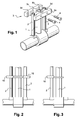
- the duct or conduits are arranged parallel to the vertical column of the valve body, as shown figure 1 drawings, this column being arranged to allow the control and opening / closing of the valve.
- valve will be used to generally identify all equivalent means.
- connecting struts (3) which have the function of ensure the perfect holding in position and spacing of the duct or ducts relative to the column, and this, despite the surrounding environment that can be hostile.
- the connecting struts (3) are constituted as it appears figure 1 by two flanges (3a-3b) which each have a central cell (3c) semi-cylindrical to enclose the opposite part of the column, and two lateral cells (3d) semi-cylindrical arranged on either side of the central cavity to enclose the parts facing the vent ducts (2).
- the connection is made by transverse bolting (4) between the flanges through threaded holes formed therein.
- the holding device described above has many disadvantages.
- the mounting of the flanges is impractical because the operator must with one hand hold them contiguous and clamped against each other, and then arrange the connection means of the bolting type by positioning them one by one, then tighten these with the aid of tools of the key type for maintaining the above-mentioned connecting struts (3) horizontally.
- the maneuver is not practical, positioning horizontality is not always assured.
- the connecting struts of the aforementioned type are limited to the use for a determined spacing of the lateral ducts relative to the column, so that it is necessary to have several sets of spacers to fit according to the equipment of the installation concerned.
- the cost price of the spacers remains as high. Their storage is bulky.
- a cable holding device in two complementary parts hinged together at one end and locked in position at the other end. These parts are themselves arranged with cavities of complementary profile defining different diameters for the conduit retention.
- the hinged closure and locking tab provides quick closure of the device.
- a gutter device for holding conduits or the like by means of detention. It is only in the document to allow the suspension of tubes in applications of heating, ventilation, air conditioning, refrigeration. In other words, the links that can be used only have an anti-escape function.
- Another aim was to design a new type of connection means that can be perfectly adjusted and assembled in any number of elements to ensure a quality of holding and spacing between the conduits and the valve column considered.
- Another object sought was to avoid the use of hand tools necessary for fixing the aforementioned connecting means, to ensure the locking or loosening of the bolt, as required by the solution of the prior art.
- the Applicant's research approach led to the design of a device for holding vent ducts with respect to the column formed on the valve body which is extremely practical to be placed by the operator and a very simple manufacturing design.
- the device for holding the valve body vent lines of the type valve characterized in that it comprises at least one monobloc module made of a plastic material and capable of being arranged in a horizontal plane around the lateral duct or ducts and the column of the valve body, and in that the module presents a pincer-shaped configuration with a rear base which is arranged with at least one cavity to surround the lateral duct considered and extending at the front by two branches arranged facing one another, and defining between them a a semi-cylindrical central cavity for surrounding the main column of the valve body, and in that the two branches are capable of elastic spacing relative to each other, the module having a global configuration in the form of a clamp, and in that each module has openings along their peripheral edge, on the one hand, on the side of the rear base and facing the cavity or recesses surrounding the conduit and, on the other hand, on both sides of each of the branch portions surrounding the central cavity which are capable of allowing the positioning of elastic fixing links, and in that the links
- the device according to the invention for maintaining the vent ducts with respect to the column of the valve body is thus constituted by at least one module (10) made in one piece of plastic material and capable of being arranged in a horizontal plane around the lateral ducts and the column of the valve body.
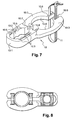
- the module (10) has a pincer-shaped configuration with a rear base (10-1) which is arranged with at least one cavity (10.2) to surround the respective lateral duct and extending at the front by two arms (10.3). ) disposed opposite one another, and defining between them a cavity (10-4) central semi-cylindrical to surround the main column of the valve body.
- the two branches are capable of an elastic spacing relative to each other, the module having a global configuration in the form of a clamp.
- the rear base of the module has one or more cavities of lesser section successively arranged and which are likely to correspond to the section of the side vents ducts. It is therefore understood that it is possible to position the ducts in one of the cavities shaped for this purpose, thereby causing the setting gap to be modified.
- the central part is of greater curvilinear section to surround the column.
- the front part of the module is established in thickness (e1) on half the thickness (e) of the rear base of the module considered, so that it is possible by reversibility of have another identical module to come to position the corresponding support on the first.
- Each module has openings (10.5) along their peripheral edge (10.6) on the side of the rear heel and on either side of the branch portion (10.3) which are capable of allowing the positioning of the elastic links (11) of fixation.
- the relative positioning of two superposed modules relative to each other is established so that there is a self-locking of the parts between them, so as to avoid a movement of one module relative to the other .
- FIG 8 an example of maintaining the central column (1) and a conduit (2) vents with the addition of different links (11) which are positioned in the openings (10.5 - 10.6) formed on each module.
- These links in addition to the function of connecting and closing the module considered, have the other function of avoiding lateral displacement of the central column and the duct or ducts while being in contact and contact with said column (4) and the one or more ducts (2).
- These links (11) arranged on both sides of the ducts and in combination with them can thus, as shown figure 8 , undergo a partial deformation to fit the profiles of the column and the duct or ducts with firm tightening.
- the central cavity (10-4) can be arranged conspicuously with pins or protruding shapes which are likely to be in contact with the central column to reinforce the maintenance of the module on the column and to prevent the all down during assembly and blocking modules. These pins or projections are obtained during the molding of the module.
- the other cavities (10-2) may, if necessary, be arranged with pins or similar projecting shapes.
- the invention is simple and easy to implement, low manufacturing cost.
- the modules are easy to position and it is no longer necessary to have hand tools to ensure their connection, as was done according to the prior art.
Landscapes
- Engineering & Computer Science (AREA)
- General Engineering & Computer Science (AREA)
- Mechanical Engineering (AREA)
- Chemical & Material Sciences (AREA)
- Combustion & Propulsion (AREA)
- Valve Housings (AREA)
- Duct Arrangements (AREA)
Applications Claiming Priority (1)
| Application Number | Priority Date | Filing Date | Title |
|---|---|---|---|
| FR0754539A FR2915263A1 (fr) | 2007-04-18 | 2007-04-18 | Dispositif de maintien des conduits d'events de corps d'elements de robinetterie du type vanne. |
Publications (1)
| Publication Number | Publication Date |
|---|---|
| EP1983242A1 true EP1983242A1 (de) | 2008-10-22 |
Family
ID=38610904
Family Applications (1)
| Application Number | Title | Priority Date | Filing Date |
|---|---|---|---|
| EP08300169A Withdrawn EP1983242A1 (de) | 2007-04-18 | 2008-04-01 | Vorrichtung zur Aufrechterhaltung der Entlüftungsleitungen von Gehäusen von Armaturenelementen vom Ventiltyp |
Country Status (4)
| Country | Link |
|---|---|
| EP (1) | EP1983242A1 (de) |
| KR (1) | KR20080093914A (de) |
| CN (1) | CN101290076A (de) |
| FR (1) | FR2915263A1 (de) |
Families Citing this family (2)
| Publication number | Priority date | Publication date | Assignee | Title |
|---|---|---|---|---|
| CN110594551B (zh) * | 2018-06-12 | 2021-04-20 | 深圳市光锦绿色科技有限公司 | 一种隐形显示屏、载体装置及安装方法 |
| CN216114849U (zh) * | 2021-07-26 | 2022-03-22 | 合肥海尔电冰箱有限公司 | 管间固定件、蒸发器及冰箱 |
Citations (5)
| Publication number | Priority date | Publication date | Assignee | Title |
|---|---|---|---|---|
| GB1025166A (en) | 1963-09-16 | 1966-04-06 | Ustav Pre Rozvoj Strojareskeho | Improvements in or relating to cable clamps |
| US5115542A (en) | 1991-10-17 | 1992-05-26 | Navistar International Transportation Corp. | Hose separator clip |
| GB2255453A (en) * | 1991-05-03 | 1992-11-04 | Minnesota Mining & Mfg | Spacer for two or more cables or cable cores. |
| WO1999019651A2 (de) * | 1997-10-16 | 1999-04-22 | Aeroquip-Vickers International Gmbh | Flanschvorrichtung |
| US20070034750A1 (en) | 2005-08-10 | 2007-02-15 | Kns Associates, Inc. | Tubing mounting clip |
-
2007
- 2007-04-18 FR FR0754539A patent/FR2915263A1/fr not_active Withdrawn
-
2008
- 2008-04-01 EP EP08300169A patent/EP1983242A1/de not_active Withdrawn
- 2008-04-17 KR KR1020080035563A patent/KR20080093914A/ko not_active Withdrawn
- 2008-04-17 CN CNA2008100922140A patent/CN101290076A/zh active Pending
Patent Citations (5)
| Publication number | Priority date | Publication date | Assignee | Title |
|---|---|---|---|---|
| GB1025166A (en) | 1963-09-16 | 1966-04-06 | Ustav Pre Rozvoj Strojareskeho | Improvements in or relating to cable clamps |
| GB2255453A (en) * | 1991-05-03 | 1992-11-04 | Minnesota Mining & Mfg | Spacer for two or more cables or cable cores. |
| US5115542A (en) | 1991-10-17 | 1992-05-26 | Navistar International Transportation Corp. | Hose separator clip |
| WO1999019651A2 (de) * | 1997-10-16 | 1999-04-22 | Aeroquip-Vickers International Gmbh | Flanschvorrichtung |
| US20070034750A1 (en) | 2005-08-10 | 2007-02-15 | Kns Associates, Inc. | Tubing mounting clip |
Also Published As
| Publication number | Publication date |
|---|---|
| CN101290076A (zh) | 2008-10-22 |
| FR2915263A1 (fr) | 2008-10-24 |
| KR20080093914A (ko) | 2008-10-22 |
Similar Documents
| Publication | Publication Date | Title |
|---|---|---|
| EP0340122B1 (de) | Schnellverbindungsvorrichtung für Verbindungselemente von Aufbauten, Gerüsten, Trägern und anderen Anordnungen | |
| CA2933631A1 (fr) | Dispositif flottant support de panneau photovoltaique | |
| FR2664103A1 (fr) | Dispositif recouvrant hermetiquement une ouverture pour passage de cables faite dans une paroi d'une armoire electrique. | |
| FR2948434A1 (fr) | Dispositif et procede de raccordement d'une conduite a la traversee d'une paroi | |
| EP1983242A1 (de) | Vorrichtung zur Aufrechterhaltung der Entlüftungsleitungen von Gehäusen von Armaturenelementen vom Ventiltyp | |
| EP1071183B1 (de) | Träger für elektrisches Gerät anzubringen auf einen Kabelkanal | |
| FR2585782A1 (fr) | Equerre reglable amelioree pour le maintien de deux parois | |
| FR2965334A1 (fr) | Dispositif de type boitier de soufflerie | |
| FR2707953A1 (fr) | Procédé pour coupler deux parties d'un boîtier, et boîtiers s'y rapportant, notamment pour installation de climatisation, chauffage et/ou ventilation d'automobile. | |
| FR2758016A1 (fr) | Procede et dispositif pour affermir le maintien sur une goulotte d'un quelconque accessoire a rapporter par emboitement sur le socle de celle-ci | |
| EP3077230A1 (de) | Verbundrohr zur verbindung einer thermischen vorrichtung eines kraftfahrzeuges mit einer schürze des fahrzeugs | |
| EP1376807B1 (de) | Schnellbefestigungsvorrichtung für Wandkabelkanal | |
| FR3008174A1 (fr) | Dispositif de fixation d'un echangeur a plaques | |
| FR3025349A1 (fr) | Systeme de fixation pour fixer un panneau sur un poteau | |
| FR2767424A1 (fr) | Dispositif pour assembler des armoires de distribution alignees | |
| EP2581119A1 (de) | Vorrichtung zur Befestigung eines Netzes mit einer Overlocknaht auf einem Träger | |
| EP1616735A2 (de) | Vorrichtung zur Verhinderung des Wassereintritts in einem Luftkanal eines Wasserkastens eines Kraftfahrzeuges, und ein selbiger Wasserkasten | |
| EP0210899B1 (de) | Entfernbare Abdeckplatte für eine Öffnung, die nur über einen engen Zugang zugänglich ist | |
| FR2946115A1 (fr) | Dispositif de maintien de conduites dans un vehicule automobile | |
| EP1365492A1 (de) | Einbaugehäuse für elektrische Bauteile | |
| BE1013053A3 (fr) | Boite d'encastrement susceptible d'etre jumelee avec un autre, notamment pour appareillage electrique. | |
| EP0473482B1 (de) | Befestigungsgehäuse für elektrisches Gerät | |
| EP2910152B1 (de) | Universal-Befestigungsvorrichtung für Ausstellungsmodell eines Duschsystems an einer Ausstellwand | |
| FR3081126A1 (fr) | Vehicule qui comporte une tubulure de remplissage d’un reservoir, une piece de support et des moyens de protection | |
| FR2916496A1 (fr) | Dispositif et procede d'assemblage comportant un etrier |
Legal Events
| Date | Code | Title | Description |
|---|---|---|---|
| PUAI | Public reference made under article 153(3) epc to a published international application that has entered the european phase |
Free format text: ORIGINAL CODE: 0009012 |
|
| AK | Designated contracting states |
Kind code of ref document: A1 Designated state(s): AT BE BG CH CY CZ DE DK EE ES FI FR GB GR HR HU IE IS IT LI LT LU LV MC MT NL NO PL PT RO SE SI SK TR |
|
| AX | Request for extension of the european patent |
Extension state: AL BA MK RS |
|
| 17P | Request for examination filed |
Effective date: 20090126 |
|
| AKX | Designation fees paid |
Designated state(s): DE ES FR |
|
| GRAP | Despatch of communication of intention to grant a patent |
Free format text: ORIGINAL CODE: EPIDOSNIGR1 |
|
| STAA | Information on the status of an ep patent application or granted ep patent |
Free format text: STATUS: THE APPLICATION IS DEEMED TO BE WITHDRAWN |
|
| 18D | Application deemed to be withdrawn |
Effective date: 20100309 |