EP1983258A2 - Mit Holz betriebener Kessel - Google Patents
Mit Holz betriebener Kessel Download PDFInfo
- Publication number
- EP1983258A2 EP1983258A2 EP08250852A EP08250852A EP1983258A2 EP 1983258 A2 EP1983258 A2 EP 1983258A2 EP 08250852 A EP08250852 A EP 08250852A EP 08250852 A EP08250852 A EP 08250852A EP 1983258 A2 EP1983258 A2 EP 1983258A2
- Authority
- EP
- European Patent Office
- Prior art keywords
- burn chamber
- primary
- burner
- chamber
- exhaust gas
- Prior art date
- Legal status (The legal status is an assumption and is not a legal conclusion. Google has not performed a legal analysis and makes no representation as to the accuracy of the status listed.)
- Withdrawn
Links
- 239000002023 wood Substances 0.000 title claims description 12
- 239000007789 gas Substances 0.000 claims abstract description 153
- 238000002485 combustion reaction Methods 0.000 claims abstract description 100
- 239000007788 liquid Substances 0.000 claims abstract description 32
- 239000000446 fuel Substances 0.000 claims abstract description 28
- 239000002028 Biomass Substances 0.000 claims abstract description 25
- 229930195733 hydrocarbon Natural products 0.000 claims description 29
- 150000002430 hydrocarbons Chemical class 0.000 claims description 29
- 239000000463 material Substances 0.000 claims description 16
- 230000001154 acute effect Effects 0.000 claims description 9
- 239000004215 Carbon black (E152) Substances 0.000 claims description 5
- XLYOFNOQVPJJNP-UHFFFAOYSA-N water Substances O XLYOFNOQVPJJNP-UHFFFAOYSA-N 0.000 claims description 4
- 239000000203 mixture Substances 0.000 claims description 3
- 238000012544 monitoring process Methods 0.000 claims 1
- ATUOYWHBWRKTHZ-UHFFFAOYSA-N Propane Chemical compound CCC ATUOYWHBWRKTHZ-UHFFFAOYSA-N 0.000 description 8
- 230000000712 assembly Effects 0.000 description 8
- 238000000429 assembly Methods 0.000 description 8
- OKTJSMMVPCPJKN-UHFFFAOYSA-N Carbon Chemical compound [C] OKTJSMMVPCPJKN-UHFFFAOYSA-N 0.000 description 7
- 229910052799 carbon Inorganic materials 0.000 description 7
- 239000000779 smoke Substances 0.000 description 5
- 238000010276 construction Methods 0.000 description 4
- 238000010438 heat treatment Methods 0.000 description 4
- VNWKTOKETHGBQD-UHFFFAOYSA-N methane Chemical compound C VNWKTOKETHGBQD-UHFFFAOYSA-N 0.000 description 4
- 239000001294 propane Substances 0.000 description 4
- 239000003344 environmental pollutant Substances 0.000 description 3
- 239000008188 pellet Substances 0.000 description 3
- 231100000719 pollutant Toxicity 0.000 description 3
- QVGXLLKOCUKJST-UHFFFAOYSA-N atomic oxygen Chemical compound [O] QVGXLLKOCUKJST-UHFFFAOYSA-N 0.000 description 2
- 239000003245 coal Substances 0.000 description 2
- 239000000567 combustion gas Substances 0.000 description 2
- 230000003111 delayed effect Effects 0.000 description 2
- 239000006260 foam Substances 0.000 description 2
- 238000009413 insulation Methods 0.000 description 2
- 239000003345 natural gas Substances 0.000 description 2
- 239000003921 oil Substances 0.000 description 2
- 239000001301 oxygen Substances 0.000 description 2
- 229910052760 oxygen Inorganic materials 0.000 description 2
- 239000011819 refractory material Substances 0.000 description 2
- 239000007787 solid Substances 0.000 description 2
- JOYRKODLDBILNP-UHFFFAOYSA-N Ethyl urethane Chemical compound CCOC(N)=O JOYRKODLDBILNP-UHFFFAOYSA-N 0.000 description 1
- 229910000831 Steel Inorganic materials 0.000 description 1
- 240000008042 Zea mays Species 0.000 description 1
- 235000005824 Zea mays ssp. parviglumis Nutrition 0.000 description 1
- 235000002017 Zea mays subsp mays Nutrition 0.000 description 1
- 239000012773 agricultural material Substances 0.000 description 1
- 230000000740 bleeding effect Effects 0.000 description 1
- 239000011449 brick Substances 0.000 description 1
- 239000006227 byproduct Substances 0.000 description 1
- 238000004140 cleaning Methods 0.000 description 1
- -1 coat Substances 0.000 description 1
- 235000005822 corn Nutrition 0.000 description 1
- 230000001351 cycling effect Effects 0.000 description 1
- 238000006073 displacement reaction Methods 0.000 description 1
- 239000003546 flue gas Substances 0.000 description 1
- 230000005484 gravity Effects 0.000 description 1
- 231100001261 hazardous Toxicity 0.000 description 1
- 238000002347 injection Methods 0.000 description 1
- 239000007924 injection Substances 0.000 description 1
- 238000007689 inspection Methods 0.000 description 1
- 238000012986 modification Methods 0.000 description 1
- 230000004048 modification Effects 0.000 description 1
- 239000010908 plant waste Substances 0.000 description 1
- 238000009428 plumbing Methods 0.000 description 1
- 230000002035 prolonged effect Effects 0.000 description 1
- 238000007493 shaping process Methods 0.000 description 1
- 239000011343 solid material Substances 0.000 description 1
- 239000002910 solid waste Substances 0.000 description 1
- 239000010959 steel Substances 0.000 description 1
- 239000002699 waste material Substances 0.000 description 1
Images





Classifications
-
- F—MECHANICAL ENGINEERING; LIGHTING; HEATING; WEAPONS; BLASTING
- F23—COMBUSTION APPARATUS; COMBUSTION PROCESSES
- F23B—METHODS OR APPARATUS FOR COMBUSTION USING ONLY SOLID FUEL
- F23B10/00—Combustion apparatus characterised by the combination of two or more combustion chambers
-
- F—MECHANICAL ENGINEERING; LIGHTING; HEATING; WEAPONS; BLASTING
- F23—COMBUSTION APPARATUS; COMBUSTION PROCESSES
- F23B—METHODS OR APPARATUS FOR COMBUSTION USING ONLY SOLID FUEL
- F23B60/00—Combustion apparatus in which the fuel burns essentially without moving
-
- F—MECHANICAL ENGINEERING; LIGHTING; HEATING; WEAPONS; BLASTING
- F23—COMBUSTION APPARATUS; COMBUSTION PROCESSES
- F23B—METHODS OR APPARATUS FOR COMBUSTION USING ONLY SOLID FUEL
- F23B80/00—Combustion apparatus characterised by means creating a distinct flow path for flue gases or for non-combusted gases given off by the fuel
- F23B80/04—Combustion apparatus characterised by means creating a distinct flow path for flue gases or for non-combusted gases given off by the fuel by means for guiding the flow of flue gases, e.g. baffles
-
- F—MECHANICAL ENGINEERING; LIGHTING; HEATING; WEAPONS; BLASTING
- F23—COMBUSTION APPARATUS; COMBUSTION PROCESSES
- F23G—CREMATION FURNACES; CONSUMING WASTE PRODUCTS BY COMBUSTION
- F23G5/00—Incineration of waste; Incinerator constructions; Details, accessories or control therefor
- F23G5/08—Incineration of waste; Incinerator constructions; Details, accessories or control therefor having supplementary heating
- F23G5/12—Incineration of waste; Incinerator constructions; Details, accessories or control therefor having supplementary heating using gaseous or liquid fuel
-
- F—MECHANICAL ENGINEERING; LIGHTING; HEATING; WEAPONS; BLASTING
- F23—COMBUSTION APPARATUS; COMBUSTION PROCESSES
- F23G—CREMATION FURNACES; CONSUMING WASTE PRODUCTS BY COMBUSTION
- F23G5/00—Incineration of waste; Incinerator constructions; Details, accessories or control therefor
- F23G5/08—Incineration of waste; Incinerator constructions; Details, accessories or control therefor having supplementary heating
- F23G5/14—Incineration of waste; Incinerator constructions; Details, accessories or control therefor having supplementary heating including secondary combustion
- F23G5/16—Incineration of waste; Incinerator constructions; Details, accessories or control therefor having supplementary heating including secondary combustion in a separate combustion chamber
- F23G5/165—Incineration of waste; Incinerator constructions; Details, accessories or control therefor having supplementary heating including secondary combustion in a separate combustion chamber arranged at a different level
-
- F—MECHANICAL ENGINEERING; LIGHTING; HEATING; WEAPONS; BLASTING
- F23—COMBUSTION APPARATUS; COMBUSTION PROCESSES
- F23G—CREMATION FURNACES; CONSUMING WASTE PRODUCTS BY COMBUSTION
- F23G5/00—Incineration of waste; Incinerator constructions; Details, accessories or control therefor
- F23G5/50—Control or safety arrangements
-
- F—MECHANICAL ENGINEERING; LIGHTING; HEATING; WEAPONS; BLASTING
- F23—COMBUSTION APPARATUS; COMBUSTION PROCESSES
- F23G—CREMATION FURNACES; CONSUMING WASTE PRODUCTS BY COMBUSTION
- F23G7/00—Incinerators or other apparatus for consuming industrial waste, e.g. chemicals
- F23G7/10—Incinerators or other apparatus for consuming industrial waste, e.g. chemicals of field or garden waste or biomasses
-
- F—MECHANICAL ENGINEERING; LIGHTING; HEATING; WEAPONS; BLASTING
- F23—COMBUSTION APPARATUS; COMBUSTION PROCESSES
- F23L—SUPPLYING AIR OR NON-COMBUSTIBLE LIQUIDS OR GASES TO COMBUSTION APPARATUS IN GENERAL ; VALVES OR DAMPERS SPECIALLY ADAPTED FOR CONTROLLING AIR SUPPLY OR DRAUGHT IN COMBUSTION APPARATUS; INDUCING DRAUGHT IN COMBUSTION APPARATUS; TOPS FOR CHIMNEYS OR VENTILATING SHAFTS; TERMINALS FOR FLUES
- F23L11/00—Arrangements of valves or dampers after the fire
-
- F—MECHANICAL ENGINEERING; LIGHTING; HEATING; WEAPONS; BLASTING
- F23—COMBUSTION APPARATUS; COMBUSTION PROCESSES
- F23L—SUPPLYING AIR OR NON-COMBUSTIBLE LIQUIDS OR GASES TO COMBUSTION APPARATUS IN GENERAL ; VALVES OR DAMPERS SPECIALLY ADAPTED FOR CONTROLLING AIR SUPPLY OR DRAUGHT IN COMBUSTION APPARATUS; INDUCING DRAUGHT IN COMBUSTION APPARATUS; TOPS FOR CHIMNEYS OR VENTILATING SHAFTS; TERMINALS FOR FLUES
- F23L15/00—Heating of air supplied for combustion
-
- F—MECHANICAL ENGINEERING; LIGHTING; HEATING; WEAPONS; BLASTING
- F23—COMBUSTION APPARATUS; COMBUSTION PROCESSES
- F23L—SUPPLYING AIR OR NON-COMBUSTIBLE LIQUIDS OR GASES TO COMBUSTION APPARATUS IN GENERAL ; VALVES OR DAMPERS SPECIALLY ADAPTED FOR CONTROLLING AIR SUPPLY OR DRAUGHT IN COMBUSTION APPARATUS; INDUCING DRAUGHT IN COMBUSTION APPARATUS; TOPS FOR CHIMNEYS OR VENTILATING SHAFTS; TERMINALS FOR FLUES
- F23L5/00—Blast-producing apparatus before the fire
-
- F—MECHANICAL ENGINEERING; LIGHTING; HEATING; WEAPONS; BLASTING
- F23—COMBUSTION APPARATUS; COMBUSTION PROCESSES
- F23G—CREMATION FURNACES; CONSUMING WASTE PRODUCTS BY COMBUSTION
- F23G2207/00—Control
- F23G2207/10—Arrangement of sensing devices
- F23G2207/101—Arrangement of sensing devices for temperature
-
- Y—GENERAL TAGGING OF NEW TECHNOLOGICAL DEVELOPMENTS; GENERAL TAGGING OF CROSS-SECTIONAL TECHNOLOGIES SPANNING OVER SEVERAL SECTIONS OF THE IPC; TECHNICAL SUBJECTS COVERED BY FORMER USPC CROSS-REFERENCE ART COLLECTIONS [XRACs] AND DIGESTS
- Y02—TECHNOLOGIES OR APPLICATIONS FOR MITIGATION OR ADAPTATION AGAINST CLIMATE CHANGE
- Y02E—REDUCTION OF GREENHOUSE GAS [GHG] EMISSIONS, RELATED TO ENERGY GENERATION, TRANSMISSION OR DISTRIBUTION
- Y02E20/00—Combustion technologies with mitigation potential
- Y02E20/34—Indirect CO2mitigation, i.e. by acting on non CO2directly related matters of the process, e.g. pre-heating or heat recovery
Definitions
- the present invention relates to biomass fueled stoves and boilers and, in particular, to a high efficiency wood or other biomass fueled stove/boiler wherein multiple combustion chambers and exhaust gas conduits are collectively surrounded by a liquid thermal transfer chamber to capture released heat energy and wherein exhaust gases to repetitively subjected to turbulent, pre-heated, pressurized combustion air to bum off hydrocarbons and other pollutants.
- a wide variety of low-pressure wood and alternative biomass fuel e.g. wood, coal, corn and other seeds, chips, pellets, crop waste etc.
- stoves and boilers have been developed for residential and commercial use.
- Many of the boiler assemblies are constructed as stand-alone, weatherproof assemblies that are remotely located adjacent a heated building. Low pressure liquid supply lines are conducted from the boiler to an insulated, liquid distribution system at the heated facility. The heated facility is thereby isolated from any fire danger and exhaust gases are dispersed to the environment.
- the present invention and novel biomass fueled stove/boiler was developed to provide a stove/boiler that is compatible with wood, coat, pellets and other biomass materials and is capable of burning the organic biomass fuel materials at efficiencies in excess of 90% with substantially reduced hydrocarbon emissions.
- the stove/boiler includes refractory lined burn chambers and a surrounding liquid thermal transfer chamber. The thermal transfer chamber and other heated surfaces are covered with sprayed urethane foam insulation to assure optimal heat transfer.
- Preheated, pressurized combustion air is supplied to a primary bum chamber via surrounding horizontal and vertical orifice containing conduits. Exhaust gases are substantially directed via positive or negative fan directed pressurization into a lower, secondary burn/ash collection chamber via a secondary burner supplied with preheated, pressurized secondary combustion air.
- the secondary burner directs preheated pressurized combustion air into a shaped combustion space to produce turbulence and enhance combustion of hydrocarbons and pollutants.
- the secondary exhaust gases are directed from the secondary burn/ash chamber via several fluted, fire or exhaust tubes that extend at acute angles through the liquid thermal transfer chamber to a further heated mixing chamber before being exhausted from an insulated stove flue.
- the wall geometry and cross-sectional shape of the fire tubes promote internal turbulence and heat transfer.
- the tubes can be straight or can include appropriate bends.
- the shaping and angular extension of the exhaust tubes promotes optimal heat energy collection, hydrocarbon combustion and carbon ash collection.
- One or more tertiary fuel burners e.g. oil or gas (natural or propane)
- the tertiary burners can sustain exhaust gas combustion, facilitate cold starts or operate to adjust for changing fuel supply costs and availability.
- An associated stove controller operates and/or responds to a combustion air source, airflow baffles, liquid supply and return pumps, sensors, switches and servos in conjunction with sundry operating sensors to accommodate several operating modes.
- the sensors monitor relevant operating parameters to optimize safety and burner efficiency and minimize back drafts.
- a biomass fueled heating appliance e.g. wood fueled boiler or stove.
- the boiler/stove provides turbulent, pre-heated, pressurized primary and secondary combustion air to combust a wide variety of biomass mass fuels with high efficiency from optimally located primary and secondary chambers.
- An insulated, liquid thermal transfer chamber surrounds the primary and secondary burn chambers and captures released heat energy.
- the boiler supplies primary combustion air via a injection assembly. Positively pressurized air is admitted to the fire box via horizontal and vertical orifice containing conduits. Exhaust gases are directed via a secondary pressurized burner into a lower, secondary burn/ash collection chamber.
- Preheated, pressurized primary combustion air is directed from horizontally and vertically directed outlets at the primary burn chamber.
- the horizontal conduits are arranged below the vertical center of the primary bum chamber.
- a substantial portion of the exhaust gases are directed from the primary bum chamber into a lower, secondary burn/ash chamber.
- Pre-heated, pressurized air is directed from secondary burner orifices to create a turbulent flame front and exhaust gas temperatures on the order of 1220 to 1500 °F to bum the emissions. Combustion of the exhaust gases and unburned hydrocarbons continues in the secondary burn chamber which also collects ash and solid matter.
- the secondary combustion air is directed from orifices at a secondary burner assembly constructed to produce reflections and turbulent air flow.
- the secondary exhaust gases are directed via several fluted fire or exhaust tubes that extend from the secondary chamber through the surrounding insulated thermal transfer chamber.
- Shaped heat transfer surfaces defined by fluting and convolutions at the fire tubes produce internal turbulence, enhance the heat transfer surface to the liquid thermal transfer media, and maintain exhaust gas temperatures to facilitate optimal hydrocarbon combustion.
- the wall geometry and cross-sectional shape of the fire or exhaust tubes are selected to promote internal turbulence and heat transfer without requiring a discrete turbulator assembly.
- the walls can be configured in a variety of shapes and forms that promote turbulence (e.g. with parallelogram, square, star or other grooves, projections or fluting, V-shaped edges or corners when viewed in cross section) versus round or smooth cross-sectional shapes.
- the fire tubes can also be straight or include appropriate convolutions, bends, twists and/or turns.
- the fire tubes preferably project at an acute angle in the range of 45 to 80 degrees versus conventional fire tubes that typically lay horizontal and/or may wind in a horizontal serpentine path.
- the angular displacement of the present fire/exhaust tubes facilitates carbon removal from the tubes. That is, gravity directs ash and carbon falling from the tubes back into the secondary burn/ ash chamber where the carbonized ash and solids from the primary burn chamber are continually subjected to secondary combustion.
- a tertiary burner can be fitted to the primary burn chamber to facilitate cold starts and/or provide for boiler operation with a secondary fuel (e.g. gas - natural or propane, oil or other petrochemical fuels).
- a secondary fuel e.g. gas - natural or propane, oil or other petrochemical fuels.
- a second gas fired burner and pressurized combustion air supply can also be provided at the secondary burn/ash chamber.
- the tertiary gas fired burner(s) sustains combustion of the exhaust gases during startup and low temperature stove conditions.
- Associated stove controls, servos, air baffles and the like supply turbulent, preheated, pressurized combustion air to the primary and secondary burn chambers. Air flow is also controlled to minimize back drafts with the opening of either the primary or secondary burn chamber doors.
- An exhaust manifold is coupled to the primary burner and the fire tubes from the secondary burn chamber to control exhaust gas flow to a solenoid controlled damper at the primary flue stack fitted to the back of the stove enclosure.
- the liquid thermal transfer chamber and any surfaces exposed to the flow of the liquid thermal transfer media are insulated with heat resistant foam.
- Rear compartments at the stove enclosure contain liquid supply and return fittings, pump(s), fan(s) and sundry stove sensors, servos, baffles and other controls.
- Appropriate sensors are provided and coupled to the control circuitry and a microprocessor controller to provide for several operating modes.
- the sensors and switches monitor several different operating parameters including stack temperature, water temperature, flame conditions, oxygen levels, and door conditions.
- the boiler 2 is compatible with wood, coal, manufactured pellets, grains, and waste agricultural materials, among a variety of combustible biomass materials.
- the boiler 2 provides a formed steel enclosure 4 having a front door 6, an ash removal door 8 and a side-mount operational controller panel 10.
- the door 6 is constructed to provide an airtight fit with an enclosed primary burn chamber 12.
- the primary burn chamber 12, ash chamber and associated exhaust gas flow paths are surrounded by an insulated liquid thermal transfer chamber 14.
- An upright, insulated exhaust gas flue 16 is supported to the rear surface of the boiler 2.
- the primary burn chamber 12 provides a floor 18 and side walls 20 constructed or covered with bricks 22 formed from suitable refractory materials capable of withstanding normal operating temperatures and conditions. Approximately centered in the floor 18 is a port or opening 24 containing several laterally displaced refractory baffles 26 that open to an underlying secondary burner 28 and lower lying secondary burn chamber and ash collection chamber 30.
- a fan assisted, positively pressurized boiler 2 is presently provided, although a negatively pressurized boiler 2 could also be constructed.
- a portion of the combustion exhaust gases and smoke are drawn off the top of the primary burn chamber 12 where the gases are directed to the flue 6 via a primary exhaust conduit 32, reference Figure 5 .
- Gases flow through the conduit 32 principally when the door(s) 6 and/or 8 are opened.
- the relative pressures within the primary and secondary burn chambers 12 and 30 adjust with the door opening to direct the gases through the conduit 32 instead of as a back draft at either of the door(s) 6 and/or 8.
- the heat and turbulent air flow within the primary burn chamber 12 assures that hydrocarbons contained in the gases at the top of the bum chamber 12 are optimally incinerated prior to being directed via the port 32 to an exhaust gas manifold or mixing chamber 34 mounted to the rear wall of the burn chamber 12.
- Baffles can be included at the conduit 32 to further facilitate back draft control.
- additional provisions can be made at the secondary burn chamber 30 and/or door 8 and/or boiler controls to prevent back drafts from the secondary burn chamber 30 upon opening the ash door 8.
- the bulk of the exhaust gases are directed downward past the secondary burner 28 and into the secondary bum and ash chamber 30.
- Ash or solid waste combustion byproducts are removed from the ash chamber 30 via the door 8.
- the exhaust gases are directed from the secondary burn chamber 30 via several fluted and/or convoluted fire or exhaust tubes 36, shown in cutaway at Figure 2 , that extend in side-by-side parallel relation at an acute angle from the secondary bum chamber 30 to the exhaust gas manifold or mixing chamber 34.
- the exhaust gases from the primary and secondary burn chambers 12 and 30 are collected at the manifold 34 and directed past a controlled baffle or damper 38 to the flue 6.
- a laterally directed linkage arm assembly 40 is mounted to pivot and control the damper 38.
- the exhaust gas volume is controlled in relation to monitored operating temperatures to provide optimum burning of hydrocarbons and other pollutant materials.
- Delivered operating efficiencies at industry "high heating value” (HHV) and “low heating value (LHV) ratings have been obtained in the ranges of 60% to 80% HHV and 65% to 90% LHV. Collectively, general delivered efficiencies have been measured in the range of 60% to 91% for the stove/boiler 2.
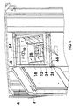
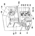
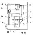
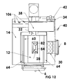
- FIGS. 6 through 12 depict additional details to the construction of the exhaust manifold 34 and several other air control and tertiary burner assemblies described below.
- Removable panels 42, 44 and 46 are mounted to the framework of the housing 4 at a rear wall 48 and permit access to the various burners, fans, pumps, baffles, servos, plumbing fittings and the like used to operate the stove/boiler 2.
- a further cover 50 permits access to the primary flue 6 for inspection and cleaning.
- the stove/boiler 2 is designed to operate with biomass fuels, however, a tertiary, gas or oil fired burner 52, such as disclosed at US patent no. 6,718,889 , is fitted to a conduit 54 at a rear wall of the primary burn chamber 12.
- the tertiary burner 52 is principally operated during cold starts until the stove 2 reaches operating temperatures.
- the burner 52 can be used as a primary heat source when wood or other biomass materials are unavailable or too costly or during periods when operating personnel aren't available to tend the stove/boiler 2.
- the 80% plus operating efficiencies of the stove/boiler 2 are obtained in part by injecting pressurized air into the primary and secondary burn chambers 12 and 30 and at the exhaust fire tubes 36.
- pressurized combustion air is injected into the primary bum chamber 12 via a hollow conduit assembly 60 that substantially circumscribes the primary burn chamber 12 and through which the conduit 54 passes.
- the assembly 60 includes horizontal segments 62 that circumscribe the rear and side walls of the primary bum chamber 12.
- the horizontal segments 62 are located at or below the vertical height of the primary burn chamber 12 to maintain the combustion air near the primary combustion zone for the particular combustion material.
- Primary combustion typically occurs in the lower third of a pile of combustible material or near the ash pile.
- Vertical segments 64 extend from the ends of the segments 62 and project parallel to the sides of the door 6.
- the assembly 60 is thus located slightly above the refractory floor 18 and below the midway point of the primary burn chamber 12 to promote combustion.
- Orifices 66 displaced along the segments 62 and 64 dispense pressurized combustion air conducted through the conduit assembly 60 into the primary burn chamber 12.
- the pressurized combustion air mixes with the combustion gases and smoke to produce turbulence and enhance the burning of hydrocarbons.
- the size and location of the orifices 66 are selected to optimize fuel combustion within the chamber 12.
- the primary combustion air admitted to the stove/boiler 2 exhibits a nominal positive pressure in the range of .1 to 1 inch of water column (WC) within the primary burn chamber 12.
- the positive pressure is obtained with primary and secondary combustion air fan assist assemblies discussed below. It is to be appreciated negatively pressurized stove/boiler 2 could be constructed to draw primary and secondary combustion air and exhaust gases through the assembly 2 with fan or other airflow assist assemblies.
- the pressurized air is supplied from an air manifold or plenum 66 mounted to the rear wall of the thermal transfer chamber 14.
- the chamber 14 is fed by a fan 68, reference Figures 8 through 11 .
- Air is directed from the plenum 66 into a conduit 70 that extends to the primary combustion air conduit assembly 60.
- An intermediate solenoid operated baffle 72 controls air flow into the conduit 70.
- Another conduit 74 and solenoid controlled baffle 72 direct pressurized combustion air into the secondary burner 28.
- a further conduit 76 and solenoid controlled baffle 72 direct pressurized combustion air into the secondary bum chamber 30.
- the conduit 76 can also cooperate with a gas or liquid fired burner (e.g. propane or natural gas or oil) similar to the burner 52 to support and enhance combustion in the secondary burn chamber 30.
- Microprocessor control circuitry at the controller 10 determines appropriate timing signals to control the on/off duty cycling of the baffles 72 and gas/oil fired burners 52.
- the ash port 24 is located at the approximate center of the refractory floor 18.
- the baffles 26 segregate the port 24 to receive and direct combustion gases and smoke into the secondary burn chamber 30.
- the baffles 26 segregate the port 24 to receive and direct combustion gases and smoke into the secondary burn chamber 30.
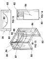
- the exhaust gases pass through an arcuate vertical channel 80 defined by an arcuate (e.g. semi-circular) front wall 82 of the secondary burner 28 and a rear wall 84 of the secondary bum chamber 30.
- Pressurized and preheated secondary combustion air is conducted via conduit 74 to the side wall of the secondary burner 28 and into a cavity 81 behind front wall 82.
- a portion of the pressurized air is diverted into right and left wing chambers 83 and 85 that depend from the sides of the burner 28 into the secondary burn chamber 30.
- Internal baffles 86 at the wing chambers 83 and 85 divert a portion of the secondary combustion air into the depending portions of the wing chambers 83 and 85.
- the disruption and partial bleeding of air flow into the wing chambers 83 and 85 induces turbulence in the cavity 81 and wing chambers 83 and 85.
- the turbulence and re-direction of air produces a delay in the air flow before the air is ejected from orifices 88 arranged over the arcuate burner wall 82.
- the delay facilitates the preheating of the secondary combustion air from the conduit 74 in the cavity 81 before being ejected into the channel 80 and secondary burn chamber 30, reference Figures 13, 14 and 15 .
- Thermal energy is also transferred to the depending portions of the wing chambers 83 and 85 that extend into the secondary burn chamber 30 to maintain combustion of hydro carbons in the exhaust gases in the secondary burn chamber 30.
- the secondary combustion air directed from the orifices 88 strikes and reflects the exhaust gases in the channel 80 between the walls 82 and 84.
- the turbulent flow optimizes the ignition and combustion of hydrocarbons and other combustibles in the exhaust gases that flow through the channel 80 and into the secondary burn/ash chamber 30.
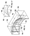
- FIGS 16 and 17 depict a first alternative secondary burner 90.
- the burner 90 provides an arcuate front wall 92 that also directs preheated pressurized secondary combustion air into exhaust gases directed into the channel 80 and secondary burn chamber 30.
- the wall 92 provides several panels 94 that each contain an orifice 96.
- the panels 94 are arranged to form a semi-circular arc of suitable radius. Secondary combustion air admitted into an interior cavity 95 of the burner 90 via the conduit 74 is delayed by baffles 96 and 98 with a consequent heating of the air before being ejected from the orifices 96.
- the burner 90 thus produces turbulent flow that optimizes the combustion of hydrocarbons and other combustibles in the gases.
- FIGS 18 and 19 depict a second alternative secondary burner 100.
- the burner 100 provides a semi-circular, corrugated front wall 102 that also directs preheated pressurized secondary combustion air into exhaust gases directed into the channel 80 into the secondary burn chamber 30.
- the wall 102 provides several grooved recesses 94 defined by opposed wall panels 106 that each contain an orifice 108.
- the panels 1066 generally project at 90° to each other.
- Secondary combustion air admitted to the interior of the burner 100 is delayed by a baffle 110 before being ejected from the orifices 108.
- the mixing of the combustion air with the exhaust gases passing through the channel 80 produces reflections between the rear wall 80 and between adjacent faces of the panels 102.
- the secondary burner 100 produces turbulent flow that optimizes the combustion of hydrocarbons and other combustibles in the exhaust gases admitted to the secondary burn/ash chamber 30. It is to be appreciated still other secondary burner configurations can be constructed to induce turbulence in the exhaust gases.
- Combustion continues in the secondary burn/ash chamber 30 upon subjecting the exhaust gases to additional pressurized and heated air supplied from the conduit 76.
- a fuel fired burner e.g. propane or natural gas or oil
- propane or natural gas or oil like the burner 52 can be fitted to the conduit 76 to sustain and enhance combustion in the secondary burn chamber 30.
- the secondary burn/ash chamber 30 is also lined with refractory materials to maintain secondary burn temperatures.
- the tubes 36 extend at an acute angle between the secondary burn chamber 30 and the exhaust manifold 34 mounted to rear wall of the thermal transfer chamber 14.
- the tubes 36 are spaced apart from and extend parallel to each other.
- the tubes 36 extend through the thermal transfer chamber 14 and the liquid flows around each tube 36.
- the number and spacing between the tubes 36 is selected to facilitate heat transfer from the heated exhaust gases to the liquid media contained in the thermal transfer chamber 14.
- the tubes 36 project from the secondary burn chamber 30 at an acute angle in the range of 40 to 70 degrees.
- the walls of the tubes 36 are shaped and formed to delay and promote turbulent flow through the fire tubes 36.
- the prolonged, turbulent flow enhances the burning of hydrocarbons contained in the exhaust gases, heat transfer and ultimately enhances efficiency of the stove/boiler 2.
- the walls of the exhaust/fire tubes 36 presently exhibit a parallelogram shaped, transverse cross-sectional profile.
- the wall geometry and transverse and longitudinal cross-sectional shapes of the exhaust/fire tubes 36 can be varied as desired to promote internal turbulence and heat transfer without requiring the mounting of a discrete turbulator assembly along the path of the exhaust gases.
- the walls can be configured in a variety of cross-sectional shapes and forms such as the depicted parallelogram shape or with square, star or other straight or curved wall section shapes.
- the tube walls may also be formed with grooves, fluting, projections, obstructions and/or V-shaped edges or corners.
- the wall surfaces can also be varied and/or interrupted with changed shapes or bends along their lengths.
- the fire tubes 36 can be formed straight as depicted or can include appropriate bends, twists and/or turns. Any ultimate tube shape and/or combination is desirably constructed to promote turbulence in the exhaust gases versus smooth cross-sectional shapes.
- the acute, angular alignment of the exhaust or fire tubes 36 is arranged to direct carbon deposits that flake from the walls of the exhaust tubes 36 back into the secondary burn/ash chamber 30. Carbon deposits in the tubes 36 can also be manually cleaned upon opening the access panel 42 at the exhaust manifold 34. As the tubes 36 and carbon deposits are scraped or brushed from the interior walls of the tubes 36, the deposits fall into the ash chamber 30 and are removed via the door 8.
- the space behind the rear covers 44 and 46 and in front of the insulation that covers the rear wall of the thermal transfer chamber 14 contains liquid supply and return fittings, liquid conduits 106, a liquid pump, fan blower 68, baffles 72, gas/oil burners 52, flame sensors, thermostat sensors, and sundry other stove servos, sensors and controls.
- the control devices communicate with programmed microprocessor circuitry at the controller 10 and variously supply and receive control signals.
- the sensors and switches monitor among different operating parameters, stack temperature, water temperature, flame conditions, oxygen levels, and door conditions.
- the microprocessor is programmed to control several general modes of operation.
- a "cold start” mode operates to supply gas to the tertiary gas/oil burner(s) 52 to provide heat to ignite the biomass pile.
- the tertiary burner(s) 52 are subsequently operated to optimize combustion efficiencies or during a "backup” mode if the stove temperature falls due to fuel depletion.
- the biomass burns and the stove/boiler 2 is controlled to maintain a thermostatically set temperature and appropriately direct combustion air flow via the blower 68 and baffles 72.
- the duty cycle or on/off times of the baffles 72 are appropriately controlled to maintain optimal bum conditions.
Landscapes
- Engineering & Computer Science (AREA)
- Mechanical Engineering (AREA)
- General Engineering & Computer Science (AREA)
- Chemical & Material Sciences (AREA)
- Combustion & Propulsion (AREA)
- Physics & Mathematics (AREA)
- Thermal Sciences (AREA)
- Environmental & Geological Engineering (AREA)
- Life Sciences & Earth Sciences (AREA)
- Sustainable Development (AREA)
- Sustainable Energy (AREA)
Applications Claiming Priority (2)
| Application Number | Priority Date | Filing Date | Title |
|---|---|---|---|
| US90689707P | 2007-03-13 | 2007-03-13 | |
| US12/075,530 US7954438B2 (en) | 2007-03-13 | 2008-03-12 | Wood fired boiler |
Publications (2)
| Publication Number | Publication Date |
|---|---|
| EP1983258A2 true EP1983258A2 (de) | 2008-10-22 |
| EP1983258A3 EP1983258A3 (de) | 2010-03-31 |
Family
ID=39473456
Family Applications (1)
| Application Number | Title | Priority Date | Filing Date |
|---|---|---|---|
| EP08250852A Withdrawn EP1983258A3 (de) | 2007-03-13 | 2008-03-13 | Mit Holz betriebener Kessel |
Country Status (1)
| Country | Link |
|---|---|
| EP (1) | EP1983258A3 (de) |
Cited By (1)
| Publication number | Priority date | Publication date | Assignee | Title |
|---|---|---|---|---|
| RU2670131C1 (ru) * | 2017-07-03 | 2018-10-18 | Вадим Сергеевич Рыжов | Отопительный котёл |
Citations (1)
| Publication number | Priority date | Publication date | Assignee | Title |
|---|---|---|---|---|
| US6718889B1 (en) | 2002-08-30 | 2004-04-13 | Central Boiler, Inc. | Draft controlled boiler fuel nozzle |
Family Cites Families (7)
| Publication number | Priority date | Publication date | Assignee | Title |
|---|---|---|---|---|
| DE3737661A1 (de) * | 1987-11-06 | 1989-05-24 | Karl Ackermann | Heizungskessel mit zwangsweiser zufuhr der verbrennungsluft |
| DE3742578A1 (de) * | 1987-12-16 | 1989-07-06 | Norbert Harlander | Brenner fuer feste brennstoffe |
| EP0409790A1 (de) * | 1989-07-19 | 1991-01-23 | Willi Hager | Feuerungsanlage |
| DE19531821A1 (de) * | 1995-08-15 | 1997-02-20 | Christian Dipl Ing Herlt | Vergaserheizkessel für feste Brennstoffe, insbesondere für Holz |
| DE19612045A1 (de) * | 1996-03-27 | 1997-10-02 | Hoval Interliz Ag | Heizkessel und Verfahren zu seinem Betreiben |
| DE19646525C1 (de) * | 1996-10-29 | 1998-06-10 | Christian Dipl Ing Herlt | Vergaserheizkessel für feste Brennstoffe, insbesondere für Holz |
| ATE408788T1 (de) * | 2004-02-19 | 2008-10-15 | Brevet 2000 Holding S A | Heizkessel mit flammeumkehrung |
-
2008
- 2008-03-13 EP EP08250852A patent/EP1983258A3/de not_active Withdrawn
Patent Citations (1)
| Publication number | Priority date | Publication date | Assignee | Title |
|---|---|---|---|---|
| US6718889B1 (en) | 2002-08-30 | 2004-04-13 | Central Boiler, Inc. | Draft controlled boiler fuel nozzle |
Cited By (1)
| Publication number | Priority date | Publication date | Assignee | Title |
|---|---|---|---|---|
| RU2670131C1 (ru) * | 2017-07-03 | 2018-10-18 | Вадим Сергеевич Рыжов | Отопительный котёл |
Also Published As
| Publication number | Publication date |
|---|---|
| EP1983258A3 (de) | 2010-03-31 |
Similar Documents
| Publication | Publication Date | Title |
|---|---|---|
| CA2625536C (en) | Wood fired boiler | |
| KR101524436B1 (ko) | 화목겸용 펠렛난로 | |
| US20080041357A1 (en) | Combustion Apparatus for Solid Fuel | |
| EP2884200B1 (de) | Zentralheizungskessel | |
| BG66233B1 (bg) | Отоплителен котел | |
| EP1821038A2 (de) | Öfen | |
| RU2660987C1 (ru) | Пиролизный котел-утилизатор | |
| RU2097660C1 (ru) | Печь конвекционная | |
| US20050284421A1 (en) | Coal combusting boiler | |
| RU2439437C1 (ru) | Газогенераторное отопительное устройство | |
| KR20110043564A (ko) | 단열된 수직연소로의 화목연소장치 와 열교환기 | |
| RU2661516C2 (ru) | Твердотопливный газогенераторный котёл | |
| RU2452905C2 (ru) | Котел водогрейный и способ его работы | |
| RU46335U1 (ru) | Печь отопительная | |
| RU2362093C1 (ru) | Водогрейный котел | |
| KR101325663B1 (ko) | 화목보일러용 연소구 | |
| RU2282790C2 (ru) | Печь отопительно-варочная | |
| RU2408822C1 (ru) | Печь, воздуховод и теплообменник для нее | |
| RU2331816C1 (ru) | Камин | |
| RU2485414C2 (ru) | Котел отопления, работающий на дровах | |
| RU2361154C1 (ru) | Способ передачи тепла | |
| EP1230521B1 (de) | Kessel mit verbrennungsretorte | |
| RU121041U1 (ru) | Котел отопительный | |
| GB2227084A (en) | Stove with afterburner | |
| RU98545U1 (ru) | Котел отопительный водогрейный с отбором горячей воды |
Legal Events
| Date | Code | Title | Description |
|---|---|---|---|
| PUAI | Public reference made under article 153(3) epc to a published international application that has entered the european phase |
Free format text: ORIGINAL CODE: 0009012 |
|
| AK | Designated contracting states |
Kind code of ref document: A2 Designated state(s): AT BE BG CH CY CZ DE DK EE ES FI FR GB GR HR HU IE IS IT LI LT LU LV MC MT NL NO PL PT RO SE SI SK TR |
|
| AX | Request for extension of the european patent |
Extension state: AL BA MK RS |
|
| PUAL | Search report despatched |
Free format text: ORIGINAL CODE: 0009013 |
|
| AK | Designated contracting states |
Kind code of ref document: A3 Designated state(s): AT BE BG CH CY CZ DE DK EE ES FI FR GB GR HR HU IE IS IT LI LT LU LV MC MT NL NO PL PT RO SE SI SK TR |
|
| AX | Request for extension of the european patent |
Extension state: AL BA MK RS |
|
| 17P | Request for examination filed |
Effective date: 20100927 |
|
| 17Q | First examination report despatched |
Effective date: 20101103 |
|
| AKX | Designation fees paid |
Designated state(s): AT BE BG CH CY CZ LI |
|
| RBV | Designated contracting states (corrected) |
Designated state(s): AT BE BG CH CY CZ DE DK EE ES FI FR GB GR HR HU IE IS IT LI LT LU LV MC MT NL NO PL PT RO SE SI SK TR |
|
| REG | Reference to a national code |
Ref country code: DE Ref legal event code: 8566 |
|
| GRAP | Despatch of communication of intention to grant a patent |
Free format text: ORIGINAL CODE: EPIDOSNIGR1 |
|
| STAA | Information on the status of an ep patent application or granted ep patent |
Free format text: STATUS: GRANT OF PATENT IS INTENDED |
|
| INTG | Intention to grant announced |
Effective date: 20170227 |
|
| STAA | Information on the status of an ep patent application or granted ep patent |
Free format text: STATUS: THE APPLICATION IS DEEMED TO BE WITHDRAWN |
|
| 18D | Application deemed to be withdrawn |
Effective date: 20170711 |