EP1983278A2 - Collecteur de fluide - Google Patents
Collecteur de fluide Download PDFInfo
- Publication number
- EP1983278A2 EP1983278A2 EP08005390A EP08005390A EP1983278A2 EP 1983278 A2 EP1983278 A2 EP 1983278A2 EP 08005390 A EP08005390 A EP 08005390A EP 08005390 A EP08005390 A EP 08005390A EP 1983278 A2 EP1983278 A2 EP 1983278A2
- Authority
- EP
- European Patent Office
- Prior art keywords
- fluid collector
- collector according
- container
- dryer housing
- guide
- Prior art date
- Legal status (The legal status is an assumption and is not a legal conclusion. Google has not performed a legal analysis and makes no representation as to the accuracy of the status listed.)
- Withdrawn
Links
- 239000012530 fluid Substances 0.000 title claims description 43
- 230000000087 stabilizing effect Effects 0.000 claims abstract 2
- 239000003507 refrigerant Substances 0.000 claims description 38
- 239000004744 fabric Substances 0.000 claims description 7
- 230000007704 transition Effects 0.000 claims description 5
- 238000011084 recovery Methods 0.000 claims 1
- 239000002826 coolant Substances 0.000 abstract 2
- 238000000926 separation method Methods 0.000 description 5
- 239000008187 granular material Substances 0.000 description 4
- 239000007788 liquid Substances 0.000 description 4
- 239000012535 impurity Substances 0.000 description 3
- 238000004519 manufacturing process Methods 0.000 description 3
- 239000002245 particle Substances 0.000 description 3
- 239000004033 plastic Substances 0.000 description 3
- 238000010521 absorption reaction Methods 0.000 description 2
- 238000010276 construction Methods 0.000 description 2
- 239000000356 contaminant Substances 0.000 description 2
- 238000001816 cooling Methods 0.000 description 2
- 238000013016 damping Methods 0.000 description 2
- 230000000694 effects Effects 0.000 description 2
- 238000007789 sealing Methods 0.000 description 2
- 239000000126 substance Substances 0.000 description 2
- 239000004952 Polyamide Substances 0.000 description 1
- 238000005299 abrasion Methods 0.000 description 1
- 238000004378 air conditioning Methods 0.000 description 1
- XAGFODPZIPBFFR-UHFFFAOYSA-N aluminium Chemical compound [Al] XAGFODPZIPBFFR-UHFFFAOYSA-N 0.000 description 1
- 229910052782 aluminium Inorganic materials 0.000 description 1
- 230000001914 calming effect Effects 0.000 description 1
- 238000005266 casting Methods 0.000 description 1
- 230000001419 dependent effect Effects 0.000 description 1
- 230000008021 deposition Effects 0.000 description 1
- 238000011161 development Methods 0.000 description 1
- 230000018109 developmental process Effects 0.000 description 1
- 238000006073 displacement reaction Methods 0.000 description 1
- 238000001746 injection moulding Methods 0.000 description 1
- 238000003780 insertion Methods 0.000 description 1
- 230000037431 insertion Effects 0.000 description 1
- 238000009434 installation Methods 0.000 description 1
- 239000007791 liquid phase Substances 0.000 description 1
- 239000003129 oil well Substances 0.000 description 1
- 238000005192 partition Methods 0.000 description 1
- 230000035515 penetration Effects 0.000 description 1
- 230000002093 peripheral effect Effects 0.000 description 1
- 229920002647 polyamide Polymers 0.000 description 1
- 229920000642 polymer Polymers 0.000 description 1
- 230000002265 prevention Effects 0.000 description 1
- 230000000284 resting effect Effects 0.000 description 1
- 229910000679 solder Inorganic materials 0.000 description 1
- 239000000243 solution Substances 0.000 description 1
- 230000006641 stabilisation Effects 0.000 description 1
- 238000011105 stabilization Methods 0.000 description 1
Images




Classifications
-
- F—MECHANICAL ENGINEERING; LIGHTING; HEATING; WEAPONS; BLASTING
- F25—REFRIGERATION OR COOLING; COMBINED HEATING AND REFRIGERATION SYSTEMS; HEAT PUMP SYSTEMS; MANUFACTURE OR STORAGE OF ICE; LIQUEFACTION SOLIDIFICATION OF GASES
- F25B—REFRIGERATION MACHINES, PLANTS OR SYSTEMS; COMBINED HEATING AND REFRIGERATION SYSTEMS; HEAT PUMP SYSTEMS
- F25B9/00—Compression machines, plants or systems, in which the refrigerant is air or other gas of low boiling point
- F25B9/002—Compression machines, plants or systems, in which the refrigerant is air or other gas of low boiling point characterised by the refrigerant
- F25B9/008—Compression machines, plants or systems, in which the refrigerant is air or other gas of low boiling point characterised by the refrigerant the refrigerant being carbon dioxide
-
- F—MECHANICAL ENGINEERING; LIGHTING; HEATING; WEAPONS; BLASTING
- F25—REFRIGERATION OR COOLING; COMBINED HEATING AND REFRIGERATION SYSTEMS; HEAT PUMP SYSTEMS; MANUFACTURE OR STORAGE OF ICE; LIQUEFACTION SOLIDIFICATION OF GASES
- F25B—REFRIGERATION MACHINES, PLANTS OR SYSTEMS; COMBINED HEATING AND REFRIGERATION SYSTEMS; HEAT PUMP SYSTEMS
- F25B43/00—Arrangements for separating or purifying gases or liquids; Arrangements for vaporising the residuum of liquid refrigerant, e.g. by heat
- F25B43/006—Accumulators
-
- F—MECHANICAL ENGINEERING; LIGHTING; HEATING; WEAPONS; BLASTING
- F25—REFRIGERATION OR COOLING; COMBINED HEATING AND REFRIGERATION SYSTEMS; HEAT PUMP SYSTEMS; MANUFACTURE OR STORAGE OF ICE; LIQUEFACTION SOLIDIFICATION OF GASES
- F25B—REFRIGERATION MACHINES, PLANTS OR SYSTEMS; COMBINED HEATING AND REFRIGERATION SYSTEMS; HEAT PUMP SYSTEMS
- F25B2309/00—Gas cycle refrigeration machines
- F25B2309/06—Compression machines, plants or systems characterised by the refrigerant being carbon dioxide
- F25B2309/061—Compression machines, plants or systems characterised by the refrigerant being carbon dioxide with cycle highest pressure above the supercritical pressure
-
- F—MECHANICAL ENGINEERING; LIGHTING; HEATING; WEAPONS; BLASTING
- F25—REFRIGERATION OR COOLING; COMBINED HEATING AND REFRIGERATION SYSTEMS; HEAT PUMP SYSTEMS; MANUFACTURE OR STORAGE OF ICE; LIQUEFACTION SOLIDIFICATION OF GASES
- F25B—REFRIGERATION MACHINES, PLANTS OR SYSTEMS; COMBINED HEATING AND REFRIGERATION SYSTEMS; HEAT PUMP SYSTEMS
- F25B43/00—Arrangements for separating or purifying gases or liquids; Arrangements for vaporising the residuum of liquid refrigerant, e.g. by heat
- F25B43/003—Filters
Definitions
- the present invention relates to a fluid collector, in particular for refrigerant in a supercritical working refrigerant circuit, with a gas-tight container, a U-shaped intake manifold, a dryer, a gas filter which covers the open end of the suction tube, and a guide which the Kältescheinström Suite separates from the calmed collection area.
- Such a fluid collector is for example from the EP 1 564 510 known.
- upper tank area is formed as a cyclone chamber.
- the vertically extending, tubular inlet channel has a peripheral opening which is provided on a circumferential area directed tangentially to the inner surface of the container. Such an arrangement results in a rotational flow running along the inner surface of the container.
- the open end of the suction tube, through which the refrigerant leaves the collector with a vapor content that is as constant as possible, is arranged centrally above the horizontal dividing wall, in the center of the cyclone chamber.
- the inflow pipe must be firmly connected to the container lid in such a solution in which it is not supported within the container.
- the inflow channel is an obliquely outwardly and tangentially to the inner surface extending bore in the upper container area educated.
- the suction tube of this second embodiment has an inner tube and an outer tube coaxial therewith, which extend along the container axis into the bottom region.
- this suction tube arrangement which has a large length-to-diameter ratio and thus tends to oscillate, is supported by three radially extending ribs on the inner surface of the collecting container. Excessive vibration of the devices located in the reservoir leads in addition to disturbing noises also to turbulence of the refrigerant in the collector, whereby a reassurance of the collector contents is disturbed.
- the vapor content of the refrigerant, which is sucked in from the suction tube end in the central region of the cyclone chamber, depends inter alia on the degree of saturation of the currently entering medium and on the resulting cyclone flow.
- a defined, uniform vapor content and a safe separation of substances in the inflowing medium such as oil, solder residues and metallic impurities is not guaranteed.
- refrigerant collector for example, have guide devices such as baffles on which the incoming refrigerant impinges.
- the known arrangements protect the collected, liquid refrigerant from re-whirling, but support only limited the deposition of gaseous and liquid refrigerant or oil or a separation of Lotresten etc.
- a constant outlet steam content depending on the volume of the liquid refrigerant in the collector arises only conditionally. Filter surfaces which are intended to retain undissolved particles are usually provided only for the oil aspirated by the suction tube.
- the object of the present invention is therefore to provide an improved fluid collector which can be designed simply and safely, reduces acoustic disturbances, allows a substantially constant outlet steam content and promotes the separation of foreign substances present in the refrigerant.
- a fluid collector according to the invention comprises a conventional collecting container with a lid, which ensures the inflow and outflow of the refrigerant used and preferably closes the container gas-tight.
- the discharge line of a preferably U-shaped suction tube is preferably guided by the lid of the collecting container to the outside.
- the second end of the suction pipe, which sucks the refrigerant from the collector with the most constant possible vapor content, preferably ends in the calmed collecting area.
- This end of the suction tube is preferably shielded by a gas filter which prevents contaminants from the collection area from entering the suction line.
- At least one opening for the return of settling on the container bottom oil is provided in the region of the deflection of the U-shaped suction pipe.
- This perforated region of the suction tube is preferably shielded by an oil filter, which prevents suction of possibly also deposited on the container bottom impurities in the cooling circuit.
- a dryer housing which preferably receives the dryer granules, connected.
- the dryer - consisting of dryer housing and dryer granulate - according to the invention is not forced through, thereby becoming almost no additional pressure drop within the collector results. This minimizes negative effects on the flow behavior.
- the connection between the oil filter and dryer housing which are both preferably made of plastic, can be made for example by at least one clip connection.
- the dryer housing preferably has a cylindrical shape whose diameter is preferably less than or equal to the distance between the two axes of the U-shaped suction pipe extending parallel to the dryer housing axis.
- the elements of the interior of the fluid collector are preferably made of plastic.
- the term "interior” preferably includes the suction tube with oil filter, the dryer housing attached thereto and arranged at the end of the suction pipe gas filter and the associated guide. To connect these components, the use of clip connections has proven to be particularly advantageous. It should be noted, however, that in the context of this invention, despite the clip connections described, all other suitable possibilities for connecting various components should also be included.
- Both the oil filter and the dryer housing are preferably produced by plastic injection molding, wherein the mesh fabric, which preferably has a mesh size between 20 .mu.m and 150 .mu.m, is firmly connected to the structural elements during the casting process.
- a first support device is arranged according to the invention, which is preferably arranged around the dryer housing oil filter connection and also protects it.
- the main task of the support means is to prevent vibrations of the interior of the fluid collector.
- the support device preferably comprises a first support device and a second support device.
- a first support device preferably supports the interior device on the inner wall of the container.
- possible vibrations of the U-tube are preferably damped in the vertical and horizontal directions.
- results from such a support increased resistance to small displacements of the interior relative to the container, so-called "bucking", whereby a, required in known arrangements, attachment of the suction tube on the lid can be omitted.
- this first support means is at least partially elastically mounted on the inner wall, whereby a significant damping of vibrations is achieved.
- the first support device is arranged at least partially between the oil filter and the dryer housing.
- a first support means may also be arranged above the connection between the oil filter and the dryer housing on the intake manifold.
- this first support means is at least partially disc-shaped.
- the support takes place at a maximum circumferential region of the container wall, whereby an optimal force absorption in the horizontal plane takes place and the tendency of the interior of the interior to be minimized in the container.
- the first support means as a support disk, a plurality of through holes for the refrigerant is provided. Due to the passage of the refrigerant into the region below the support means, a further calming of the liquid refrigerant and the settling oil takes place.
- the first support device is arranged in the transition region to the container bottom.
- the container wall preferably has at least one horizontally projecting element, such as a shoulder, on which a first support device can be positively supported in the vertical direction.
- the oil filter according to the invention which encloses the U-shaped suction tube in the region of the deflection, is preferably constructed of two identical, mutually connectable halves.
- the construction of the oil filter from two identical halves allows, since the production can be done with a tool, a significant reduction in manufacturing costs.
- the two halves connected by clip connections comprise the suction tube so that no contaminants can enter the opening for returning collected oil.
- the shape of the passages for the suction pipe is adapted to its cross-section. In case of increased sealing requirements, a soft component can be incorporated in the sealing plane of the two halves.
- a preferably arranged on the trapezoidal oil filter lower crossbar preferably sits in the oil well of the container.
- the transverse web has a slope for insertion into a particle pan.
- the oil filter is advantageously designed so that this crosspiece supports the interior of the fluid collector on the container bottom.
- this lower crosspiece assumes the function of a second support means.
- the weight of the interior is supported by the oil filter on the container bottom, whereby vertical forces of the Interior be initiated directly into the container bottom.
- the execution of the discharge line through the collector cover simplifies.
- a round bolt is arranged on the crossbar of the oil filter, which engages in a blind hole arranged in the collector bottom and serves as a positional fixation of the interior of the fluid collector.
- the dryer housing is arranged at the top of the oil filter, between the two ends of the U-shaped suction tube.
- clip connections are preferably provided which comprise the outer diameter of the suction tube.
- fasteners may be attached to several suitable locations of the dryer housing, however, to achieve a rigid connection as possible, it is preferable to arrange such elements once in the lower region of the dryer housing and once in its upper region.
- the lower portion of the dryer housing preferably has no filter cloth to absorb the abrasion caused by relative movement between the dryer granules.
- the gas filter which shields the open end of the suction tube, is preferably used to prevent the penetration of fluidized dirt particles into the suction channel.
- the suction opening is preferably at the highest possible point in the collector.
- the gas filter on a flow-stabilized location is to prevent a short circuit between the refrigerant flowing into the collector and the refrigerant leaving the fluid collector via the gas filter.
- a guide device is arranged on the upper side of the gas filter which separates the refrigerant inflow region from the collecting region.
- the connection between gas filter and guide is also preferably made by means of clip connections. Due to a preferred connection of Saugrohrende, gas filter and guide additional stabilization of the interior takes place. It is likewise preferred if the suction pipe, the gas filter and the guide device are also connected to the dryer housing.
- a sleeve-shaped gas filter which is arranged in the end region of the suction tube, closed at the top by the guide of the fluid collector.
- this guide separates the Kälfieffeneinström Scheme from the collector area.
- at least one stop element is provided on the underside of this guide, which defines the distance between the end of the suction tube and the underside of the guide. This defined distance range is preferably enclosed by the gas filter.
- the at least one stop element which ensures the connection between the collecting container and discharge line, prevents slippage of the guide and thus closing the Saugrohrqueritess.
- the diameter of the guide corresponds approximately to the inner diameter of the container of the fluid collector.
- the guide device is preferably designed so that a defined refrigerant passage area is created. The refrigerant then preferably flows in the farthest point to the gas filter in the lower collection area.
- the inlet of the refrigerant into the fluid collector takes place through a bore with a constant cross-section or, more preferably, through a bore with a nozzle-shaped cross-section.
- the refrigerant is on a guide directed, wherein the narrowest cross-section of the nozzle-shaped extending cross section should be 0.5 to 0.9 of the free intake pipe opening.
- the fluid collector according to the invention reduces the tendency of the fluid collector or the integrated intake manifold to oscillate even at high construction heights of the intake manifold, which increases the strength of the fluid collector and significantly improves the acoustic behavior. Furthermore, the design according to the invention assists a calmed introduction of the refrigerant in the fluid collector and thus improves the vapor content and the oil content of the extracted refrigerant. This also increases the life of the fluid collector. In addition, the fluid collector according to the invention can be adapted well to existing installation conditions.
- FIG. 1 an exemplary embodiment of a fluid collector according to the invention shown, consisting of a container 1 and a lid 2, in which openings are provided which allow the inflow and outflow of the refrigerant and which ensures a gas-tight closure of the container 1.
- the outlet line of the U-shaped suction tube 3 passes through the lid 2 and the second end, which is open to the interior of the collector, is shielded by a gas filter 8.
- the U-shaped intake manifold 3 has in the region of the deflection on a protected by an oil filter 4 opening (not shown), which serves for the return of settling at the collector bottom oil into the cooling circuit of the air conditioning.
- a dryer housing 6 is arranged at the top of the oil filter 4.
- a first support means is arranged, which is designed in the embodiment as a support disk 7.
- the support disk 7 further comprises both portions of the U-shaped suction tube 3, which are supported by means of the support disk 7 on the container wall.
- the gas filter 8, which shields the open end of the suction tube 3 is covered at its upper end by the guide 9, with which it is connected by means of a clip connection.
- the guide 9 separates the refrigerant inflow area from the calmed collecting area. The design of the inflow is essential for a very constant vapor content of the sucked refrigerant responsible.
- the suction pipe 3 of the exemplary embodiment is made of aluminum. All other components of the fluid collector are made of a CO 2 -resistant polymer, such as polyamide.
- the mesh fabric of the filter which is tightly connected to the filter structure during manufacture, has a mesh size of between 20 ⁇ m to 150 ⁇ m.
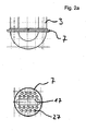
- Fig. 2a shows the support disk 7 arranged in front view of the suction pipe 3 and in a plan view.
- the edge of the support disk 7 is designed for an arrangement in the transition region to the container bottom.
- a recess 17 for receiving the suction pipe and connecting elements between the oil filter 4 and dryer housing 6 is shown.
- the support disk has a plurality of through holes 27 for the refrigerant.
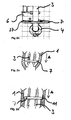
- Fig. 2b shows the arrangement of the support plate 7 between the oil filter 4 and dryer housing 6 in their function as additional assurance of the connection of Oil filter 4 and dryer housing 6.
- An encompassing clip connection 37 makes this additional backup.
- Fig. 2c the support disk 7 is shown in the transition region of a cylindrical wall of the container 1 to the domed bottom.
- the illustrated arrow A indicates the additional absorption of forces in the vertical direction through the container wall.
- Fig. 2d shows another example of the introduction of vertical forces in the container wall.
- the support disk 7 is here on a paragraph 11 in the container inner wall.
- Fig. 3a shows one half of an exemplary trapezoidal oil filter 4, which is composed of two identical, tightly connectable halves.
- the filter halves comprise the suction tube 3 so that no impurities can get into the oil hole.
- the exemplary oil filter 4 is firmly closed in the assembled state, wherein a mesh fabric is provided between the structural elements.
- the lower transverse web 14 is designed so that it serves to introduce vertical forces into the container bottom.
- Fig. 3b shows the connecting portion of the oil filter 4 with the dryer housing 6.
- the dryer housing 6 is connected via a connecting device 16 of the oil filter 4 with this.
- the connecting device 16 in this exemplary embodiment comprises a receiving surface 18 for the support disk 7.
- the width of the recess 17 of the support disk 7 is selected so that it locks the two nose halves 38 of the connecting device 16 and the holding device at the bottom of the dryer housing 6. A loosening is not possible.
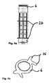
- Fig. 4a shows the dryer housing 6, which receives in its interior a dryer granules (not shown).
- the dryer housing 6 shown has a filter fabric between its structural components.
- snap elements 26 are arranged, which comprise the two legs 3a and 3b of the suction tube 3. The two legs are slightly offset under horizontal tension, so that the dryer housing 6 can not be torn from the anchor which form the snap elements 26.
- the dryer housing 6 thus forms a unit with the suction tube 3.
- the snap elements 26 are mounted in the embodiment shown by way of example once in the lower region of the dryer housing 6 and the other above the center of the dryer housing 6.
- Figure 4b schematically shows the cross section of the dryer housing 6 in the region of the snap elements 26th
- Fig. 5a shows an exemplary arrangement of the guide 9 at the upper end of the suction pipe 3.
- stop members 19 are arranged, which define a distance between Saugrohrende 3 and 9 guide. Slippage of the guide 9 with an associated reduction of the free cross section is not possible.
- the lid of the gas filter is at the same time surface of the guide 9.
- the horizontal extent of the guide 9 transversely to the container axis corresponds approximately to the inner housing of the container 1.
- the guide 9 is designed so that a defined refrigerant passage area is created.
- FIGS 5b to 5l Various exemplary embodiments of the guide 9 are shown.
- Fig. 5b shows the execution of an annular or crescent-shaped opening with an opening angle between 30 ° and 180 ° and an area opening ratio of 5 to 10% of the total area of the cross section of the guide 9th
- Fig. 5c shows over the entire circumference distributed recesses 29, which may be mounted, for example, only on the circumference of a circle segment.
- Fig. 5d shows a guide 9, whose passage opening is provided with a skirt 30 whose guide surface has an angle of 15 ° to 90 ° to the surface of the guide 9 and whose height is between 5 to 25 mm. Further, a circumferential edge 33 is provided on this guide 9, which prevents outflow of the refrigerant outside the skirt 30.
- Fig. 5e shows a guide 9 in shell form, which forms with the inner wall of the container 1 a thread-shaped, downwardly extending channel.
- the channel may extend in an angular range of 90 ° to 270 ° angle degree.
- the refrigerant is imparted a swirl directed downwards and towards the wall.
- the opening angle to the plane is approximately between 5 ° to 20 ° and the opening area about 5% to 10% of the total area of the guide 9th
- FIGS. 5f to 5l show various embodiments of the guide 9 with a threaded angle of also 90 ° to 270 °, a fixed opening angle to the plane of 5 ° to 20 ° and an opening area of 5 to 10% of the total area of the guide.
- FIGS. 5f to 5i various embodiments of the guide 9 in one-piece slide form
- Fig. 5j a guide 9 of two interlocking half-shells
- the Figures 5k and 5l show such a guide 9 of three pressed or welded plates.
Landscapes
- Engineering & Computer Science (AREA)
- Chemical & Material Sciences (AREA)
- Physics & Mathematics (AREA)
- Mechanical Engineering (AREA)
- Thermal Sciences (AREA)
- General Engineering & Computer Science (AREA)
- Chemical Kinetics & Catalysis (AREA)
- Analytical Chemistry (AREA)
- Power Engineering (AREA)
- Filtering Of Dispersed Particles In Gases (AREA)
Applications Claiming Priority (1)
| Application Number | Priority Date | Filing Date | Title |
|---|---|---|---|
| DE102007018427A DE102007018427A1 (de) | 2007-04-17 | 2007-04-17 | Fluidsammler |
Publications (2)
| Publication Number | Publication Date |
|---|---|
| EP1983278A2 true EP1983278A2 (fr) | 2008-10-22 |
| EP1983278A3 EP1983278A3 (fr) | 2010-01-13 |
Family
ID=39469545
Family Applications (1)
| Application Number | Title | Priority Date | Filing Date |
|---|---|---|---|
| EP08005390A Withdrawn EP1983278A3 (fr) | 2007-04-17 | 2008-03-20 | Collecteur de fluide |
Country Status (2)
| Country | Link |
|---|---|
| EP (1) | EP1983278A3 (fr) |
| DE (1) | DE102007018427A1 (fr) |
Cited By (1)
| Publication number | Priority date | Publication date | Assignee | Title |
|---|---|---|---|---|
| EP3062043A3 (fr) * | 2015-02-27 | 2017-03-01 | Mahle International GmbH | Séchoir |
Citations (1)
| Publication number | Priority date | Publication date | Assignee | Title |
|---|---|---|---|---|
| EP1564510A2 (fr) | 2004-02-17 | 2005-08-17 | Obrist Engineering GmbH | Collecteur pour la phase liquide d'un fluide de travail d'un conditionneur d'air |
Family Cites Families (9)
| Publication number | Priority date | Publication date | Assignee | Title |
|---|---|---|---|---|
| US5651266A (en) * | 1996-04-04 | 1997-07-29 | Eaton Corporation | Drier/accumulator for refrigerant system and method of making same |
| US6062039A (en) * | 1998-01-07 | 2000-05-16 | Parker-Hannifin Corporation | Universal accumulator for automobile air conditioning systems |
| DE19916674C2 (de) * | 1999-04-14 | 2002-02-07 | Hansa Metallwerke Ag | Akkumulator für eine nach dem "Orifice"-Prinzip arbeitende Klimaanlage, insbesondere Fahrzeugklimaanlage |
| DE20004328U1 (de) * | 2000-03-08 | 2000-05-18 | Hansa Metallwerke Ag, 70567 Stuttgart | Akkumulator für eine nach dem Orifice-Prinzip arbeitende Klimaanlage, insbesondere Fahrzeugklimaanlage |
| DE10037277C1 (de) * | 2000-07-28 | 2001-09-13 | Hansa Metallwerke Ag | Akkumulator für eine nach dem Orifice-Prinzip arbeitende Klimaanlage, insbesondere Fahrzeugklimaanlage |
| ITMI20010655U1 (it) * | 2001-12-14 | 2003-06-16 | Ti Automotive Cisliano S R L | Accumulatore disidratatore per circuiti di refrigerazione a strutturasemplificata |
| DE102004032279B3 (de) * | 2004-07-02 | 2005-08-18 | Hansa Metallwerke Ag | Akkumulator für eine Klimaanlage, insbesondere Fahrzeug-Klimaanlage |
| EP1696189B1 (fr) * | 2005-02-25 | 2017-09-27 | LG Electronics, Inc. | Conditionneur d'air avec plusieurs compresseurs |
| JP2006266524A (ja) * | 2005-03-22 | 2006-10-05 | Denso Corp | アキュムレータ |
-
2007
- 2007-04-17 DE DE102007018427A patent/DE102007018427A1/de not_active Withdrawn
-
2008
- 2008-03-20 EP EP08005390A patent/EP1983278A3/fr not_active Withdrawn
Patent Citations (1)
| Publication number | Priority date | Publication date | Assignee | Title |
|---|---|---|---|---|
| EP1564510A2 (fr) | 2004-02-17 | 2005-08-17 | Obrist Engineering GmbH | Collecteur pour la phase liquide d'un fluide de travail d'un conditionneur d'air |
Cited By (1)
| Publication number | Priority date | Publication date | Assignee | Title |
|---|---|---|---|---|
| EP3062043A3 (fr) * | 2015-02-27 | 2017-03-01 | Mahle International GmbH | Séchoir |
Also Published As
| Publication number | Publication date |
|---|---|
| DE102007018427A1 (de) | 2008-10-23 |
| EP1983278A3 (fr) | 2010-01-13 |
Similar Documents
| Publication | Publication Date | Title |
|---|---|---|
| DE102013017667B4 (de) | Filterelement mit einem Bypasskanal sowie Filteranordnung mit einem Filterelement | |
| DE68917888T2 (de) | Ölfilter. | |
| EP2145099B1 (fr) | Dispositif d'amenée de carburant destiné en particulier à un moteur à combustion interne | |
| EP2649292B1 (fr) | Filtre à carburant | |
| DE102005059014B4 (de) | Ölabscheider für einen Verbrennungsmotor | |
| DE102013012918B4 (de) | Flüssigkeitsfilter und Filterelement, insbesondere für Kraftstoff | |
| DE102010063822A1 (de) | Flüssigkeitsfilter mit einem Filterumgehungsventil | |
| EP2579958B1 (fr) | Dispositif de filtration, en particulier filtre pour liquides | |
| DE68917910T2 (de) | Ölfilter. | |
| DE102006038700B4 (de) | Vorrichtung zur Abscheidung von Flüssigkeiten aus Gasen | |
| EP1685784B1 (fr) | Dispositif d'aspiration | |
| EP1983278A2 (fr) | Collecteur de fluide | |
| EP1437563A2 (fr) | Accumulateur pour un appareil de climatisation, en particulier pour un appareil de climatisation de véhicule | |
| EP1917086B1 (fr) | Ensemble filtre a huile | |
| DE102005036580C5 (de) | Geruchverschluß mit Wechselpatrone | |
| DE69307787T2 (de) | Luftfilter mit niedrigem inneren Druckverlust | |
| DE102010009722A1 (de) | Ölnebelabscheider mit wenigstens einem Zyklon | |
| DE202009001159U1 (de) | Ölabscheider | |
| DE10158409C1 (de) | Akkumulator für eine Klimaanlage, insbesondere Fahrzeugklimaanlage | |
| DE102009006863A1 (de) | Ölabscheider | |
| DE102010027785B4 (de) | Ölnebelabscheider mit einem Gehäuse mit abnehmbarem Deckel | |
| EP2098657A2 (fr) | Dispositif d'écoulement des eaux d'une toiture | |
| EP1437562A2 (fr) | Accumulateur pour un appareil de climatisation, en particulier pour un appareil de climatisation de véhicule | |
| DE10307691A1 (de) | Filteranordnung für einen Verbrennungsmotor | |
| DE102008037904B4 (de) | Akkumulator |
Legal Events
| Date | Code | Title | Description |
|---|---|---|---|
| PUAI | Public reference made under article 153(3) epc to a published international application that has entered the european phase |
Free format text: ORIGINAL CODE: 0009012 |
|
| AK | Designated contracting states |
Kind code of ref document: A2 Designated state(s): AT BE BG CH CY CZ DE DK EE ES FI FR GB GR HR HU IE IS IT LI LT LU LV MC MT NL NO PL PT RO SE SI SK TR |
|
| AX | Request for extension of the european patent |
Extension state: AL BA MK RS |
|
| PUAL | Search report despatched |
Free format text: ORIGINAL CODE: 0009013 |
|
| AK | Designated contracting states |
Kind code of ref document: A3 Designated state(s): AT BE BG CH CY CZ DE DK EE ES FI FR GB GR HR HU IE IS IT LI LT LU LV MC MT NL NO PL PT RO SE SI SK TR |
|
| AX | Request for extension of the european patent |
Extension state: AL BA MK RS |
|
| AKY | No designation fees paid | ||
| STAA | Information on the status of an ep patent application or granted ep patent |
Free format text: STATUS: THE APPLICATION IS DEEMED TO BE WITHDRAWN |
|
| 18D | Application deemed to be withdrawn |
Effective date: 20100714 |
|
| REG | Reference to a national code |
Ref country code: DE Ref legal event code: 8566 |