EP1983304A2 - Kursstabilisierung für unterstützte Trägheitsnavigationssysteme - Google Patents
Kursstabilisierung für unterstützte Trägheitsnavigationssysteme Download PDFInfo
- Publication number
- EP1983304A2 EP1983304A2 EP08103532.1A EP08103532A EP1983304A2 EP 1983304 A2 EP1983304 A2 EP 1983304A2 EP 08103532 A EP08103532 A EP 08103532A EP 1983304 A2 EP1983304 A2 EP 1983304A2
- Authority
- EP
- European Patent Office
- Prior art keywords
- horizontal
- measurement unit
- inertial measurement
- axis
- orientation
- Prior art date
- Legal status (The legal status is an assumption and is not a legal conclusion. Google has not performed a legal analysis and makes no representation as to the accuracy of the status listed.)
- Granted
Links
Images


Classifications
-
- G—PHYSICS
- G01—MEASURING; TESTING
- G01C—MEASURING DISTANCES, LEVELS OR BEARINGS; SURVEYING; NAVIGATION; GYROSCOPIC INSTRUMENTS; PHOTOGRAMMETRY OR VIDEOGRAMMETRY
- G01C21/00—Navigation; Navigational instruments not provided for in groups G01C1/00 - G01C19/00
- G01C21/10—Navigation; Navigational instruments not provided for in groups G01C1/00 - G01C19/00 by using measurements of speed or acceleration
- G01C21/12—Navigation; Navigational instruments not provided for in groups G01C1/00 - G01C19/00 by using measurements of speed or acceleration executed aboard the object being navigated; Dead reckoning
- G01C21/16—Navigation; Navigational instruments not provided for in groups G01C1/00 - G01C19/00 by using measurements of speed or acceleration executed aboard the object being navigated; Dead reckoning by integrating acceleration or speed, i.e. inertial navigation
- G01C21/183—Compensation of inertial measurements, e.g. for temperature effects
- G01C21/188—Compensation of inertial measurements, e.g. for temperature effects for accumulated errors, e.g. by coupling inertial systems with absolute positioning systems
-
- G—PHYSICS
- G01—MEASURING; TESTING
- G01C—MEASURING DISTANCES, LEVELS OR BEARINGS; SURVEYING; NAVIGATION; GYROSCOPIC INSTRUMENTS; PHOTOGRAMMETRY OR VIDEOGRAMMETRY
- G01C21/00—Navigation; Navigational instruments not provided for in groups G01C1/00 - G01C19/00
- G01C21/10—Navigation; Navigational instruments not provided for in groups G01C1/00 - G01C19/00 by using measurements of speed or acceleration
- G01C21/12—Navigation; Navigational instruments not provided for in groups G01C1/00 - G01C19/00 by using measurements of speed or acceleration executed aboard the object being navigated; Dead reckoning
- G01C21/16—Navigation; Navigational instruments not provided for in groups G01C1/00 - G01C19/00 by using measurements of speed or acceleration executed aboard the object being navigated; Dead reckoning by integrating acceleration or speed, i.e. inertial navigation
- G01C21/165—Navigation; Navigational instruments not provided for in groups G01C1/00 - G01C19/00 by using measurements of speed or acceleration executed aboard the object being navigated; Dead reckoning by integrating acceleration or speed, i.e. inertial navigation combined with non-inertial navigation instruments
- G01C21/1652—Navigation; Navigational instruments not provided for in groups G01C1/00 - G01C19/00 by using measurements of speed or acceleration executed aboard the object being navigated; Dead reckoning by integrating acceleration or speed, i.e. inertial navigation combined with non-inertial navigation instruments with ranging devices, e.g. LIDAR or RADAR
-
- G—PHYSICS
- G01—MEASURING; TESTING
- G01C—MEASURING DISTANCES, LEVELS OR BEARINGS; SURVEYING; NAVIGATION; GYROSCOPIC INSTRUMENTS; PHOTOGRAMMETRY OR VIDEOGRAMMETRY
- G01C25/00—Manufacturing, calibrating, cleaning, or repairing instruments or devices referred to in the other groups of this subclass
- G01C25/005—Manufacturing, calibrating, cleaning, or repairing instruments or devices referred to in the other groups of this subclass initial alignment, calibration or starting-up of inertial devices
Definitions
- Inexpensive inertial navigation systems that are aided by only platform relative horizontal position change or velocity references may not undergo appropriate motions to observe heading drift rate.
- a gyroscope in a navigation system of an airborne vehicle is oriented to be sensitive to an axis that is perpendicular to a plane, which is tangential to the point on the earth directly below the gyroscope, and if the altitude of the airborne vehicle is not significantly varying, the heading drift of the gyroscope cannot be corrected by the filters in the inertial navigation system. Over time, the heading drift of the gyroscope results in large position errors in the inertial navigation system. This heading drift can cause the airborne vehicle to go off course.
- the present application discloses a method of stabilizing heading in an inertial navigation system.
- the method includes the operating an inertial measurement unit comprising horizontal-sensing elements and off-horizontal-sensing elements while the inertial measurement unit is in a first orientation, calibrating the horizontal-sensing elements of the inertial measurement unit based on horizontal aiding measurements, forward-rotating the inertial measurement unit by a selected-rotation angle about a horizontal-rotation axis so that the inertial measurement unit is oriented in a second orientation, operating the forward-rotated inertial measurement unit while the inertial measurement unit is in the second orientation, and calibrating the rotated off-horizontal-sensing elements based on horizontal aiding measurements while the inertial measurement unit is in the second orientation.
- the horizontal-sensing elements are oriented in a horizontal reference plane.
- the off-horizontal-sensing elements are oriented in the horizontal reference plane.
- FIG. 1 is a block diagram representative of an inertial navigation system 100 in accordance with the present invention.
- the inertial navigation system 100 shown in a vehicle 105 is an aided inertial navigation system 100 and functions to provide navigation solutions 280 to an external system 30.
- the inertial navigation system 100 includes an inertial measurement unit (IMU) 110, a rotational device 200, one or more sensors 130, a navigation processor 250, software module 300 stored or otherwise embodied in or on a storage medium 215, and a buffer 217 stored in a memory 235.
- the inertial measurement unit 110 is a sensor that is shown separately from the sensors 130 to clearly indicate the position of the inertial measurement unit 110 on the rotational device 200.
- the inertial measurement unit 110 outputs data (for example, in analog or digital form) that is indicative of one or more physical attributes associated with the inertial navigation system 100.
- the rotational device 200 is configured to rotate the inertial measurement unit 110 about a horizontal axis x 1 from a first orientation 170 to a second orientation 175 (shown in dashed lines).
- a horizontal reference plane is spanned by the axes (x 1 , y 1 ).
- the vehicle 105 travels substantially in the horizontal reference plane (x 1 , y 1 ).
- the vehicle 105 can be an airborne vehicle, a land-based vehicle, a water-based vehicle, or an under-water vehicle.
- the software module 300 includes a navigation module 310, Kalman filter 320, sensor compensator 305, and software control component 330.
- the navigation module 310 is configured to receive input from the inertial measurement unit 110.
- the Kalman filter 320 is communicatively coupled to receive input from the navigation module 310 and the sensors 130 and to send error-correction data to the navigation module 310 and to the sensor compensator 305.
- the software control component 330 is configured to control the rotation of the rotational device 200 based on input received from the Kalman filter 320.
- the Kalman filter 320 is replaced by another filter such as a Weiner filter.
- the sensors 130 include at least one of a horizontal velocity sensor 148 and a horizontal position sensor 142 that are operable to measure a horizontal velocity and a horizontal position, respectively, of the vehicle 105.
- the sensors 130 can also include other sensors 147 such as a GPS receiver, an odometer, Doppler radar, or Doppler sonar.
- the horizontal velocity sensor 148 and the horizontal position sensor 142 are aiding sensors that output the information indicative of a horizontal velocity and a horizontal position, respectively, to the Kalman filter 320. In one implementation of this embodiment, only one of the horizontal velocity reference and the horizontal position reference is provided to the Kalman filter 320.
- the Kalman filter 320 does a calibration (also referred to herein as "an alignment") of the inertial measurement unit 110 to compensate for detected errors in the inertial measurement unit 110.
- the calibration is done periodically, while the inertial measurement unit 110 is in the first orientation 170 and then while the inertial measurement unit 110 is in the second orientation 175.
- the Kalman filter 320 estimates a bias of the inertial measurement unit 110 and sends the error-correction data to the navigation module 310 and the navigation processor 250.
- Navigation module 310 calculates velocity and position based on input received from the inertial measurement unit 110 and sends the information indicative of the velocity and position to the Kalman filter 320.
- the Kalman filter 320 compares a reference position received from the horizontal position sensor 142 with the calculated position data received from the navigation module 310.
- the Kalman filter 320 compares a reference velocity received from the horizontal velocity sensor 148 with the calculated velocity data received from the navigation module 310.
- the Kalman filter 320 determines there is an error in the inertial measurement unit 110 and sends error-correction data to the sensor compensator 305 and the navigation module 310. Specifically, the navigation processor 250 writes the error-correction data generated by the Kalman filter 320 into the buffer 217. The navigation module 310 executing on the navigation processor 250 reads the error-correction data from the buffer 117 during an alignment of the inertial measurement unit 110 to correct the navigation solution 280. A navigation solution 280, corrected for any inertial measurement unit bias, is output from the navigation module 310 to an external system 30 and to the Kalman filter 320.
- the Kalman filter 320 also periodically sends control signals to the software control component 330 which is operable to send signals to the rotational device 200 to initiate a rotation of the rotational device 200.
- the buffer 217 comprises any suitable form of volatile memory and/or non-volatile memory.
- the inertial measurement unit 110 and the sensors 130 output data to the navigation processor 250.
- the horizontal position sensor 142 is a global positioning system receiver.
- the velocity sensor is Doppler radar or Doppler sonar.
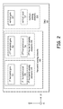
- Figure 2 is a block diagram representative of an inertial measurement unit 110 in accordance with the present invention. As shown in Figures 1 and 2 , the vertical axis in a first orientation is the axis labeled z 1 , a first horizontal axis is the axis labeled y 1 , and a second horizontal axis is the axis labeled x 1 .
- the inertial measurement unit 110 includes a first-horizontal-sensing gyroscope 111, a first-horizontal-sensing accelerometer 115, a second-horizontal-sensing gyroscope 112, a second-horizontal-sensing accelerometer 116, a vertical-sensing gyroscope 113, and a vertical-sensing accelerometer 117.
- the first-horizontal-sensing gyroscope 111 is also referred to herein as a "horizontal-sensing gyroscope 111”
- the first-horizontal-sensing accelerometer 115 is also referred to herein as "horizontal-sensing accelerometer 115.”
- the vertical-sensing gyroscope 113 and the vertical-sensing accelerometer 117 together form the vertical-sensing elements 150.
- the vertical-sensing elements 150 are also referred to herein as "off-horizontal-sensing elements 150." In one implementation of this embodiment, the off-horizontal-sensing elements 150 are not perpendicular to the horizontal-sensing elements 140.
- the first-horizontal-sensing gyroscope 111 and the first-horizontal-sensing accelerometer 115 together form the first-horizontal-sensing elements 139.
- the second-horizontal-sensing gyroscope 112 and the second-horizontal-sensing accelerometer 116 together form the second-horizontal-sensing elements 145.
- the first-horizontal-sensing elements 139 and the second-horizontal-sensing elements 145 together form the horizontal-sensing elements 140.
- the vertical-sensing elements 150 and the horizontal-sensing elements 140 together form the inertial measurement unit 110.
- the second-horizontal-sensing elements 145 are not included in the inertial measurement unit 110.
- a horizontal-sensing gyroscope is sensitive to rotations about a horizontal axis that lies in a horizontal plane and the horizontal-sensing accelerometer is sensitive to accelerations along the horizontal axis.
- a vertical-sensing gyroscope is sensitive to rotations about a vertical axis that is perpendicular to the horizontal plane and the vertical-sensing accelerometer is sensitive to accelerations along the vertical axis.
- Figure 3 shows a rotational device 200 on which the inertial measurement unit 110 is shown positioned in a first orientation 170 and a second orientation 175 in accordance with the present invention.
- the inertial measurement unit 110 and the axes (x 2 , y 2 , z 2 ) in the second orientation 175 are shown in dashed lines to emphasize that the inertial measurement unit 110 is only oriented in one of the first orientation 170 and the second orientation 175 at any given time.
- the inertial measurement unit 110 is located between the first orientation 170 and the second orientation 175.
- the second horizontal axis x 1 ( Figures 1 and 2 ) is parallel to and offset from a horizontal-rotation axis 191 of the rotational device 200.
- the second horizontal axis x 1 is parallel to and aligned with the horizontal-rotation axis 191 of a rotational device 200.
- the inertial measurement unit 110 is positioned inside the rotational device or the rotational device is a structure attached to the inertial measurement unit in a way that permits the rotation of the inertial measurement unit about the horizontal-rotation axis 191 of a rotational device.
- the first-horizontal-sensing elements 139 are aligned with the first horizontal axis y 1
- the second-horizontal-sensing elements 145 are aligned with the second horizontal axis x 1
- the vertical-sensing elements 150 are aligned with the vertical axis z 1 .
- Figure 4 shows the inertial measurement unit 110 of Figure 3 with respect to earth-referenced axes (x e , y e , z e ).
- the horizontal reference plane spanned by the axes (x 1 , y 1 ) ( Figure 3 ) is parallel to the plane spanned by earth-referenced axes (x e , y e ).
- the line 51 extending through the center "c" of the earth 50 to the inertial measurement unit 110 intersects the surface of the earth 50 at the point 52.
- the plane spanned by earth-referenced axes (x e , y e ) is tangential to the earth at point 52 and is perpendicular to the line 51.
- Line 51 is parallel to and aligned with the axis z e .
- the axis x 1 ( Figure 3 ) is parallel to the earth-referenced axis x e
- the axis y 1 ( Figure 3 ) is parallel to the earth-referenced axis y e
- the inertial measurement unit 110 in a vehicle flying above the earth 50 is intersected by the earth-referenced axis z e .
- the vehicle generally travels within the plane spanned by axes (x 1 , y 1 ) that is parallel to the plane spanned by the axes (x e , y e ), without significant movement along the z 1 (or z e ) axis.
- the rotational device 200 is oriented to position the inertial measurement unit 110 in the first orientation 170 and then undergoes a rotation of a selected-rotation angle ⁇ r in the direction of a forward rotation 195, the rotational device 200 is then oriented in the second orientation 175.
- the first-horizontal-sensing elements 139 are aligned with the second horizontal axis y 2
- the second-horizontal-sensing elements 145 are aligned with the second horizontal axis x 2
- the vertical-sensing elements 150 are aligned with the axis z 2 .
- the axis x 1 is parallel to and offset from axis x 2
- the axis y 1 is parallel to and offset from axis z 2
- axis z 1 is anti-parallel to and offset from axis y 2 .
- the axis y 2 is parallel to and in the opposite direction of axis z e and the axis z 2 is parallel to and in the same direction as axis y e .
- the rotational device 200 then undergoes a rotation of a selected-rotation angle ⁇ r in the direction of a back rotation 196, and the rotational device 200 is then re-oriented in the first orientation 170.
- the rotational device 200 periodically rotates between the first orientation 170 and the second orientation 175.
- the inertial navigation system 100 uses the horizontal aiding measurements to calibrate the first-horizontal-sensing elements 139 and the second-horizontal-sensing elements 145 while the inertial measurement unit 110 is in the first orientation 170 and uses the horizontal aiding measurements to calibrate the vertical-sensing elements 150 and second-horizontal-sensing elements 145 while the inertial measurement unit 110 is in the second orientation 175.
- the horizontal velocity reference and/or horizontal position reference are used to calibrate all the sensing elements in the inertial measurement unit 110 along three axes.
- the three axes are orthogonal to each other.
- the selected-rotation angle ⁇ r is a 90° rotation so the rotational device 200 is rotated in the forward direction 195 by the selected-rotation angle of 90° and is then back-rotated in the back-direction 196 by a selected-rotation angle of 90°.
- the rotational device 200 is rotated in the forward direction 195 by a first selected-rotation angle of 90° and is then further rotated in the forward direction 195 by a second selected-rotation angle of 270 °.
- Figure 5 shows one embodiment of an inertial measurement unit 110 on a rotational device 200 in accordance with the present invention.
- the rotational device 200 is mechanically coupled to a servomotor 260 by a precision gear head 265.
- the servomotor 260 is an automatic device which provides rotary (angular) control with an error-sensing feedback to correct the performance of the rotational device.
- the precision gear head 265 is aligned to the horizontal-rotation axis 191 of the rotational device 200.
- a solenoid 270 is communicatively coupled to the rotational device 200 to control the rotation.
- indexing pins are placed in holes 271 in the rotational device 200 to form a pair of stops to mechanically limit the angular rotation of the precision gear head 256 to a selected-rotation angle ⁇ r .
- the inertial measurement unit 110 on an outer surface of the rotational device 200 is rotated between the first orientation and the second orientation responsive to receiving control signals from the software control component in a motor controller 275.
- the selected-rotation angle Or is a ninety degree rotation.
- Figure 6 is a flow diagram of one embodiment of a method 600 to stabilize heading in an inertial navigation system in accordance with the present invention.
- the embodiment of method 600 is described as being implemented using the inertial navigation system 100 of Figure 1 .
- at least a portion of the processing of method 600 is performed by software module 300 executed by the navigation processor 250 to perform the processing described here as being carried out by the software module 300.
- the software module 300 includes program instructions that are stored on, or otherwise embodied on or in, one or more items of storage media 215 (only one of which is shown in Figure 1 ). It is to be understood that method 600 can be implemented using other embodiments of the inertial navigation system 100.
- an inertial measurement unit 110 comprising horizontal-sensing elements 140 and off-horizontal-sensing elements 150 is operated while the inertial measurement unit 110 is in a first orientation 170.
- the horizontal-sensing elements 140 are oriented in a horizontal reference plane, such as (x 1 , y 1 ).
- the first orientation 170 is also referred to herein as the un-rotated position 170.
- the method of operating the inertial measurement unit 110 in a first orientation 170 includes the process of sensing by the horizontal-sensing elements 140 and the off-horizontal-sensing elements 150 ( Figure 2 ) in the inertial measurement unit 110.
- the horizontal-sensing gyroscope 111 oriented to be sensitive to a first-horizontal axis y 1 ( Figure 3 ) generates information indicative of a horizontal axis tilt error.
- the first-horizontal axis y 1 is orthogonal to the horizontal-rotation axis 191.
- the horizontal-sensing accelerometer 115 oriented to be sensitive to the first-horizontal axis y 1 generates information indicative of a horizontal velocity.
- the vertical-sensing gyroscope 113 oriented to be sensitive to a vertical axis z 1 generates information indicative of a vertical axis heading.
- the vertical axis z 1 is orthogonal to the horizontal-rotation axis 191 and the first-horizontal axis y 1 .
- the vertical-sensing accelerometer 117 oriented to be sensitive to the vertical axis z 1 generates information indicative of a vertical velocity.
- the horizontal-sensing elements 140 of the inertial measurement unit 110 are calibrated based on horizontal aiding measurements.
- the first-horizontal-sensing gyroscope 111 and the first-horizontal-sensing accelerometer 115 are calibrated based on horizontal aiding measurements received at the Kalman filter 320 while the inertial measurement unit 110 is operated in the un-rotated orientation 170.
- the second-horizontal-sensing gyroscope 112 and the second-horizontal-sensing accelerometer 116 are calibrated based on horizontal aiding measurements received while operating the inertial measurement unit 110 in the un-rotated orientation 170.
- the Kalman filter 320 corrects the navigation solution 280 for the inertial navigation system 100 based on the calibrating of the horizontal-sensing elements 140.
- FIG 7 is a block diagram of the operation of the inertial navigation system 100 during the calibration process.
- the horizontal aiding measurements which include the horizontal velocity reference 146 and/or the horizontal position reference 141, are received at the Kalman filter 320 from the horizontal position sensor 142 and the horizontal velocity sensor 148 ( Figure 1 ).
- the Kalman filter 320 receives information indicative of the horizontal axis tilt error from the horizontal-sensing elements 140.
- the Kalman filter 320 receives information indicative of the horizontal axis tilt error from the first-horizontal-sensing gyroscope 111 and the second-horizontal-sensing gyroscope 112.
- the Kalman filter 320 receives information indicative of the horizontal axis tilt error from the first and second horizontal accelerometers 115 and 116, respectively.
- the Kalman filter 320 receives information indicative of the vertical axis heading error from the vertical gyroscope 113.
- the Kalman filter 320 receives information indicative of the vertical velocity from the vertical-sensing accelerometer 117.
- the inertial measurement unit 110 sends the information indicative of horizontal axis tilt error, vertical axis heading error, horizontal velocity, and vertical velocity to the sensor compensator 305, which is communicatively coupled to the navigation module that is shown as a strapdown navigator 311 in Figure 7 .
- the strapdown navigator 311 sends the information to the Kalman filter 320.
- the Kalman filter 320 estimates a un-rotated-horizontal-axis-position error based on the information received from the inertial measurement unit 110 in the un-rotated orientation 170.
- the Kalman filter 320 corrects the navigation solution 280 and updates the gyroscope bias estimate at the sensor compensator 305.
- the sensor compensator 305 updates the data input from the inertial measurement unit 110 and then outputs the updated inertial measurement unit data to the strapdown navigator 311.
- the strapdown navigator outputs the corrected navigation solution 280 to the Kalman filter and an external system 30 for use by the external system 30.
- the inertial measurement unit 110 is forward-rotated by a selected-rotation angle ⁇ r about a horizontal-rotation axis 191.
- the horizontal-rotation axis 191 is orthogonal to the direction sensed by the horizontal-sensing elements 139 that include the horizontal-sensing gyroscope 111.
- the inertial measurement unit 110 is oriented in the second or rotated orientation 175 ( Figure 1 and 3 ).
- the vertical-sensing elements 150 Figure 3
- the vertical-sensing elements 150 are oriented in the horizontal reference plane spanned by the axes (x 1 , y 1 ).
- the software control component 330 ( Figure 1 ) sends a forward-rotation control signal to the rotational device 200 to initiate the forward-rotation of the rotational device 200 on which the inertial measurement unit 110 is positioned.
- the forward-rotation is a plus-ninety degree rotation of a selected axis, such as axis z 1 , so that the selected axis (axis z 1 ) is rotated ninety degrees in the direction of forward rotation 195 ( Figure 3 ).
- the forward-rotated inertial measurement unit 110 is operated while the inertial measurement unit 110 is in the second or rotated orientation 175.
- the method of operating the inertial measurement unit 110 in the second orientation 175 includes the process of sensing by the horizontal-sensing elements 140 and the off-horizontal-sensing elements 150 ( Figure 2 ) in the inertial measurement unit 110.
- the first-horizontal axis y 1 is parallel to and offset from the axis z 2 at the second orientation 175.
- the vertical axis z 1 is anti-parallel to and offset from the axis y 2 at the second orientation 175.
- the first- horizontal-sensing elements 139 (including the horizontal-sensing gyroscope 111) are now oriented to be sensitive to a vertical axis y 2 ( Figure 3 ) and to generate information indicative of a vertical axis heading error.
- the vertical-sensing elements 150 (including the vertical-sensing gyroscope 113) are now oriented to be sensitive to axis z 2 , which lies in the plane (x 2 , z 2 ) that is parallel to the horizontal reference plane spanned by the axes (x 1 , y 1 ).
- the vertical-sensing gyroscope 113 oriented to be sensitive to the first-horizontal axis y 1 , which is parallel to and offset from the axis z 2 , generates information indicative of the horizontal axis tilt error.
- the vertical-sensing accelerometer 117 oriented to be sensitive to the first-horizontal axis y 1 generates information indicative of the horizontal velocity.
- the horizontal-sensing gyroscope 111 oriented to be sensitive to the vertical axis z 1 , which is parallel to and offset from the axis y 2 , generates information indicative of the vertical axis heading error.
- the horizontal-sensing accelerometer 115 oriented to be sensitive to the vertical axis z 1 generates information indicative of the vertical velocity.
- the rotated off-horizontal-sensing elements 150 are calibrated based on horizontal aiding measurements while the inertial measurement unit 110 is in the second orientation 175.
- the vertical-sensing gyroscope 113 and the vertical-sensing accelerometer 117 are calibrated based on horizontal aiding measurements received while operating the inertial measurement unit 110 in the rotated orientation 175.
- the second-horizontal-sensing gyroscope 112 and the second-horizontal-sensing accelerometer 116 are calibrated based on horizontal aiding measurements received while operating the inertial measurement unit 110 in the rotated orientation 175.
- the calibration of the rotated off-horizontal-sensing elements 150 is described with reference to Figure 7 .
- the horizontal aiding measurements are received at the Kalman filter 320 from the horizontal position sensor 142 and the horizontal velocity sensor 148 in the sensors 130 ( Figure 1 ).
- the Kalman filter 320 receives information indicative of the horizontal axis tilt error from the vertical-sensing gyroscope 113.
- the Kalman filter 320 receives information indicative of the horizontal velocity from vertical-sensing accelerometer 117.
- the Kalman filter 320 receives information indicative of the vertical axis heading error and information indicative of the vertical velocity from the first-horizontal-sensing elements 139 in the inertial measurement unit 110 in the rotated orientation.
- the Kalman filter 320 estimates a rotated-horizontal-axis-position error based on the information received from the inertial measurement unit 110 in the rotated orientation 175.
- the Kalman filter 320 estimates a rotated-horizontal-axis-velocity error based on the information received from the inertial measurement unit 110 in the rotated orientation 175.
- the Kalman filter 320 corrects the navigation solution 280 for the inertial navigation system 100 based on the calibrating of the off-horizontal-sensing elements 150 in the inertial measurement unit.
- the Kalman filter 320 corrects the navigation solution 280 and updates the gyroscope bias estimate at the sensor compensator 305.
- the sensor compensator 305 updates the data input from the inertial measurement unit 110 and then outputs the updated inertial measurement unit data to the strapdown navigator 311.
- the strapdown navigator outputs the corrected navigation solution 280 to the Kalman filter 320 and an external system 30 for use by the external system 30.
- the vertical-sensing elements 150 and horizontal-sensing elements 140 are all calibrated at blocks 612 and 604, respectively, and the navigation solution 280 is corrected after each calibration at blocks 614 and 606, respectively.
- the inertial measurement unit 110 is back-rotated about the horizontal-rotation axis 191 by the selected-rotation angle ⁇ r .
- the inertial measurement unit 110 is oriented in the first orientation 170 after the inertial measurement unit 110 is back-rotated about the horizontal-rotation axis 191 by the selected-rotation angle ⁇ r .
- the software control component 330 ( Figure 1 ) sends a back-rotation control signal to the rotational device 200 to initiate the back-rotation of the rotational device 200 on which the inertial measurement unit 110 is positioned.
- the back-rotation is a minus-ninety degree rotation of a selected axis, such as axis z 1 , so that the selected axis (axis z 1 ) is rotated ninety degrees in the direction of back rotation 196 ( Figure 3 ).
- the inertial measurement unit 110 is further-forward-rotated about the horizontal-rotation axis 191 by a second selected-rotation angle (360°- ⁇ r ), wherein the inertial measurement unit 110 is oriented in the first orientation 170 after the inertial measurement unit 110 is further-forward-rotated about the horizontal-rotation axis 191 by the second selected-rotation angle (360°- ⁇ r ).
- the selected-rotation angle is 90° and the second selected-rotation angle is 270°.
- the software control component 330 ( Figure 1 ) sends a further-forward-rotation control signal to the rotational device 200 to initiate the further-forward-rotation of the rotational device 200 on which the inertial measurement unit 110 is positioned.
- the flow of method 600 proceeds back to block 602 and the inertial measurement unit 110 is operated while the inertial measurement unit 110 is in the first orientation 170.
- the horizontal-sensing elements 140 of the inertial measurement unit 110 are re-calibrated based on horizontal aiding measurements while the inertial measurement unit 110 is in the first orientation 170.
- the Kalman filter is able to estimate heading drift, attribute the drift to a specific gyro, calibrate all gyros and correct for position and velocity errors due to vertical angular drift.
- the Kalman filter 320 generates an error estimate for the navigation solution 280 based at least in part on the input data from the inertial measurement unit 110 and the sensors 130.
- the forward-rotation and back-rotation occur periodically.
- the inertial measurement unit 110 is periodically forward-rotated through a plus-ninety degree rotation and back-rotated through a minus-ninety degree rotation responsive to each forward rotation.
- the period of the rotation is based on the length of time that the gyroscopes and accelerometers hold the calibrations.
- the calibration of the gyroscopes and accelerometers holds for ten minutes and the rotational device 200 rotates the inertial measurement unit 110 every ten minutes.
- the calibration of the gyroscopes and accelerometers holds for thirty seconds and the rotational device 200 rotates the inertial measurement unit 110 every thirty seconds.
- the time taken to rotate the inertial measurement unit about the horizontal rotation axis 191 from the un-rotated orientation 170 to the rotated orientation 175 is much less than the period of time between the forward-rotation and the back-rotation. In one implementation of this embodiment, the time taken to rotate the inertial measurement unit about the horizontal rotation axis 191 from the un-rotated orientation 170 to the rotated orientation 175 is about one second.
- the method of stabilizing heading in an inertial navigation system is applied to a vehicle that is generally moving in a vertical direction of a vertical plane (e.g., the plane spanned by (x 1 , z 1 ) or the plane spanned by (y 1 , z 1 )), rather than in a horizontal direction of a horizontal plane, and the vehicle is receiving information indicative of vertical velocity reference and/or vertical position reference.
- a vehicle that would be making such a motion is an underwater vehicle that is moving between the ocean floor and the surface of the ocean.
- the rotation axis would be about a vertical axis (e.g., z 1 ) rather than the horizontal-rotation axis 191 and the Kalman filter 320 compares the data received from the first-horizontal-sensing elements 139 and the second-horizontal-sensing elements 145 as is understandable by one skilled in the art upon reading this document.
Landscapes
- Engineering & Computer Science (AREA)
- Radar, Positioning & Navigation (AREA)
- Remote Sensing (AREA)
- Physics & Mathematics (AREA)
- General Physics & Mathematics (AREA)
- Automation & Control Theory (AREA)
- Manufacturing & Machinery (AREA)
- Navigation (AREA)
Applications Claiming Priority (2)
| Application Number | Priority Date | Filing Date | Title |
|---|---|---|---|
| US91202607P | 2007-04-16 | 2007-04-16 | |
| US12/059,837 US8019542B2 (en) | 2007-04-16 | 2008-03-31 | Heading stabilization for aided inertial navigation systems |
Publications (3)
| Publication Number | Publication Date |
|---|---|
| EP1983304A2 true EP1983304A2 (de) | 2008-10-22 |
| EP1983304A3 EP1983304A3 (de) | 2014-08-27 |
| EP1983304B1 EP1983304B1 (de) | 2020-07-22 |
Family
ID=39712603
Family Applications (1)
| Application Number | Title | Priority Date | Filing Date |
|---|---|---|---|
| EP08103532.1A Active EP1983304B1 (de) | 2007-04-16 | 2008-04-14 | Kursstabilisierung für unterstützte Trägheitsnavigationssysteme |
Country Status (3)
| Country | Link |
|---|---|
| US (1) | US8019542B2 (de) |
| EP (1) | EP1983304B1 (de) |
| AU (1) | AU2008201684A1 (de) |
Cited By (4)
| Publication number | Priority date | Publication date | Assignee | Title |
|---|---|---|---|---|
| DE102008058866A1 (de) | 2008-11-26 | 2010-06-17 | Lfk-Lenkflugkörpersysteme Gmbh | Vorrichtung und Verfahren zur Lagebestimmung eines Objekts |
| WO2011063280A3 (en) * | 2009-11-20 | 2011-09-29 | Qualcomm Incorporated | Spatial alignment determination for an inertial measurement unit (imu) |
| RU2447404C2 (ru) * | 2010-06-16 | 2012-04-10 | Открытое акционерное общество "Конструкторское Бюро Промышленной Автоматики" | Способ калибровки датчиков угловой скорости бесплатформенного инерциального измерительного модуля |
| CN103917343A (zh) * | 2011-08-03 | 2014-07-09 | 多样桶解决方案有限公司 | 包含具有可移动激光组件的机械臂的用于修复桶的系统和方法 |
Families Citing this family (10)
| Publication number | Priority date | Publication date | Assignee | Title |
|---|---|---|---|---|
| JP5270184B2 (ja) * | 2008-02-13 | 2013-08-21 | 古野電気株式会社 | 衛星航法/推測航法統合測位装置 |
| US8660717B2 (en) * | 2009-03-10 | 2014-02-25 | Atair Aerospace | Method of correcting guidance commands for fluid medium |
| US9599474B2 (en) * | 2009-04-06 | 2017-03-21 | Honeywell International Inc. | Technique to improve navigation performance through carouselling |
| US8589015B2 (en) * | 2010-02-12 | 2013-11-19 | Webtech Wireless Inc. | Vehicle sensor calibration for determining vehicle dynamics |
| CN102865881B (zh) * | 2012-03-06 | 2014-12-31 | 武汉大学 | 一种惯性测量单元的快速标定方法 |
| US10132647B2 (en) * | 2013-10-24 | 2018-11-20 | Mtd Products Inc | Methods and apparatus for increasing accuracy and reliability of gyrosopic sensors |
| US20150358522A1 (en) * | 2014-03-31 | 2015-12-10 | Goodrich Corporation | Stabilization Of Gyro Drift Compensation For Image Capture Device |
| DE102015113486A1 (de) * | 2015-08-14 | 2017-02-16 | Northrop Grumman Litef Gmbh | Navigationsvorrichtung mit Drehtisch für eine Umschlagsmessung und Verfahren zum Betreiben der Navigationsvorrichtung |
| US10180686B2 (en) * | 2016-03-17 | 2019-01-15 | Mitsubishi Electric Research Laboratories, Inc. | Concurrent station keeping, attitude control, and momentum management of spacecraft |
| US10533856B2 (en) | 2017-04-05 | 2020-01-14 | Novatel Inc. | Navigation system utilizing yaw rate constraint during inertial dead reckoning |
Family Cites Families (18)
| Publication number | Priority date | Publication date | Assignee | Title |
|---|---|---|---|---|
| US3509765A (en) * | 1965-12-17 | 1970-05-05 | Gen Motors Corp | Inertial navigation system |
| US4212443A (en) | 1978-05-18 | 1980-07-15 | Sperry Corporation | Strapped down attitude and heading reference system for aircraft employing skewed axis two-degree-of-freedom rate gyros |
| US4800501A (en) | 1986-11-24 | 1989-01-24 | Ivan Kinsky | Vehicle land navigating device |
| US5060392A (en) * | 1990-07-09 | 1991-10-29 | Allied-Signal Inc. | North finding system |
| US5421187A (en) | 1993-12-28 | 1995-06-06 | Honeywell Inc. | Calibration of an internal sensor system |
| DE19721217C1 (de) | 1997-05-21 | 1998-08-27 | Daimler Benz Aerospace Ag | Vorrichtung zur Kalibrierung mehrerer Kreiselsysteme |
| US6421622B1 (en) * | 1998-06-05 | 2002-07-16 | Crossbow Technology, Inc. | Dynamic attitude measurement sensor and method |
| US6152403A (en) | 1998-11-11 | 2000-11-28 | Hughes Electronics Corporation | Gyroscopic calibration methods for spacecraft |
| US6427122B1 (en) * | 2000-12-23 | 2002-07-30 | American Gnc Corporation | Positioning and data integrating method and system thereof |
| US6778924B2 (en) | 2001-11-06 | 2004-08-17 | Honeywell International Inc. | Self-calibrating inertial measurement system method and apparatus |
| DE60139881D1 (de) | 2001-11-13 | 2009-10-22 | Nokia Corp | Verfahren, Vorrichtung und System zur Kalibrierung von Winkelratenmesssensoren |
| US6778908B2 (en) * | 2002-06-25 | 2004-08-17 | The Charles Stark Draper Laboratory, Inc. | Environmentally mitigated navigation system |
| WO2004013573A2 (en) * | 2002-08-01 | 2004-02-12 | The Charles Stark Draper Laboratory, Inc. | Borehole navigation system |
| US7066004B1 (en) * | 2004-09-02 | 2006-06-27 | Sandia Corporation | Inertial measurement unit using rotatable MEMS sensors |
| US7275008B2 (en) | 2005-09-02 | 2007-09-25 | Nokia Corporation | Calibration of 3D field sensors |
| CN100516775C (zh) * | 2006-08-23 | 2009-07-22 | 北京航空航天大学 | 一种捷联惯性导航系统初始姿态确定方法 |
| US9858712B2 (en) * | 2007-04-09 | 2018-01-02 | Sam Stathis | System and method capable of navigating and/or mapping any multi-dimensional space |
| US9599474B2 (en) * | 2009-04-06 | 2017-03-21 | Honeywell International Inc. | Technique to improve navigation performance through carouselling |
-
2008
- 2008-03-31 US US12/059,837 patent/US8019542B2/en active Active
- 2008-04-14 EP EP08103532.1A patent/EP1983304B1/de active Active
- 2008-04-16 AU AU2008201684A patent/AU2008201684A1/en not_active Abandoned
Cited By (10)
| Publication number | Priority date | Publication date | Assignee | Title |
|---|---|---|---|---|
| DE102008058866A1 (de) | 2008-11-26 | 2010-06-17 | Lfk-Lenkflugkörpersysteme Gmbh | Vorrichtung und Verfahren zur Lagebestimmung eines Objekts |
| DE102008058866B4 (de) | 2008-11-26 | 2018-09-13 | Mbda Deutschland Gmbh | Vorrichtung und Verfahren zur Lagebestimmung eines Objekts |
| WO2011063280A3 (en) * | 2009-11-20 | 2011-09-29 | Qualcomm Incorporated | Spatial alignment determination for an inertial measurement unit (imu) |
| CN102648394A (zh) * | 2009-11-20 | 2012-08-22 | 高通股份有限公司 | 惯性测量单元(imu)的空间对准确定 |
| US8781737B2 (en) | 2009-11-20 | 2014-07-15 | Qualcomm Incorporated | Spatial alignment determination for an inertial measurement unit (IMU) |
| KR101422374B1 (ko) * | 2009-11-20 | 2014-07-22 | 퀄컴 인코포레이티드 | 관성 측정 유닛(imu)에 대한 공간 정렬 결정 |
| TWI457538B (zh) * | 2009-11-20 | 2014-10-21 | Qualcomm Inc | 用於慣性量測單元(imu)的空間校準決定的方法、儲存媒體及設備 |
| CN102648394B (zh) * | 2009-11-20 | 2015-12-09 | 高通股份有限公司 | 惯性测量单元(imu)的空间对准确定 |
| RU2447404C2 (ru) * | 2010-06-16 | 2012-04-10 | Открытое акционерное общество "Конструкторское Бюро Промышленной Автоматики" | Способ калибровки датчиков угловой скорости бесплатформенного инерциального измерительного модуля |
| CN103917343A (zh) * | 2011-08-03 | 2014-07-09 | 多样桶解决方案有限公司 | 包含具有可移动激光组件的机械臂的用于修复桶的系统和方法 |
Also Published As
| Publication number | Publication date |
|---|---|
| US20080319667A1 (en) | 2008-12-25 |
| EP1983304B1 (de) | 2020-07-22 |
| US8019542B2 (en) | 2011-09-13 |
| EP1983304A3 (de) | 2014-08-27 |
| AU2008201684A1 (en) | 2008-10-30 |
Similar Documents
| Publication | Publication Date | Title |
|---|---|---|
| US8019542B2 (en) | Heading stabilization for aided inertial navigation systems | |
| ES2360137T3 (es) | Procedimiento de verificación de una unidad de medida inercial de vehículos, especialmente de vehículos aéreos, en estado estacionario. | |
| CN102192741B (zh) | 飞行器姿态角的旋转稳定估计 | |
| US8185309B2 (en) | Enhanced inertial system performance | |
| US7979231B2 (en) | Method and system for estimation of inertial sensor errors in remote inertial measurement unit | |
| EP2259023B1 (de) | Fehlerkorrektur für ein Inertialnavigationssystem | |
| US7587277B1 (en) | Inertial/magnetic measurement device | |
| EP1941236B1 (de) | Systeme und verfahren zur verringerung vibrationsbedingter fehler in trägheitssensoren | |
| EP2472225B1 (de) | Verfahren und System zur anfänglichen Quaternion- und Lageschätzung | |
| CN112595350A (zh) | 一种惯导系统自动标定方法及终端 | |
| CN104181574A (zh) | 一种捷联惯导系统/全球导航卫星系统组合导航滤波系统及方法 | |
| KR102360465B1 (ko) | 항법용 관성센서 캘리브레이션 방법 | |
| EP3848672B1 (de) | Integriertes trägheitsgravitationsanomalienavigationssystem | |
| CN105352527B (zh) | 一种基于双轴转位机构光纤陀螺标定方法 | |
| EP2587219A1 (de) | Verfahren zum Verbessern der Nivellierungsleistung von Navigationssystemen | |
| KR101564020B1 (ko) | 이동체의 전자세 예측 방법 및 이를 이용한 전자세 예측 장치 | |
| CN110514201B (zh) | 一种惯性导航系统及适用于高转速旋转体的导航方法 | |
| US8725415B2 (en) | Method and device for long-duration navigation | |
| CA2722057A1 (en) | Rate of turn signal generator with drift compensation | |
| CN108931247B (zh) | 一种导航方法和装置 | |
| RU2539131C1 (ru) | Бесплатформенная интегрированная навигационная система средней точности для мобильного наземного объекта | |
| Rios et al. | Low cost solid state GPS/INS package | |
| CN113758502B (zh) | 组合导航处理方法及装置 | |
| JP2016031283A (ja) | 角速度センサ装置および角速度センサ補正方法 | |
| CN112710315A (zh) | 一种基于智能车辆的车辆定位方法及装置 |
Legal Events
| Date | Code | Title | Description |
|---|---|---|---|
| PUAI | Public reference made under article 153(3) epc to a published international application that has entered the european phase |
Free format text: ORIGINAL CODE: 0009012 |
|
| 17P | Request for examination filed |
Effective date: 20080414 |
|
| AK | Designated contracting states |
Kind code of ref document: A2 Designated state(s): AT BE BG CH CY CZ DE DK EE ES FI FR GB GR HR HU IE IS IT LI LT LU LV MC MT NL NO PL PT RO SE SI SK TR |
|
| AX | Request for extension of the european patent |
Extension state: AL BA MK RS |
|
| PUAL | Search report despatched |
Free format text: ORIGINAL CODE: 0009013 |
|
| AK | Designated contracting states |
Kind code of ref document: A3 Designated state(s): AT BE BG CH CY CZ DE DK EE ES FI FR GB GR HR HU IE IS IT LI LT LU LV MC MT NL NO PL PT RO SE SI SK TR |
|
| AX | Request for extension of the european patent |
Extension state: AL BA MK RS |
|
| RIC1 | Information provided on ipc code assigned before grant |
Ipc: G01C 25/00 20060101AFI20140723BHEP Ipc: G01C 21/16 20060101ALI20140723BHEP |
|
| 17Q | First examination report despatched |
Effective date: 20140821 |
|
| AKX | Designation fees paid |
Designated state(s): DE GB |
|
| AXX | Extension fees paid |
Extension state: AL Extension state: RS Extension state: MK Extension state: BA |
|
| RAP1 | Party data changed (applicant data changed or rights of an application transferred) |
Owner name: HONEYWELL INTERNATIONAL INC. |
|
| STAA | Information on the status of an ep patent application or granted ep patent |
Free format text: STATUS: EXAMINATION IS IN PROGRESS |
|
| RIN1 | Information on inventor provided before grant (corrected) |
Inventor name: ROLFER, TOM Inventor name: HAWKINSON, WESLEY J. |
|
| GRAP | Despatch of communication of intention to grant a patent |
Free format text: ORIGINAL CODE: EPIDOSNIGR1 |
|
| STAA | Information on the status of an ep patent application or granted ep patent |
Free format text: STATUS: GRANT OF PATENT IS INTENDED |
|
| INTG | Intention to grant announced |
Effective date: 20190124 |
|
| GRAJ | Information related to disapproval of communication of intention to grant by the applicant or resumption of examination proceedings by the epo deleted |
Free format text: ORIGINAL CODE: EPIDOSDIGR1 |
|
| STAA | Information on the status of an ep patent application or granted ep patent |
Free format text: STATUS: EXAMINATION IS IN PROGRESS |
|
| INTC | Intention to grant announced (deleted) | ||
| GRAP | Despatch of communication of intention to grant a patent |
Free format text: ORIGINAL CODE: EPIDOSNIGR1 |
|
| STAA | Information on the status of an ep patent application or granted ep patent |
Free format text: STATUS: GRANT OF PATENT IS INTENDED |
|
| GRAJ | Information related to disapproval of communication of intention to grant by the applicant or resumption of examination proceedings by the epo deleted |
Free format text: ORIGINAL CODE: EPIDOSDIGR1 |
|
| GRAJ | Information related to disapproval of communication of intention to grant by the applicant or resumption of examination proceedings by the epo deleted |
Free format text: ORIGINAL CODE: EPIDOSDIGR1 |
|
| GRAP | Despatch of communication of intention to grant a patent |
Free format text: ORIGINAL CODE: EPIDOSNIGR1 |
|
| STAA | Information on the status of an ep patent application or granted ep patent |
Free format text: STATUS: EXAMINATION IS IN PROGRESS |
|
| GRAP | Despatch of communication of intention to grant a patent |
Free format text: ORIGINAL CODE: EPIDOSNIGR1 |
|
| STAA | Information on the status of an ep patent application or granted ep patent |
Free format text: STATUS: GRANT OF PATENT IS INTENDED |
|
| INTG | Intention to grant announced |
Effective date: 20200219 |
|
| INTG | Intention to grant announced |
Effective date: 20200219 |
|
| INTG | Intention to grant announced |
Effective date: 20200304 |
|
| INTC | Intention to grant announced (deleted) | ||
| INTG | Intention to grant announced |
Effective date: 20200318 |
|
| GRAS | Grant fee paid |
Free format text: ORIGINAL CODE: EPIDOSNIGR3 |
|
| GRAA | (expected) grant |
Free format text: ORIGINAL CODE: 0009210 |
|
| STAA | Information on the status of an ep patent application or granted ep patent |
Free format text: STATUS: THE PATENT HAS BEEN GRANTED |
|
| AK | Designated contracting states |
Kind code of ref document: B1 Designated state(s): DE GB |
|
| REG | Reference to a national code |
Ref country code: GB Ref legal event code: FG4D |
|
| REG | Reference to a national code |
Ref country code: DE Ref legal event code: R096 Ref document number: 602008063022 Country of ref document: DE |
|
| REG | Reference to a national code |
Ref country code: DE Ref legal event code: R097 Ref document number: 602008063022 Country of ref document: DE |
|
| PLBE | No opposition filed within time limit |
Free format text: ORIGINAL CODE: 0009261 |
|
| STAA | Information on the status of an ep patent application or granted ep patent |
Free format text: STATUS: NO OPPOSITION FILED WITHIN TIME LIMIT |
|
| 26N | No opposition filed |
Effective date: 20210423 |
|
| P01 | Opt-out of the competence of the unified patent court (upc) registered |
Effective date: 20230525 |
|
| PGFP | Annual fee paid to national office [announced via postgrant information from national office to epo] |
Ref country code: DE Payment date: 20250428 Year of fee payment: 18 |
|
| PGFP | Annual fee paid to national office [announced via postgrant information from national office to epo] |
Ref country code: GB Payment date: 20260313 Year of fee payment: 19 |