EP1983324B1 - Appareil à deux capteurs de pression - Google Patents
Appareil à deux capteurs de pression Download PDFInfo
- Publication number
- EP1983324B1 EP1983324B1 EP08153904A EP08153904A EP1983324B1 EP 1983324 B1 EP1983324 B1 EP 1983324B1 EP 08153904 A EP08153904 A EP 08153904A EP 08153904 A EP08153904 A EP 08153904A EP 1983324 B1 EP1983324 B1 EP 1983324B1
- Authority
- EP
- European Patent Office
- Prior art keywords
- pressure sensor
- manifold
- pressure
- sensor module
- opening
- Prior art date
- Legal status (The legal status is an assumption and is not a legal conclusion. Google has not performed a legal analysis and makes no representation as to the accuracy of the status listed.)
- Active
Links
Images

Classifications
-
- G—PHYSICS
- G01—MEASURING; TESTING
- G01L—MEASURING FORCE, STRESS, TORQUE, WORK, MECHANICAL POWER, MECHANICAL EFFICIENCY, OR FLUID PRESSURE
- G01L15/00—Devices or apparatus for measuring two or more fluid pressure values simultaneously
-
- G—PHYSICS
- G01—MEASURING; TESTING
- G01L—MEASURING FORCE, STRESS, TORQUE, WORK, MECHANICAL POWER, MECHANICAL EFFICIENCY, OR FLUID PRESSURE
- G01L19/00—Details of, or accessories for, apparatus for measuring steady or quasi-steady pressure of a fluent medium insofar as such details or accessories are not special to particular types of pressure gauges
- G01L19/14—Housings
- G01L19/141—Monolithic housings, e.g. molded or one-piece housings
Definitions
- the present invention relates to sensor arrangements for facilitating the control of an internal combustion engine, and more particularly to a dual pressure sensor apparatus for measuring both manifold absolute pressure and barometric pressure.
- MAP Manifold absolute pressure
- BARO barometric pressure
- MAP Manifold absolute pressure
- BARO barometric pressure
- a separate pressure sensor module is used to measure each pressure, the MAP sensor being mounted on the intake manifold and the BARO sensor being mounted elsewhere in the engine compartment.
- Luettgen discloses single a pressure sensor placed in a chamber of two-chamber housing, and electrically connected to a signal processing device placed in the second chamber.
- Baba et al disclose a pressure sensor set within a packaging comprising a barrier wall preventing wire breaking.
- Nagano et al disclose a pressure sensor where atmospheric pressure and fuel tank pressure are introduced on both side of a diaphragm in order for a semiconductor sensor to detect the difference. While it has long been recognized that it is possible to mount both MAP and BARO sensors in one package for lower overall sensor cost, see, for example, the U.S. Patent No. 4,131,088 to Reddy and US 5544529 , widespread usage of dual pressure sensors has not occurred. Accordingly, what is needed is an improved approach to dual pressure sensing.
- the present invention provides an improved dual pressure sensor apparatus for attachment to a manifold, the sensor apparatus including a molded plastic housing with a body portion featuring an upper cavity, a measurement port, and a lower cavity closed by the manifold.
- First and second pressure sensor modules are mounted in first and second wells formed in the upper cavity, and electrically coupled to a set of leadframe terminals disposed in the upper cavity.
- An opening in the first well couples the first pressure sensor module to the measurement port, and an opening in the second well couples the second pressure sensor module to the lower cavity.
- the measurement port sealingly extends through an opening in the manifold so that the first pressure sensor module measures pressure in the manifold, and the body portion walls bounding the lower cavity are notched so that the second pressure sensor module measures atmospheric or barometric pressure outside the manifold.
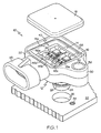
- FIG. 1 is a partially exploded upper isometric view of the dual pressure sensor apparatus of the present invention, including a housing, two pressure sensor modules and a cover.
- FIG. 2 is a lower isometric view of the sensor apparatus of FIG. 1 .
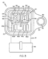
- FIG. 3 is a top view of the sensor apparatus housing of FIG. 1 , without the pressure sensor modules and the cover.
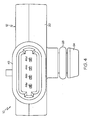
- FIG. 4 is an end view of the sensor apparatus housing of FIG. 1 , without the cover.
- the sensor apparatus of the present invention is disclosed herein in the context of an engine control sensor that measures both MAP and BARO as discussed above.
- the described dual pressure sensor apparatus can be extended to applications in which the manifold-confined pressure is something other the pressure in the intake manifold pressure of an engine.
- the term "manifold” as used herein can be more generally understood to designate the wall of a vessel per se.
- the reference numeral 10 generally designates a preferred embodiment of a dual pressure sensor apparatus that measures both MAP and BARO for the control of an internal combustion engine.
- the sensor apparatus 10 includes a molded plastic housing 12, first and second electronic pressure sensor modules 14 and 16 and a plastic cover 18.
- the pressure sensor modules 14, 16 are identical; each includes a pressure sensor element and signal processing chip(s) mounted on a ceramic substrate 14a, 16a.
- the molded housing 12 includes a generally rectangular body portion 20 that abuts the engine's intake manifold 22 and a MAP measurement port 24 that extends through a smooth opening 26 formed in the manifold 22 so that the outboard end of the measurement port 24 is disposed in the air stream within the manifold 22.
- An O-ring 28 surrounding the measurement port 24 is compressed between the measurement port 24 and the periphery of the manifold opening 26 to prevent leakage into or out of the manifold 22.
- the lug 30 is provided with an opening 32 for receiving a mounting bolt (not shown) that threads into a tapped manifold opening 34 adjacent the opening 26, and a metal bushing 36 insert-molded in the lug opening 32 bears the compressive force of the mounting bolt.
- the body portion 20 of sensor housing 12 additionally includes an upper cavity 40 (that is, a cavity that opens away from the manifold 22), a lower cavity 42 (that is, a cavity that opens toward the manifold 22) closed by the manifold 22, and a connector hood 43.
- the connector hood 43 is designed to mate with a complementary connector (not shown), and a set of four leadframe terminals 44a, 44b, 44c, 44d insert-molded in the sensor housing 12 extend into the connector hood 43 as seen in FIG. 4 . As best seen in FIG.
- the inboard ends of the terminals 44a, 44b, 44c, 44d terminate in a linear array of bond pads 46a, 46b, 46c, 46d on the floor of the upper cavity 40 adjacent the connector hood 43.
- two individual sensor wells 48 and 50 are formed in the floor of upper cavity 40 adjacent the terminal bond pads 46a, 46b, 46c and 46d.
- the pressure sensor module 14 is secured in the sensor well 48 with a peripherally dispensed adhesive
- the pressure sensor module 16 is similarly secured in the sensor well 50.
- the sensor wells 48, 50 each include a central opening 52, 54 and a set of peripheral standoff bumps 56, 58 that support the respective pressure sensor module substrate 14a, 16a.
- the standoff bumps 56, 58 help ensure that the peripheral adhesive between the substrates 14a, 16a and the floor of the respective sensor well 48, 50 will have a uniform thickness for optimal adhesion and sealing.
- the central opening 54 formed in the floor of sensor well 50 opens into a central bore 60 in the measurement port 24 so that the pressure sensor element of sensor module 16 is responsive to the pressure within the manifold 22 (i.e., MAP).
- the central opening 52 formed in the floor of sensor well 48 opens into the lower cavity 42 of body portion 12, as seen in FIG. 2 , so that the pressure sensor element of sensor module 14 is responsive to the pressure within the lower cavity 42.
- the lower cavity 42 is laterally bounded by the sidewalls 20a and 20b of the housing body portion 20, and a pair of peripheral notches 64, 66 in the sidewalls 20a, 20b open the lower cavity 42 to atmospheric air (i.e., barometric pressure) when the sensor apparatus 10 is secured to manifold 22 as described above in respect to FIG. 1 .
- the sensor modules 14 and 16 are electrically coupled to the terminal bond pads 46a-46d by wirebonding.
- the sensor module 14 is wire-bonded to the terminal bond pads 46a, 46d and 46b; and the sensor module 16 is wire-bonded to the terminal bond pads 46b, 46c and 46d.
- the common bond pad 46b supplies operating voltage (power) to sensor modules 14 and 16, and the common bond pad 46d supplies a common ground reference to sensor modules 14 and 16.
- the common bond pad 46b is disposed between the sensor modules 14, 16, and the common bond pad 46d is provided with a lateral trace 46d' to minimize the length of the wirebond between it and the sensor module 14.
- the bond pad 46a and corresponding terminal 44a convey the pressure measurement of sensor module 14 to an engine control module (not shown), and the bond pad 46d and corresponding terminal 44d similarly convey the pressure measurement of sensor module 16.
- a sealant or passivating compound such as silicone is dispensed into the upper cavity 40, and the cover 18 is pressed or glued into a channel 68 surrounding the upper cavity 40.
- the present invention achieves an easily implemented and very cost effective approach to dual pressure sensing. While the present invention has been described with respect to the illustrated embodiment, it is recognized that numerous modifications and variations in addition to those mentioned herein will occur to those skilled in the art. Accordingly, it is intended that the invention not be limited to the disclosed embodiment, but that it have the full scope permitted by the language of the following claims.
Landscapes
- Physics & Mathematics (AREA)
- General Physics & Mathematics (AREA)
- Measuring Fluid Pressure (AREA)
Claims (3)
- Appareil à double capteur de pression, comprenant :un boîtier en matière plastique moulée (12) avec une portion de corps (20) présentant une cavité supérieure (40), un orifice de mesure (24) qui s'étend de manière étanche à travers une ouverture (26) dans un collecteur (22) auquel le boîtier (12) est attaché, et une cavité inférieure (42) partiellement fermée par le collecteur (22), dans lequel une paroi (20a, 20b) de la portion de corps (20) qui borde la cavité inférieure (42) est encochée (64, 66) pour mettre la cavité inférieure (42) à la pression barométrique à l'extérieur du collecteur (22) ;un premier et un second module capteur de pression (16, 14) montés dans un premier et dans un second puits (50, 48) formés dans la cavité supérieure (40) ;une première ouverture (54) dans le premier puits (50) pour coupler le premier module capteur de pression (16) à l'orifice de mesure (24) de sorte que le premier module capteur de pression (16) mesure la pression dans le collecteur (22) ; etune seconde ouverture (52) dans le second puits (48) pour coupler le second module capteur de pression (14) à la cavité inférieure (42) de sorte que le second module capteur de pression (14) mesure la pression barométrique à l'extérieur du collecteur (22).
- Appareil à double capteur de pression selon la revendication 1, comprenant en outre :un groupe de bornes de conducteurs-poutre (40a, 40b, 40d, 40d) moulées sur insert dans le boîtier (12), incluant un réseau de patins de jonction de bornes (46a, 46b, 46c, 46b) sur un plancher de la cavité supérieure (40) ; etun groupe de jonctions à fil qui couplent le premier et le second module capteur de pression (16, 14) aux patins de jonction de bornes (46a, 46b, 46c, 46d).
- Appareil à double capteur de pression selon la revendication 1, comprenant en outre un couvercle (18) fermant ladite cavité supérieure (40).
Applications Claiming Priority (1)
| Application Number | Priority Date | Filing Date | Title |
|---|---|---|---|
| US11/788,470 US7497124B2 (en) | 2007-04-20 | 2007-04-20 | Dual pressure sensor apparatus |
Publications (3)
| Publication Number | Publication Date |
|---|---|
| EP1983324A2 EP1983324A2 (fr) | 2008-10-22 |
| EP1983324A3 EP1983324A3 (fr) | 2010-07-21 |
| EP1983324B1 true EP1983324B1 (fr) | 2011-10-19 |
Family
ID=39637497
Family Applications (1)
| Application Number | Title | Priority Date | Filing Date |
|---|---|---|---|
| EP08153904A Active EP1983324B1 (fr) | 2007-04-20 | 2008-04-01 | Appareil à deux capteurs de pression |
Country Status (3)
| Country | Link |
|---|---|
| US (1) | US7497124B2 (fr) |
| EP (1) | EP1983324B1 (fr) |
| AT (1) | ATE529728T1 (fr) |
Families Citing this family (12)
| Publication number | Priority date | Publication date | Assignee | Title |
|---|---|---|---|---|
| JP4933972B2 (ja) * | 2007-07-24 | 2012-05-16 | 株式会社山武 | デュアル圧力センサ |
| US7765872B2 (en) * | 2008-11-19 | 2010-08-03 | Honeywell International Inc. | Flow sensor apparatus and method with media isolated electrical connections |
| US20120162634A1 (en) * | 2009-07-22 | 2012-06-28 | Continental Teves Ag & Co. Ohg | Speed sensor |
| US9021689B2 (en) | 2011-06-02 | 2015-05-05 | Freescale Semiconductor, Inc. | Method of making a dual port pressure sensor |
| US8307714B1 (en) | 2011-06-02 | 2012-11-13 | Freescale Semiconductor, Inc. | Dual port pressure sensor |
| US8770034B2 (en) * | 2011-09-06 | 2014-07-08 | Honeywell International Inc. | Packaged sensor with multiple sensors elements |
| US9617928B2 (en) * | 2013-04-24 | 2017-04-11 | Ford Global Technologies, Llc | Automotive combination sensor |
| JP6283307B2 (ja) * | 2014-12-24 | 2018-02-21 | 長野計器株式会社 | 物理量測定装置 |
| US20160348618A1 (en) * | 2015-05-26 | 2016-12-01 | Amphenol Thermometrics, Inc. | Intake Air Sensor and Sensing Method for Determining Air Filter Performance, Barometric Pressure, and Manifold Pressure of a Combustion Engine |
| JP6892207B2 (ja) * | 2018-04-10 | 2021-06-23 | 日立Astemo株式会社 | センサユニット |
| DE102019124083B3 (de) * | 2019-09-09 | 2020-10-22 | Ifm Electronic Gmbh | Absolutdruckmessgerät mit einer relativ messenden Druckmesszelle |
| US11767837B2 (en) * | 2019-11-14 | 2023-09-26 | Vanair Manufacturing, Inc. | Compressor control systems and air compressor systems and vehicles equipped therewith |
Family Cites Families (14)
| Publication number | Priority date | Publication date | Assignee | Title |
|---|---|---|---|---|
| US4160600A (en) * | 1976-09-23 | 1979-07-10 | Smiths Industries Limited | Pressure-responsive apparatus |
| US4131088A (en) | 1976-11-08 | 1978-12-26 | The Bendix Corporation | Multiple function pressure sensor |
| JPS5937716Y2 (ja) * | 1979-01-31 | 1984-10-19 | 日産自動車株式会社 | 半導体差圧センサ |
| US4222277A (en) * | 1979-08-13 | 1980-09-16 | Kulite Semiconductor Products, Inc. | Media compatible pressure transducer |
| US4975390A (en) * | 1986-12-18 | 1990-12-04 | Nippondenso Co. Ltd. | Method of fabricating a semiconductor pressure sensor |
| US4850227A (en) * | 1987-12-22 | 1989-07-25 | Delco Electronics Corporation | Pressure sensor and method of fabrication thereof |
| JP2991014B2 (ja) * | 1993-10-08 | 1999-12-20 | 三菱電機株式会社 | 圧力センサ |
| US5471884A (en) * | 1994-07-05 | 1995-12-05 | Motorola, Inc. | Gain-adjusting circuitry for combining two sensors to form a media isolated differential pressure sensor |
| JP3205216B2 (ja) * | 1995-03-30 | 2001-09-04 | 三菱電機株式会社 | 圧力センサ |
| US5747694A (en) * | 1995-07-28 | 1998-05-05 | Nippondenso Co., Ltd. | Pressure sensor with barrier in a pressure chamber |
| DE1009986T1 (de) * | 1996-07-10 | 2001-05-03 | Honeywell Data Instruments, Inc. | Fehlerkompensierter druckwandler |
| US6564642B1 (en) * | 2000-11-02 | 2003-05-20 | Kavlico Corporation | Stable differential pressure measuring system |
| US6581468B2 (en) * | 2001-03-22 | 2003-06-24 | Kavlico Corporation | Independent-excitation cross-coupled differential-pressure transducer |
| US7107854B1 (en) * | 2005-03-10 | 2006-09-19 | Motorola, Inc. | Media isolated absolute pressure sensor |
-
2007
- 2007-04-20 US US11/788,470 patent/US7497124B2/en active Active
-
2008
- 2008-04-01 AT AT08153904T patent/ATE529728T1/de not_active IP Right Cessation
- 2008-04-01 EP EP08153904A patent/EP1983324B1/fr active Active
Also Published As
| Publication number | Publication date |
|---|---|
| EP1983324A3 (fr) | 2010-07-21 |
| EP1983324A2 (fr) | 2008-10-22 |
| ATE529728T1 (de) | 2011-11-15 |
| US7497124B2 (en) | 2009-03-03 |
| US20080257052A1 (en) | 2008-10-23 |
Similar Documents
| Publication | Publication Date | Title |
|---|---|---|
| EP1983324B1 (fr) | Appareil à deux capteurs de pression | |
| US7024937B2 (en) | Isolated pressure transducer | |
| US7478560B2 (en) | Sensor apparatus responsive to pressure and temperature within a vessel | |
| EP1980830B1 (fr) | Dispositif de pression comprenant un capteur de température contenu dans un boîtier courant | |
| US7603908B2 (en) | Semiconductor pressure sensor, manufacturing method thereof, and die for molding semiconductor pressure sensor | |
| KR101332175B1 (ko) | 압력 센서 패키지와, 그 제조 방법, 및 유체 압력 결정방법 | |
| US8322225B2 (en) | Sensor package assembly having an unconstrained sense die | |
| US4838089A (en) | Semiconductor pressure sensor | |
| US7216546B2 (en) | Pressure sensor having integrated temperature sensor | |
| EP2554968B1 (fr) | Système de capteur pour mesure de la pression différentielle | |
| US5859759A (en) | Semiconductor pressure sensor module | |
| US6805010B2 (en) | Pressure sensor module | |
| US7219543B2 (en) | Sensor device having molded signal-outputting portion | |
| US7827867B2 (en) | Pressure sensing device | |
| US9006847B2 (en) | Sensor module for accommodating a pressure sensor chip and for installation into a sensor housing | |
| CN101253399A (zh) | 具有基片和壳体的传感器装置及制造传感器装置的方法 | |
| US7234358B2 (en) | Pressure detecting apparatus | |
| JP2006010426A (ja) | センサ装置およびその製造方法 | |
| CN210089909U (zh) | 介质隔离式压力传感器 | |
| US11344207B2 (en) | Pressure pulse wave sensor and biological information measurement device | |
| JP3089853B2 (ja) | 半導体感圧素子 | |
| CN223080283U (zh) | 一种新型sop6集成封装差压传感器模块 | |
| EP3943904B1 (fr) | Appareil de capteur de pression | |
| CN217304243U (zh) | 压力传感器组件 | |
| US11085846B2 (en) | Micromechanical sensor device with integrated housing seal, micromechanical sensor assembly, and corresponding manufacturing method |
Legal Events
| Date | Code | Title | Description |
|---|---|---|---|
| PUAI | Public reference made under article 153(3) epc to a published international application that has entered the european phase |
Free format text: ORIGINAL CODE: 0009012 |
|
| AK | Designated contracting states |
Kind code of ref document: A2 Designated state(s): AT BE BG CH CY CZ DE DK EE ES FI FR GB GR HR HU IE IS IT LI LT LU LV MC MT NL NO PL PT RO SE SI SK TR |
|
| AX | Request for extension of the european patent |
Extension state: AL BA MK RS |
|
| PUAL | Search report despatched |
Free format text: ORIGINAL CODE: 0009013 |
|
| AK | Designated contracting states |
Kind code of ref document: A3 Designated state(s): AT BE BG CH CY CZ DE DK EE ES FI FR GB GR HR HU IE IS IT LI LT LU LV MC MT NL NO PL PT RO SE SI SK TR |
|
| AX | Request for extension of the european patent |
Extension state: AL BA MK RS |
|
| 17P | Request for examination filed |
Effective date: 20110121 |
|
| RIC1 | Information provided on ipc code assigned before grant |
Ipc: G01L 15/00 20060101ALI20110215BHEP Ipc: G01L 9/06 20060101AFI20110215BHEP |
|
| AKX | Designation fees paid |
Designated state(s): AT BE BG CH CY CZ DE DK EE ES FI FR GB GR HR HU IE IS IT LI LT LU LV MC MT NL NO PL PT RO SE SI SK TR |
|
| GRAP | Despatch of communication of intention to grant a patent |
Free format text: ORIGINAL CODE: EPIDOSNIGR1 |
|
| GRAS | Grant fee paid |
Free format text: ORIGINAL CODE: EPIDOSNIGR3 |
|
| GRAA | (expected) grant |
Free format text: ORIGINAL CODE: 0009210 |
|
| AK | Designated contracting states |
Kind code of ref document: B1 Designated state(s): AT BE BG CH CY CZ DE DK EE ES FI FR GB GR HR HU IE IS IT LI LT LU LV MC MT NL NO PL PT RO SE SI SK TR |
|
| REG | Reference to a national code |
Ref country code: GB Ref legal event code: FG4D |
|
| REG | Reference to a national code |
Ref country code: CH Ref legal event code: EP |
|
| REG | Reference to a national code |
Ref country code: IE Ref legal event code: FG4D |
|
| REG | Reference to a national code |
Ref country code: DE Ref legal event code: R096 Ref document number: 602008010551 Country of ref document: DE Effective date: 20120202 |
|
| REG | Reference to a national code |
Ref country code: NL Ref legal event code: VDEP Effective date: 20111019 |
|
| LTIE | Lt: invalidation of european patent or patent extension |
Effective date: 20111019 |
|
| REG | Reference to a national code |
Ref country code: AT Ref legal event code: MK05 Ref document number: 529728 Country of ref document: AT Kind code of ref document: T Effective date: 20111019 |
|
| PG25 | Lapsed in a contracting state [announced via postgrant information from national office to epo] |
Ref country code: IS Free format text: LAPSE BECAUSE OF FAILURE TO SUBMIT A TRANSLATION OF THE DESCRIPTION OR TO PAY THE FEE WITHIN THE PRESCRIBED TIME-LIMIT Effective date: 20120219 Ref country code: NO Free format text: LAPSE BECAUSE OF FAILURE TO SUBMIT A TRANSLATION OF THE DESCRIPTION OR TO PAY THE FEE WITHIN THE PRESCRIBED TIME-LIMIT Effective date: 20120119 Ref country code: BE Free format text: LAPSE BECAUSE OF FAILURE TO SUBMIT A TRANSLATION OF THE DESCRIPTION OR TO PAY THE FEE WITHIN THE PRESCRIBED TIME-LIMIT Effective date: 20111019 Ref country code: LT Free format text: LAPSE BECAUSE OF FAILURE TO SUBMIT A TRANSLATION OF THE DESCRIPTION OR TO PAY THE FEE WITHIN THE PRESCRIBED TIME-LIMIT Effective date: 20111019 |
|
| PG25 | Lapsed in a contracting state [announced via postgrant information from national office to epo] |
Ref country code: HR Free format text: LAPSE BECAUSE OF FAILURE TO SUBMIT A TRANSLATION OF THE DESCRIPTION OR TO PAY THE FEE WITHIN THE PRESCRIBED TIME-LIMIT Effective date: 20111019 Ref country code: SI Free format text: LAPSE BECAUSE OF FAILURE TO SUBMIT A TRANSLATION OF THE DESCRIPTION OR TO PAY THE FEE WITHIN THE PRESCRIBED TIME-LIMIT Effective date: 20111019 Ref country code: GR Free format text: LAPSE BECAUSE OF FAILURE TO SUBMIT A TRANSLATION OF THE DESCRIPTION OR TO PAY THE FEE WITHIN THE PRESCRIBED TIME-LIMIT Effective date: 20120120 Ref country code: LV Free format text: LAPSE BECAUSE OF FAILURE TO SUBMIT A TRANSLATION OF THE DESCRIPTION OR TO PAY THE FEE WITHIN THE PRESCRIBED TIME-LIMIT Effective date: 20111019 Ref country code: NL Free format text: LAPSE BECAUSE OF FAILURE TO SUBMIT A TRANSLATION OF THE DESCRIPTION OR TO PAY THE FEE WITHIN THE PRESCRIBED TIME-LIMIT Effective date: 20111019 Ref country code: SE Free format text: LAPSE BECAUSE OF FAILURE TO SUBMIT A TRANSLATION OF THE DESCRIPTION OR TO PAY THE FEE WITHIN THE PRESCRIBED TIME-LIMIT Effective date: 20111019 Ref country code: PT Free format text: LAPSE BECAUSE OF FAILURE TO SUBMIT A TRANSLATION OF THE DESCRIPTION OR TO PAY THE FEE WITHIN THE PRESCRIBED TIME-LIMIT Effective date: 20120220 |
|
| PG25 | Lapsed in a contracting state [announced via postgrant information from national office to epo] |
Ref country code: CY Free format text: LAPSE BECAUSE OF FAILURE TO SUBMIT A TRANSLATION OF THE DESCRIPTION OR TO PAY THE FEE WITHIN THE PRESCRIBED TIME-LIMIT Effective date: 20111019 |
|
| PG25 | Lapsed in a contracting state [announced via postgrant information from national office to epo] |
Ref country code: DK Free format text: LAPSE BECAUSE OF FAILURE TO SUBMIT A TRANSLATION OF THE DESCRIPTION OR TO PAY THE FEE WITHIN THE PRESCRIBED TIME-LIMIT Effective date: 20111019 Ref country code: CZ Free format text: LAPSE BECAUSE OF FAILURE TO SUBMIT A TRANSLATION OF THE DESCRIPTION OR TO PAY THE FEE WITHIN THE PRESCRIBED TIME-LIMIT Effective date: 20111019 Ref country code: BG Free format text: LAPSE BECAUSE OF FAILURE TO SUBMIT A TRANSLATION OF THE DESCRIPTION OR TO PAY THE FEE WITHIN THE PRESCRIBED TIME-LIMIT Effective date: 20120119 Ref country code: EE Free format text: LAPSE BECAUSE OF FAILURE TO SUBMIT A TRANSLATION OF THE DESCRIPTION OR TO PAY THE FEE WITHIN THE PRESCRIBED TIME-LIMIT Effective date: 20111019 Ref country code: SK Free format text: LAPSE BECAUSE OF FAILURE TO SUBMIT A TRANSLATION OF THE DESCRIPTION OR TO PAY THE FEE WITHIN THE PRESCRIBED TIME-LIMIT Effective date: 20111019 |
|
| PLBE | No opposition filed within time limit |
Free format text: ORIGINAL CODE: 0009261 |
|
| STAA | Information on the status of an ep patent application or granted ep patent |
Free format text: STATUS: NO OPPOSITION FILED WITHIN TIME LIMIT |
|
| PG25 | Lapsed in a contracting state [announced via postgrant information from national office to epo] |
Ref country code: RO Free format text: LAPSE BECAUSE OF FAILURE TO SUBMIT A TRANSLATION OF THE DESCRIPTION OR TO PAY THE FEE WITHIN THE PRESCRIBED TIME-LIMIT Effective date: 20111019 Ref country code: PL Free format text: LAPSE BECAUSE OF FAILURE TO SUBMIT A TRANSLATION OF THE DESCRIPTION OR TO PAY THE FEE WITHIN THE PRESCRIBED TIME-LIMIT Effective date: 20111019 Ref country code: IT Free format text: LAPSE BECAUSE OF FAILURE TO SUBMIT A TRANSLATION OF THE DESCRIPTION OR TO PAY THE FEE WITHIN THE PRESCRIBED TIME-LIMIT Effective date: 20111019 |
|
| 26N | No opposition filed |
Effective date: 20120720 |
|
| REG | Reference to a national code |
Ref country code: DE Ref legal event code: R097 Ref document number: 602008010551 Country of ref document: DE Effective date: 20120720 |
|
| PG25 | Lapsed in a contracting state [announced via postgrant information from national office to epo] |
Ref country code: MC Free format text: LAPSE BECAUSE OF NON-PAYMENT OF DUE FEES Effective date: 20120430 |
|
| REG | Reference to a national code |
Ref country code: CH Ref legal event code: PL |
|
| REG | Reference to a national code |
Ref country code: IE Ref legal event code: MM4A |
|
| PG25 | Lapsed in a contracting state [announced via postgrant information from national office to epo] |
Ref country code: AT Free format text: LAPSE BECAUSE OF FAILURE TO SUBMIT A TRANSLATION OF THE DESCRIPTION OR TO PAY THE FEE WITHIN THE PRESCRIBED TIME-LIMIT Effective date: 20111019 Ref country code: LI Free format text: LAPSE BECAUSE OF NON-PAYMENT OF DUE FEES Effective date: 20120430 Ref country code: IE Free format text: LAPSE BECAUSE OF NON-PAYMENT OF DUE FEES Effective date: 20120401 Ref country code: CH Free format text: LAPSE BECAUSE OF NON-PAYMENT OF DUE FEES Effective date: 20120430 |
|
| PG25 | Lapsed in a contracting state [announced via postgrant information from national office to epo] |
Ref country code: ES Free format text: LAPSE BECAUSE OF FAILURE TO SUBMIT A TRANSLATION OF THE DESCRIPTION OR TO PAY THE FEE WITHIN THE PRESCRIBED TIME-LIMIT Effective date: 20120130 |
|
| PG25 | Lapsed in a contracting state [announced via postgrant information from national office to epo] |
Ref country code: FI Free format text: LAPSE BECAUSE OF FAILURE TO SUBMIT A TRANSLATION OF THE DESCRIPTION OR TO PAY THE FEE WITHIN THE PRESCRIBED TIME-LIMIT Effective date: 20111019 |
|
| PG25 | Lapsed in a contracting state [announced via postgrant information from national office to epo] |
Ref country code: MT Free format text: LAPSE BECAUSE OF FAILURE TO SUBMIT A TRANSLATION OF THE DESCRIPTION OR TO PAY THE FEE WITHIN THE PRESCRIBED TIME-LIMIT Effective date: 20111019 |
|
| PG25 | Lapsed in a contracting state [announced via postgrant information from national office to epo] |
Ref country code: TR Free format text: LAPSE BECAUSE OF FAILURE TO SUBMIT A TRANSLATION OF THE DESCRIPTION OR TO PAY THE FEE WITHIN THE PRESCRIBED TIME-LIMIT Effective date: 20111019 |
|
| PG25 | Lapsed in a contracting state [announced via postgrant information from national office to epo] |
Ref country code: LU Free format text: LAPSE BECAUSE OF NON-PAYMENT OF DUE FEES Effective date: 20120401 |
|
| PG25 | Lapsed in a contracting state [announced via postgrant information from national office to epo] |
Ref country code: HU Free format text: LAPSE BECAUSE OF FAILURE TO SUBMIT A TRANSLATION OF THE DESCRIPTION OR TO PAY THE FEE WITHIN THE PRESCRIBED TIME-LIMIT Effective date: 20080401 |
|
| REG | Reference to a national code |
Ref country code: FR Ref legal event code: PLFP Year of fee payment: 9 |
|
| REG | Reference to a national code |
Ref country code: FR Ref legal event code: PLFP Year of fee payment: 10 |
|
| REG | Reference to a national code |
Ref country code: FR Ref legal event code: PLFP Year of fee payment: 11 |
|
| REG | Reference to a national code |
Ref country code: DE Ref legal event code: R081 Ref document number: 602008010551 Country of ref document: DE Owner name: DELPHI TECHNOLOGIES IP LIMITED, BB Free format text: FORMER OWNER: DELPHI TECHNOLOGIES, INC., TROY, MICH., US |
|
| REG | Reference to a national code |
Ref country code: GB Ref legal event code: 732E Free format text: REGISTERED BETWEEN 20190214 AND 20190221 |
|
| P01 | Opt-out of the competence of the unified patent court (upc) registered |
Effective date: 20230327 |
|
| PGFP | Annual fee paid to national office [announced via postgrant information from national office to epo] |
Ref country code: FR Payment date: 20250319 Year of fee payment: 18 |
|
| PGFP | Annual fee paid to national office [announced via postgrant information from national office to epo] |
Ref country code: GB Payment date: 20250313 Year of fee payment: 18 |
|
| PGFP | Annual fee paid to national office [announced via postgrant information from national office to epo] |
Ref country code: DE Payment date: 20250317 Year of fee payment: 18 |