EP1983507A1 - Bildanzeigevorrichtung - Google Patents
Bildanzeigevorrichtung Download PDFInfo
- Publication number
- EP1983507A1 EP1983507A1 EP07741378A EP07741378A EP1983507A1 EP 1983507 A1 EP1983507 A1 EP 1983507A1 EP 07741378 A EP07741378 A EP 07741378A EP 07741378 A EP07741378 A EP 07741378A EP 1983507 A1 EP1983507 A1 EP 1983507A1
- Authority
- EP
- European Patent Office
- Prior art keywords
- signal
- gamma
- gain
- subframe
- converter
- Prior art date
- Legal status (The legal status is an assumption and is not a legal conclusion. Google has not performed a legal analysis and makes no representation as to the accuracy of the status listed.)
- Withdrawn
Links
Images






Classifications
-
- G—PHYSICS
- G09—EDUCATION; CRYPTOGRAPHY; DISPLAY; ADVERTISING; SEALS
- G09G—ARRANGEMENTS OR CIRCUITS FOR CONTROL OF INDICATING DEVICES USING STATIC MEANS TO PRESENT VARIABLE INFORMATION
- G09G3/00—Control arrangements or circuits, of interest only in connection with visual indicators other than cathode-ray tubes
- G09G3/20—Control arrangements or circuits, of interest only in connection with visual indicators other than cathode-ray tubes for presentation of an assembly of a number of characters, e.g. a page, by composing the assembly by combination of individual elements arranged in a matrix no fixed position being assigned to or needed to be assigned to the individual characters or partial characters
- G09G3/34—Control arrangements or circuits, of interest only in connection with visual indicators other than cathode-ray tubes for presentation of an assembly of a number of characters, e.g. a page, by composing the assembly by combination of individual elements arranged in a matrix no fixed position being assigned to or needed to be assigned to the individual characters or partial characters by control of light from an independent source
- G09G3/36—Control arrangements or circuits, of interest only in connection with visual indicators other than cathode-ray tubes for presentation of an assembly of a number of characters, e.g. a page, by composing the assembly by combination of individual elements arranged in a matrix no fixed position being assigned to or needed to be assigned to the individual characters or partial characters by control of light from an independent source using liquid crystals
-
- H—ELECTRICITY
- H04—ELECTRIC COMMUNICATION TECHNIQUE
- H04N—PICTORIAL COMMUNICATION, e.g. TELEVISION
- H04N9/00—Details of colour television systems
- H04N9/64—Circuits for processing colour signals
- H04N9/68—Circuits for processing colour signals for controlling the amplitude of colour signals, e.g. automatic chroma control circuits
- H04N9/69—Circuits for processing colour signals for controlling the amplitude of colour signals, e.g. automatic chroma control circuits for modifying the colour signals by gamma correction
-
- G—PHYSICS
- G02—OPTICS
- G02F—OPTICAL DEVICES OR ARRANGEMENTS FOR THE CONTROL OF LIGHT BY MODIFICATION OF THE OPTICAL PROPERTIES OF THE MEDIA OF THE ELEMENTS INVOLVED THEREIN; NON-LINEAR OPTICS; FREQUENCY-CHANGING OF LIGHT; OPTICAL LOGIC ELEMENTS; OPTICAL ANALOGUE/DIGITAL CONVERTERS
- G02F1/00—Devices or arrangements for the control of the intensity, colour, phase, polarisation or direction of light arriving from an independent light source, e.g. switching, gating or modulating; Non-linear optics
- G02F1/01—Devices or arrangements for the control of the intensity, colour, phase, polarisation or direction of light arriving from an independent light source, e.g. switching, gating or modulating; Non-linear optics for the control of the intensity, phase, polarisation or colour
- G02F1/13—Devices or arrangements for the control of the intensity, colour, phase, polarisation or direction of light arriving from an independent light source, e.g. switching, gating or modulating; Non-linear optics for the control of the intensity, phase, polarisation or colour based on liquid crystals, e.g. single liquid crystal display cells
- G02F1/133—Constructional arrangements; Operation of liquid crystal cells; Circuit arrangements
-
- G—PHYSICS
- G09—EDUCATION; CRYPTOGRAPHY; DISPLAY; ADVERTISING; SEALS
- G09G—ARRANGEMENTS OR CIRCUITS FOR CONTROL OF INDICATING DEVICES USING STATIC MEANS TO PRESENT VARIABLE INFORMATION
- G09G3/00—Control arrangements or circuits, of interest only in connection with visual indicators other than cathode-ray tubes
- G09G3/20—Control arrangements or circuits, of interest only in connection with visual indicators other than cathode-ray tubes for presentation of an assembly of a number of characters, e.g. a page, by composing the assembly by combination of individual elements arranged in a matrix no fixed position being assigned to or needed to be assigned to the individual characters or partial characters
-
- G—PHYSICS
- G09—EDUCATION; CRYPTOGRAPHY; DISPLAY; ADVERTISING; SEALS
- G09G—ARRANGEMENTS OR CIRCUITS FOR CONTROL OF INDICATING DEVICES USING STATIC MEANS TO PRESENT VARIABLE INFORMATION
- G09G3/00—Control arrangements or circuits, of interest only in connection with visual indicators other than cathode-ray tubes
- G09G3/20—Control arrangements or circuits, of interest only in connection with visual indicators other than cathode-ray tubes for presentation of an assembly of a number of characters, e.g. a page, by composing the assembly by combination of individual elements arranged in a matrix no fixed position being assigned to or needed to be assigned to the individual characters or partial characters
- G09G3/34—Control arrangements or circuits, of interest only in connection with visual indicators other than cathode-ray tubes for presentation of an assembly of a number of characters, e.g. a page, by composing the assembly by combination of individual elements arranged in a matrix no fixed position being assigned to or needed to be assigned to the individual characters or partial characters by control of light from an independent source
- G09G3/36—Control arrangements or circuits, of interest only in connection with visual indicators other than cathode-ray tubes for presentation of an assembly of a number of characters, e.g. a page, by composing the assembly by combination of individual elements arranged in a matrix no fixed position being assigned to or needed to be assigned to the individual characters or partial characters by control of light from an independent source using liquid crystals
- G09G3/3611—Control of matrices with row and column drivers
-
- G—PHYSICS
- G09—EDUCATION; CRYPTOGRAPHY; DISPLAY; ADVERTISING; SEALS
- G09G—ARRANGEMENTS OR CIRCUITS FOR CONTROL OF INDICATING DEVICES USING STATIC MEANS TO PRESENT VARIABLE INFORMATION
- G09G2320/00—Control of display operating conditions
- G09G2320/02—Improving the quality of display appearance
- G09G2320/0242—Compensation of deficiencies in the appearance of colours
-
- G—PHYSICS
- G09—EDUCATION; CRYPTOGRAPHY; DISPLAY; ADVERTISING; SEALS
- G09G—ARRANGEMENTS OR CIRCUITS FOR CONTROL OF INDICATING DEVICES USING STATIC MEANS TO PRESENT VARIABLE INFORMATION
- G09G2320/00—Control of display operating conditions
- G09G2320/02—Improving the quality of display appearance
- G09G2320/0261—Improving the quality of display appearance in the context of movement of objects on the screen or movement of the observer relative to the screen
-
- G—PHYSICS
- G09—EDUCATION; CRYPTOGRAPHY; DISPLAY; ADVERTISING; SEALS
- G09G—ARRANGEMENTS OR CIRCUITS FOR CONTROL OF INDICATING DEVICES USING STATIC MEANS TO PRESENT VARIABLE INFORMATION
- G09G2320/00—Control of display operating conditions
- G09G2320/02—Improving the quality of display appearance
- G09G2320/0271—Adjustment of the gradation levels within the range of the gradation scale, e.g. by redistribution or clipping
- G09G2320/0276—Adjustment of the gradation levels within the range of the gradation scale, e.g. by redistribution or clipping for the purpose of adaptation to the characteristics of a display device, i.e. gamma correction
-
- G—PHYSICS
- G09—EDUCATION; CRYPTOGRAPHY; DISPLAY; ADVERTISING; SEALS
- G09G—ARRANGEMENTS OR CIRCUITS FOR CONTROL OF INDICATING DEVICES USING STATIC MEANS TO PRESENT VARIABLE INFORMATION
- G09G2320/00—Control of display operating conditions
- G09G2320/06—Adjustment of display parameters
- G09G2320/0673—Adjustment of display parameters for control of gamma adjustment, e.g. selecting another gamma curve
-
- G—PHYSICS
- G09—EDUCATION; CRYPTOGRAPHY; DISPLAY; ADVERTISING; SEALS
- G09G—ARRANGEMENTS OR CIRCUITS FOR CONTROL OF INDICATING DEVICES USING STATIC MEANS TO PRESENT VARIABLE INFORMATION
- G09G2340/00—Aspects of display data processing
- G09G2340/04—Changes in size, position or resolution of an image
- G09G2340/0407—Resolution change, inclusive of the use of different resolutions for different screen areas
- G09G2340/0435—Change or adaptation of the frame rate of the video stream
-
- G—PHYSICS
- G09—EDUCATION; CRYPTOGRAPHY; DISPLAY; ADVERTISING; SEALS
- G09G—ARRANGEMENTS OR CIRCUITS FOR CONTROL OF INDICATING DEVICES USING STATIC MEANS TO PRESENT VARIABLE INFORMATION
- G09G2360/00—Aspects of the architecture of display systems
- G09G2360/16—Calculation or use of calculated indices related to luminance levels in display data
-
- G—PHYSICS
- G09—EDUCATION; CRYPTOGRAPHY; DISPLAY; ADVERTISING; SEALS
- G09G—ARRANGEMENTS OR CIRCUITS FOR CONTROL OF INDICATING DEVICES USING STATIC MEANS TO PRESENT VARIABLE INFORMATION
- G09G3/00—Control arrangements or circuits, of interest only in connection with visual indicators other than cathode-ray tubes
- G09G3/20—Control arrangements or circuits, of interest only in connection with visual indicators other than cathode-ray tubes for presentation of an assembly of a number of characters, e.g. a page, by composing the assembly by combination of individual elements arranged in a matrix no fixed position being assigned to or needed to be assigned to the individual characters or partial characters
- G09G3/2007—Display of intermediate tones
- G09G3/2018—Display of intermediate tones by time modulation using two or more time intervals
- G09G3/2022—Display of intermediate tones by time modulation using two or more time intervals using sub-frames
Definitions
- the present invention relates to an image display device using a new device, such as a liquid crystal panel.
- image display devices include a television, a display, and a projection type video projector.
- CTR cathode ray tube
- an electron beam hits the fluorescent screen to emit light.
- each point on the screen is displayed only for an extremely short period of time made of the persistence of the fluorescent materials.
- sequentially scanning these spot light emissions allows display of one frame of image, using the effect of persistence of vision.
- Such a display element as a CRT is called an impulse type.
- LC liquid crystal
- the moving blurs are a problem related to the response characteristics of the LC material itself, and result from the method of continuously providing the same display during one frame period (so called a hold-type display method).
- a display data is generally written into the pixels arranged in a matrix once every frame using data lines (source lines) and address lines (gate lines). Each pixel holds the display data during a period of one frame.
- an image is always displayed in the LC display device even when measurement is made in a period shorter than one frame period.
- a frame to be described below includes image signals in a period in which all the pixels constituting one image are scanned in a display device.
- one field of the television signal is equal to one frame to be described in this specification. Therefore, the one frame to be described below is not necessarily equal to the frame generally used for a television signal.
- a subframe in this specification includes image signals in each of the scan periods when a frame is further divided into a plurality of scan periods.
- IP conversion interlace-to-progressive conversion
- the converted signal provides 60 frames per second.
- the new frame is referred to as a subframe of the original frame having a frequency of 60 Hz.
- Non-Patent Document 1 describes the principle of occurrence of the phenomenon and proposes the method of improving the phenomenon.
- Non-Patent Document 1 shows that setting the display period of the frame equal to or shorter than a half of one frame period can considerably improve the display quality level of a moving image.
- Another method of solving the problem caused by the fact that the LC display device is a hold-type display device is to achieve the effect equivalent to impulse driving of CRTs in the LC display device in a pseudo manner.
- the sequential field display information in an image signal is written on the LC panel for a period sufficiently shorter than one field period, and the fluorescent lamp is turned on in a part of the time interval in which the image signal is not written and turned off in a part of the time interval in which the image signal is written.
- Patent Document 1 for example.
- Still another method allows display approximating that provided by impulse driving in a pseudo manner.
- this method after an image signal is IP-converted into a signal displayable on an LC panel or the like in an image device, the frame is further divided into two subframes and different gamma corrections are made to the respective subframes so that the luminance information is biased on one of the subframes.
- This method is described in Non-Patent Document 2, for example.
- Fig. 10A shows an example of an image signal in conventional driving not according to the above method.
- Fig. 10B shows an example of an image signal according to the above method.
- Fig. 9 shows an example of curves of gamma correction made to the respective subframes.
- each of Figs. 10A and 10B the abscissa axis shows time and the ordinate axis shows luminance.
- Each of frame cycle 10010 and frame cycle 10020 is approximately 16.6 ms.
- the subframe cycle is a half of frame cycle 10020.
- the diagonal lines show luminance.
- the abscissa axis shows gray scales before conversion and the ordinate axis shows gray scales after the conversion.
- the scales of the abscissa axis and the ordinate axis show gray scale values at a gray scale accuracy of 10 bits.
- one frame (at 60 Hz) is divided into two subframes (each showing the same image at 120 Hz). Each of the subframes is subjected to conversion according to the characteristics as shown in Fig. 9 .
- the first subframe is converted according to gamma conversion characteristics 9010 and the second subframe is converted according to gamma conversion characteristics 9020.
- a signal having a luminance as shown in Fig. 10A is converted into a signal of pseudo-impulse driving as shown in Fig. 10B .
- driving is not changed from conventional driving.
- Non-Patent Document 2 decomposition of one frame into a plurality of subframes according to the fixed gamma curves can cause color deviation in some cases. As a result, colors excluded from the signals are added to the proximity to the contours of a halftone moving image.
- the maximum gray scale (the maximum value being 1023 at 10 bits) is set at 100 %, and a color like orange pink that has an R signal (red signal) 100 % of the maxim gray scale, a G signal (green signal) 75 % of the maxim gray scale, and a B signal (blue signal) 50 % of the maxim gray scale is displayed.
- the R signal, the G signal, and the B signal are converted to 100 %, 95.6 %, and 68.4 %, respectively.
- the R signal, the G signal, and the B signal are converted to 100%, 42.9%, and 6.4%, respectively.
- the display characteristics of an image display device with respect to a signal are defined as a 2.2-th power.
- the signals are converted according to gamma conversion characteristics 9010, the light output level of the R signal is 100 %, that of the G signal is 90.6 %, and that of the B signal is 43.3 %. These signals provide a light lemon color.
- the signals are converted according to gamma conversion characteristics 9020, the light output level of the R signal is 100 %, that of the G signal is 15.5 %, and that of the B signal is 2.4 %. These signals provide a dark vermillion color.
- Fig. 11 shows a still image case and a horizontally scrolling case of the above orange-pink image displayed on a black color.
- horizontally scrolling orange-pink image 11001 provides an image as shown in Fig. 11 .
- Light lemon color 11011 is added to one of the horizontal contours of pink-orange image 11012, and dark vermillion color 11013 to the other one of the contours.
- Light lemon color 11011 is visually recognizable in few cases.
- dark vermillion color 11013 is conspicuous and thus considerably affects the image quality level.
- An image display device includes the following elements: a frame rate converter for converting a frame rate of a supplied image signal and generating a subframe; a gamma gain converter for converting a gamma gain of the subframe, according to the maximum gray scale value of an R signal, a G signal, and a B signal in the subframe; and a liquid crystal display (LCD) driver for displaying an image in response to output from the gamma gain converter.
- a frame rate converter for converting a frame rate of a supplied image signal and generating a subframe
- a gamma gain converter for converting a gamma gain of the subframe, according to the maximum gray scale value of an R signal, a G signal, and a B signal in the subframe
- LCD liquid crystal display
- An image display device includes the following elements: a frame rate converter for converting a frame rate of a supplied image signal and generating a subframe; a gamma converter for converting a gamma gain of the subframe, according to the maximum gray scale value of an R signal, a G signal, and a B signal in the subframe; an LCD driver for displaying an image in response to output from the gamma gain converter; and an RGB level detector for controlling gamma switching of the gamma converter, according to the supplied image signal.
- An image display method includes the following steps of: converting a frame rate of a supplied image signal and generating a subframe; converting a gamma gain of the subframe, according to the maximum gray scale value of an R signal, a G signal, and a B signal in the subframe; and displaying an image in response to a signal where the gamma gain has been converted.
- An image display method includes the following steps of: converting a frame rate of a supplied image signal and generating a subframe; converting a gamma gain of the subframe, according to the maximum gray scale value of an R signal, a G signal, and a B signal in the subframe; displaying an image in response to a signal where the gamma gain has been converted; and, according to the supplied image signal, detecting an RGB level for controlling gamma switching in the step of converting the gamma gain.
- the present invention provides an image display device that eliminates unnecessary coloring in the contours of a moving image, and has high moving image response performance while maintaining peak luminance.
- Fig. 1 is a block diagram of an essential structure of an image display device in accordance with the first exemplary embodiment of the present invention.
- frame rate converter 1100 converts the frame rate of supplied image signal 1101, from a frame into a subframe having a double frequency, for example.
- the output of frame rate converter 1100 is fed into gamma gain converter 1200.
- Gamma gain converter 1200 changes the gain of the signal so that an image to be displayed on a display element has predetermined gamma characteristics.
- Liquid crystal display (LCD) driver 1300 drives an LCD.
- the LCD includes a liquid crystal display element, and is an example of a display device.
- Fig. 2 further details the internal structure of LCD driver 1300 and gamma gain converter 1200 of Fig. 1 .
- driver circuit 1320 is a driver circuit for driving LCD panel 1310, i.e. a display device.
- Frame determination part 1240 determines from which subframe a data is supplied, according to a synchronization signal or frame information signal 1204, and outputs the result.
- Magnification operation part 1250 calculates two types of gain magnifications to be applied to subframe signals.
- Separate gain converter 1260 applies the gain magnifications from magnification operation part 1250 to the supplied subframe signals, and outputs the results.
- Selection circuit 1230 selects one set from the two sets of the subframe signals multiplied by the two types of gain magnifications from separate gain converter 1260, according to the output from frame determination circuit 1240.
- the image signal is further preprocessed in the previous stage of Fig. 1 .
- the drawing and the description of the structure of the previous stage are omitted.
- a synchronization signal or frame information signal 1204 is supplied together with the subframe signals.
- These subframe signals include R signal 1201, G signal 1202, and B signal 1203.
- Frame information signal 1204 is an information signal showing from which subframe a data is supplied when a frame is divided into two subframes.
- frame determination part 1240 determines from which subframe a data is supplied, and informs selection circuit 1230 of the result.
- R signal 1201, G signal 1202, and B signal 1203 fed into gamma gain converter 1200 are fed into magnification operation part 1250 and separate gain converter 1260.
- three color signals i.e. an R signal, a G signal, and a B signal constituting an image signal are referred to as "RGB”.
- Magnification operation part 1250 calculates gain magnifications to be applied to the subframe signals in separate gain converter 1260, according to the supplied subframe signals. The calculation of gain magnifications is described with reference to Fig. 4 .
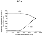
- Fig. 4 is a graph showing magnifications of gray scales after gain conversion in separate gain converter 1260 with respect to those before the conversion. This graph shows that the gain magnifications are determined on the basis of the gray scales before the conversion.
- the abscissa axis shows gray scales before the conversion at a gray scale accuracy of 10 bits.
- the ordinate axis shows magnifications of gray scales after the conversion with respect to those before the conversion.
- the conversion characteristics include the following two types: gain characteristics 4010 and gain characteristics 4020. These conversion characteristics are derived from the magnifications of the gray scale values after the conversion with respect to the gray scales before the conversion in the conventional gamma conversion characteristics of Fig. 9 .
- Magnification operation part 1250 selects the maximum gray scale value of the supplied RGB subframe signals and outputs magnifications corresponding to the selected value. For example, assume that RGB subframe signal levels are 900, 600, and 250, respectively. RGB subframe signal levels of 900, 600, and 250 indicate that the R signal level is 900, the G signal level is 600, and the B signal level is 250. In this case, magnification operation part 1250 outputs two types of magnifications corresponding to the maximum value, i.e. an R signal value of 900. These magnifications are 1.14 according to gain characteristics 4010 and 0.84 according to gain characteristics 4020.
- Separate gain converter 1260 applies the gains to the supplied subframe signals, using the information on the two types of gain magnifications from magnification operation part 1250, and outputs two sets of subframe signals.
- Selection circuit 1230 selects either one of the two sets of the RGB subframe signals from separate gain converter 1260, according to the determination result of frame determination part 1240. For example, when frame determination part 1240 determines that the data in the first subframe is supplied, selection circuit 1230 selects the first set of the output from separate gain converter 1260 (gain converter Ra 1261, gain converter Ga 1262, and gain converter Ba 1263). When frame determination part 1240 determines that the data in the second subframe is supplied, selection circuit 1230 selects the second set of the output from separate gain converter 1260 (gain converter Rb 1264, gain converter Gb 1265, and gain converter Bb 1266).
- image signals in two subframes each having a cycle equal to a half of that of an image signal in the original one frame (having a frequency of 60 Hz) are subjected to bright and dark gain conversions of Fig. 4 , and the converted signals are alternately supplied.
- the signals approximating those of the impulse driving in a pseudo manner substantially similar to the conventional example of Fig. 10B are supplied from selection circuit 1230. Further, application of the same magnifications to the three colors can eliminate color deviation between the subframes.
- driver circuit 1320 drives LCD panel 1310 to display an image on LCD panel 1310.
- this structure allows display approximating that provided by impulse driving, and eliminates the color deviation between the subframes.
- any color excluded from the original signals of a moving image is not added to the contours thereof, and an excellent image can be displayed.
- Fig. 1 also shows a block diagram of an essential structure of an image display device in accordance with the second exemplary embodiment of the present invention.
- the structure of this embodiment is similar to that of the first exemplary embodiment, and the description thereof is omitted.
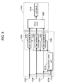
- Fig. 3 is a block diagram further detailing the internal structure of liquid crystal display (LCD) driver 1300 and gamma gain converter 1200 in the second exemplary embodiment.
- LCD liquid crystal display
- driver circuit 1320 drives LCD panel 1310, i.e. a display device.
- Magnification switch part 1270 determines from which subframe a data is supplied, according to a synchronization signal or frame information signal 1208, and switches the gain magnifications to be applied to RBG subframe signals, according to the subframe signal.
- Directly-connected separate gain converter 1280 applies a gain to the RGB subframe signals, and outputs the result.
- the image signal is further preprocessed in the previous stage of Fig. 1 .
- the drawing and the description of the structure of the previous stage are omitted.
- the subframe signals to be fed into gamma gain converter 1200 include R signal 1205, G signal 1206, and B signal 1207. These RGB subframe signals are fed into magnification switch part 1270 and directly-connected separate gain converter 1280.
- Magnification switch part 1270 selects the maximum gray scale value of the supplied RGB subframe signals and alternately outputs two types of magnifications corresponding to the maximum value, according to the order of the subframes.
- Directly-connected gain converter 1280 includes gain converter R1281, gain converter G1282, and gain converter B1283. Directly-connected separate gain converter 1280 alternately applies the gains according to the order of the subframes to the supplied subframe signals, using the information on the two types of gain magnifications from magnification switch part 1270, and supplies one set of RGB subframe output at the same time.
- signals in two subframes each having a cycle equal to a half of that of an image signal in the original one frame (having a frequency of 60 Hz) are subjected to bright and dark gain conversions of Fig. 4 , and the converted signals are alternately supplied.
- the signals approximating those of the impulse driving in a pseudo manner substantially similar to the conventional example of Fig. 10B are supplied from selection circuit 1230. Further, application of the same magnifications to the three colors can eliminate color deviation between the subframes.
- the subframe signals supplied from directly-connected separate gain converter 1280 in gamma gain converter 1200 are fed into driver circuit 1320 in LCD driver 1300.
- Driver circuit 1320 drives LCD panel 1310 to display an image on LCD panel 1310.
- this structure allows display approximating that provided by impulse driving and eliminates the color deviation between the subframes.
- any color excluded from the original signals of a moving image is not added to the contours thereof, and an excellent image can be displayed.
- Fig. 5 is a block diagram of an essential structure of an image display device in accordance with the third exemplary embodiment of the present invention.
- image signal 1301 is supplied to frame rate converter 1100.
- Frame rate converter 1100 converts the frame rate of image signal 1301, from a frame to a subframe having a double frequency, for example.
- Gamma converter 1400 converts the output of frame rate converter 1100 so that an image to be displayed on a liquid crystal display (LCD) has predetermined gamma characteristics.
- LCD driver 1300 drives the LCD.
- the LCD is an example of a display device.
- RGB level detector 1500 detects the maximum level of the RGB of image signal 1301, and outputs gamma switching signal 1501 to gamma converter 1400.
- Fig. 6 further details the internal structure of LCD driver 1300 and gamma converter 1400 of Fig. 5 .
- driver circuit 1320 drives LCD panel 1310, i.e. a display device.
- Frame determination part 1440 determines from which subframe a signal is supplied, according to a synchronization signal or frame information signal 1404, and outputs the result.
- gamma switch part 1490 calculates or selects two types of gamma conversion tables to be applied to the image signal.
- Separate gamma converter 1410 gamma-converts the RGB subframe signals using the gamma conversion tables supplied from gamma switch part 1490, and outputs the results.
- Selection circuit 1430 selects either one of the two sets of the subframe signals from separate gamma converter 1410, according to the result supplied from frame determination part 1440.
- the image signal is further preprocessed in the previous stage of Fig.5 .
- the drawing and the description of the structure of the previous stage are omitted.
- the image signal is also fed into RGB level detector 1500, where the maximum value of the RGB is detected.
- RGB level detector 1500 further generates gamma switching signal 1501 corresponding to the maximum level, and controls gamma converter 1400.
- Gamma switching signal 1501 varies with the magnitude of the maxim level detected in RGB level detector 1500.
- a description is provided of the subframe signals fed into gamma converter 1400, with reference to Fig. 6 .
- the elements denoted with the same reference marks as those in Fig. 2 have the same functions, and thus the elements different from those in Fig. 2 are mainly described.
- a synchronization signal or frame information signal 1404 is supplied together with the RGB subframe signals.
- the frame information signal refers to an information signal showing from which subframe a data is supplied when a frame is divided into two subframes.
- frame determination part 1440 determines from which subframe a data is supplied, and informs selection circuit 1430 of the result.
- R signal 1401, G signal 1402, and B signal 1403 fed into gamma converter 1400 are fed into separate gamma converter 1410.
- Gamma switch part 1490 switches the gamma conversion characteristics tables to be applied to the image signals in separate gamma converter 1410, according to gamma switching signal 1501 from RGB level detector 1500 of Fig. 5 . A description is provided of this switching of gamma conversion characteristics, with reference to Fig. 8 .
- Fig. 8 is a graph showing characteristics of gray scales after gamma conversion in separate gamma converter 1410 with respect to those before the conversion.
- the abscissa axis shows gray scales before the conversion at a gray scale accuracy of 10 bits.
- the ordinate axis shows gray scales after the conversion at a gray scale accuracy of 10 bits.
- the conversion characteristics include the following two types: gamma conversion characteristics (a) 8010, and gamma conversion characteristics (b) 8020.
- Gamma conversion characteristics (a) 8010 further include gamma conversion characteristics 8011, gamma conversion characteristics 8012, and gamma conversion characteristics 8013 having different conversion levels.
- Gamma conversion characteristics (b) 8020 include gamma conversion characteristics 8021, gamma conversion characteristics 8022, and gamma conversion characteristics 8023.
- the gamma switching signal varies with the magnitude of the maxim level detected in RGB level detector 1500.
- Gamma switch part 1490 selects and outputs a gamma conversion characteristics table having the lower conversion level, for a gamma switching signal having the higher maxim level.
- gamma conversion characteristics 8013 and gamma conversion characteristics 8023 are such examples.
- gamma switch part 1490 selects and outputs a gamma conversion characteristics table having the higher conversion level.
- gamma conversion characteristics 8011 and gamma conversion characteristics 8021 are such examples.
- Separate gamma converter 1410 gamma-converts the supplied subframe signals using the two types of gamma conversion characteristics tables supplied from gamma switch part 1490, and supplies two sets of RGB subframe output.
- Selection circuit 1430 selects either one of the two sets of the RGB output from separate gamma converter 1410, according to the determination result from frame determination part 1440. For example, when frame determination part 1440 determines that the data in the first subframe is supplied, selection circuit 1430 selects the first set of the RBG output from separate gamma converter 1410 (gamma converter Ra 1411, gamma converter Ga 1412, and gamma converter Ba 1413). When frame determination part 1440 determines that the data in the second subframe is supplied, selection circuit 1430 selects the second set of the RBG output from separate gamma converter 1410 (gamma converter Rb 1414, gamma converter Gb 1415, and gamma converter Bb 1416).
- image signals in two subframes each having a cycle equal to a half of that of an image signal in the original one frame (having a frequency of 60 Hz) are subjected to bright and dark gamma conversions of Fig. 8 , and the converted signals are alternately supplied.
- the signals approximating those of the impulse driving in a pseudo manner substantially similar to the conventional example of Fig. 10B are supplied from selection circuit 1430.
- the gamma conversion level is lower for an image signal that includes RGB color signals having the higher maxim signal level.
- the difference between the gamma conversions to be applied to the two subframes is small. As a result, color deviation between the subframes can be eliminated.
- driver circuit 1320 drives LCD panel 1310 to display an image on LCD panel 1310.
- this structure allows display approximating that provided by impulse driving, and eliminates the color deviation between the subframes.
- any color excluded from the original signals of a moving image is not added to the contours thereof, and an excellent image can be displayed.
- Fig. 5 also shows a block diagram of an essential structure of an image display device in accordance with the fourth exemplary embodiment of the present invention.
- the structure of this exemplary embodiment is similar to that of the third exemplary embodiment, and thus the description of the structure is omitted.
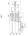
- Fig. 7 further details the internal structure of liquid crystal display (LCD) driver 1300 and gamma converter 1400 in the fourth exemplary embodiment.
- LCD liquid crystal display
- driver circuit 1320 drives LCD panel 1310, i.e. a display device.
- Gamma synchronization switch part 1417 determines from which subframe a data is supplied, according to a synchronization signal or frame information signal 1409, and switches gamma conversion tables, corresponding to the subframe.
- Directly-connected separate gamma converter 1418 gamma-converts RGB image signals, using a gamma conversion table from gamma synchronization switch part 1417, and outputs the result.
- the image signal is further preprocessed in the previous stage of Fig. 5 .
- the drawing and the description of the structure of the previous stage are omitted.
- a synchronization signal or frame information signal 1409 is supplied together with the RGB subframe image signals.
- the frame information signal refers to an information signal showing from which subframe a data is supplied when a frame is divided into two subframes.
- gamma synchronization switch part 1417 determines from which subframe a data is supplied.
- RGB subframe signals fed into gamma converter 1400 are fed into directly-connected separate gamma converter 1418.
- Gamma synchronization switch part 1417 switches the gamma conversion characteristics tables to be applied to the image signals in directly-connected separate gamma converter 1418, according to a gamma switching signal from RGB level detector 1500 of Fig. 5 .
- Fig. 8 is a drawing for explaining this switching of gamma conversion characteristics. The description of Fig. 8 is provided in the third exemplary embodiment, and thus is omitted in this exemplary embodiment.
- the gamma switching signal varies with the magnitude of the maxim level detected in RGB level detector 1500.
- gamma synchronization switch part 1417 selects and outputs a gamma conversion characteristics table having the lower conversion level, for a gamma switching signal having the higher maxim level.
- gamma conversion characteristics 8013 and gamma conversion characteristics 8023 are such examples.
- gamma synchronization switch part 1417 selects and outputs a gamma conversion characteristics table having the higher conversion level.
- gamma conversion characteristics 8011 and gamma conversion characteristics 8021 are such examples.
- gamma synchronization switch part 1417 determines from which subframe a data is supplied, and alternately outputs two types of tables including gamma conversion characteristics (a) 8010 and gamma conversion characteristics (b) 8020, according to the order of the subframes. For example, gamma conversion characteristics 8011 is supplied for the first subframe and gamma conversion characteristics 8023 is supplied for the second subframe.
- Directly-connected gamma converter 1418 gamma-converts the supplied subframe signals, alternately using the two types of gamma conversion characteristics tables supplied from gamma synchronization switch part 1417, according to the order of the subframes, and supplies one set of RGB subframe output at the same time.
- image signals in two subframes each having a cycle equal to a half of that of an image signal in the original one frame (having a frequency of 60 Hz) are subjected to bright and dark gamma conversions of Fig. 8 , and the converted signals are alternately supplied.
- the signals approximating those of the impulse driving in a pseudo manner substantially similar to the conventional example of Fig. 10B are supplied.
- the gamma conversion level is lower when the maxim signal level of an R signal, a G signal, and a B signal is higher.
- the difference between the gamma conversions to be applied to the two subframes is small. As a result, color deviation between the subframes can be eliminated.
- the image signals supplied from directly-connected separate gamma converter 1418 in gamma converter 1400 are fed into driver circuit 1320 in LCD driver 1300.
- Driver circuit 1320 drives LCD panel 1310 to display an image on LCD panel 1310.
- a frame is divided into subframes, and different gamma corrections are made to the respective subframes.
- Such corrections cause luminance information to be biased on one of the subframes.
- no color deviation occurs between the divided two frames (subframes).
- Such operation can offer a remarkable advantage of eliminating coloring in the contours of a moving halftone image while maintaining the white peak.
- this operation allows display approximating that provided by impulse driving, and eliminates the color deviation between the subframes.
- any color excluded from the original signals of a moving image is not added to the contours thereof, and an excellent image can be displayed.
- the image display device of the present invention has a remarkable advantage of improving the quality level of images without sacrificing the quality of moving images.
- the image display device is particularly useful as a display device in a television receiver or the like in which displaying moving images is important.
Landscapes
- Engineering & Computer Science (AREA)
- Physics & Mathematics (AREA)
- General Physics & Mathematics (AREA)
- Computer Hardware Design (AREA)
- Crystallography & Structural Chemistry (AREA)
- Chemical & Material Sciences (AREA)
- Theoretical Computer Science (AREA)
- Signal Processing (AREA)
- Multimedia (AREA)
- Nonlinear Science (AREA)
- Mathematical Physics (AREA)
- Optics & Photonics (AREA)
- Control Of Indicators Other Than Cathode Ray Tubes (AREA)
- Liquid Crystal Display Device Control (AREA)
- Transforming Electric Information Into Light Information (AREA)
Applications Claiming Priority (2)
| Application Number | Priority Date | Filing Date | Title |
|---|---|---|---|
| JP2006108427 | 2006-04-11 | ||
| PCT/JP2007/057942 WO2007119731A1 (ja) | 2006-04-11 | 2007-04-11 | 画像表示装置 |
Publications (2)
| Publication Number | Publication Date |
|---|---|
| EP1983507A1 true EP1983507A1 (de) | 2008-10-22 |
| EP1983507A4 EP1983507A4 (de) | 2010-03-24 |
Family
ID=38609491
Family Applications (1)
| Application Number | Title | Priority Date | Filing Date |
|---|---|---|---|
| EP07741378A Withdrawn EP1983507A4 (de) | 2006-04-11 | 2007-04-11 | Bildanzeigevorrichtung |
Country Status (6)
| Country | Link |
|---|---|
| US (1) | US20090058778A1 (de) |
| EP (1) | EP1983507A4 (de) |
| JP (1) | JPWO2007119731A1 (de) |
| KR (1) | KR101011596B1 (de) |
| CN (1) | CN101421774A (de) |
| WO (1) | WO2007119731A1 (de) |
Families Citing this family (4)
| Publication number | Priority date | Publication date | Assignee | Title |
|---|---|---|---|---|
| KR100943955B1 (ko) | 2008-06-18 | 2010-02-26 | 삼성모바일디스플레이주식회사 | 표시 장치 및 그의 구동 방법 |
| JP2011028107A (ja) * | 2009-07-28 | 2011-02-10 | Canon Inc | ホールド型画像表示装置及びその制御方法 |
| EP3281249A4 (de) * | 2015-04-08 | 2018-12-26 | Fractal Antenna Systems Inc. | Leserantennen mit fraktaler plasmonischer oberfläche |
| US10714003B1 (en) * | 2019-01-03 | 2020-07-14 | Himax Technologies Limited | Image processing method and image processing system |
Family Cites Families (6)
| Publication number | Priority date | Publication date | Assignee | Title |
|---|---|---|---|---|
| WO1995001701A1 (en) | 1993-06-30 | 1995-01-12 | Philips Electronics N.V. | Matrix display systems and methods of operating such systems |
| JP3660610B2 (ja) * | 2001-07-10 | 2005-06-15 | 株式会社東芝 | 画像表示方法 |
| AU2003208464A1 (en) * | 2002-04-12 | 2003-10-27 | Cursor Controls Limited | Improved pointing device |
| JP4079793B2 (ja) * | 2003-02-07 | 2008-04-23 | 三洋電機株式会社 | 表示方法、表示装置およびそれに利用可能なデータ書込回路 |
| JP4341839B2 (ja) * | 2003-11-17 | 2009-10-14 | シャープ株式会社 | 画像表示装置、電子機器、液晶テレビジョン装置、液晶モニタ装置、画像表示方法、表示制御プログラムおよび記録媒体 |
| JP2005173387A (ja) * | 2003-12-12 | 2005-06-30 | Nec Corp | 画像処理方法、表示装置の駆動方法及び表示装置 |
-
2007
- 2007-04-11 US US12/296,259 patent/US20090058778A1/en not_active Abandoned
- 2007-04-11 EP EP07741378A patent/EP1983507A4/de not_active Withdrawn
- 2007-04-11 KR KR1020087023761A patent/KR101011596B1/ko not_active Expired - Fee Related
- 2007-04-11 CN CNA2007800132583A patent/CN101421774A/zh active Pending
- 2007-04-11 WO PCT/JP2007/057942 patent/WO2007119731A1/ja not_active Ceased
- 2007-04-11 JP JP2008510955A patent/JPWO2007119731A1/ja not_active Withdrawn
Also Published As
| Publication number | Publication date |
|---|---|
| JPWO2007119731A1 (ja) | 2009-08-27 |
| EP1983507A4 (de) | 2010-03-24 |
| WO2007119731A1 (ja) | 2007-10-25 |
| US20090058778A1 (en) | 2009-03-05 |
| KR20080105128A (ko) | 2008-12-03 |
| CN101421774A (zh) | 2009-04-29 |
| KR101011596B1 (ko) | 2011-01-27 |
Similar Documents
| Publication | Publication Date | Title |
|---|---|---|
| JP4768344B2 (ja) | 表示装置 | |
| US7227521B2 (en) | Image display apparatus | |
| KR100758295B1 (ko) | 감마 보정 장치 및 이를 구비한 디스플레이 장치 그리고그것의 감마 보정 방법 | |
| US20070109242A1 (en) | Liquid crystal display and driving method thereof | |
| US7995080B2 (en) | Image display apparatus | |
| US20100171776A1 (en) | Picture display device | |
| US7327333B2 (en) | Method and apparatus for reducing flicker when displaying pictures on a plasma display panel | |
| US20110025726A1 (en) | Hold-type image display apparatus and display method using the hold-type image display apparatus | |
| US8026934B2 (en) | Driving control apparatus of display apparatus, display method, display apparatus, display monitor, and television receiver | |
| JP2000221945A (ja) | マトリクス型表示装置 | |
| US20070273713A1 (en) | Driving a matrix display | |
| US20050017939A1 (en) | Display driver and image display method | |
| US20090058778A1 (en) | Image display device | |
| JP2011141557A (ja) | 表示装置 | |
| EP2009930A2 (de) | Bildanzeigevorrichtung | |
| US20080284881A1 (en) | Method and system for video motion blur reduction | |
| KR100432666B1 (ko) | 플라즈마 디스플레이 패널의 구동장치 및 구동방법 | |
| JP2000352701A (ja) | 液晶装置における画像表示方法 | |
| KR20060047960A (ko) | 거짓윤곽경감장치, 표시장치, 거짓윤곽경감방법, 및거짓윤곽경감 프로그램 | |
| US20040227712A1 (en) | Image processing method, image processing apparatus, and liquid crystal display using same | |
| KR101252841B1 (ko) | 데이터 변환 장치, 그 방법 및 이를 구비한 액정표시장치 | |
| JPH10105108A (ja) | カラー画像表示装置 | |
| KR100965577B1 (ko) | 액정표시장치 및 이의 구동방법 | |
| JPH08317321A (ja) | 画像表示装置 | |
| JP2005070652A (ja) | 画像表示装置 |
Legal Events
| Date | Code | Title | Description |
|---|---|---|---|
| PUAI | Public reference made under article 153(3) epc to a published international application that has entered the european phase |
Free format text: ORIGINAL CODE: 0009012 |
|
| 17P | Request for examination filed |
Effective date: 20080825 |
|
| AK | Designated contracting states |
Kind code of ref document: A1 Designated state(s): GB |
|
| RAP1 | Party data changed (applicant data changed or rights of an application transferred) |
Owner name: PANASONIC CORPORATION |
|
| DAX | Request for extension of the european patent (deleted) | ||
| RBV | Designated contracting states (corrected) |
Designated state(s): GB |
|
| A4 | Supplementary search report drawn up and despatched |
Effective date: 20100223 |
|
| 17Q | First examination report despatched |
Effective date: 20100602 |
|
| STAA | Information on the status of an ep patent application or granted ep patent |
Free format text: STATUS: THE APPLICATION HAS BEEN WITHDRAWN |
|
| 18W | Application withdrawn |
Effective date: 20110316 |