EP1983516A2 - Zusammensetzung zur optischen Aufzeichnung und holografisches Aufzeichnungsmedium - Google Patents
Zusammensetzung zur optischen Aufzeichnung und holografisches Aufzeichnungsmedium Download PDFInfo
- Publication number
- EP1983516A2 EP1983516A2 EP08007651A EP08007651A EP1983516A2 EP 1983516 A2 EP1983516 A2 EP 1983516A2 EP 08007651 A EP08007651 A EP 08007651A EP 08007651 A EP08007651 A EP 08007651A EP 1983516 A2 EP1983516 A2 EP 1983516A2
- Authority
- EP
- European Patent Office
- Prior art keywords
- group
- recording
- optical recording
- denotes
- general formula
- Prior art date
- Legal status (The legal status is an assumption and is not a legal conclusion. Google has not performed a legal analysis and makes no representation as to the accuracy of the status listed.)
- Granted
Links
Images



Classifications
-
- G—PHYSICS
- G11—INFORMATION STORAGE
- G11B—INFORMATION STORAGE BASED ON RELATIVE MOVEMENT BETWEEN RECORD CARRIER AND TRANSDUCER
- G11B7/00—Recording or reproducing by optical means, e.g. recording using a thermal beam of optical radiation by modifying optical properties or the physical structure, reproducing using an optical beam at lower power by sensing optical properties; Record carriers therefor
- G11B7/24—Record carriers characterised by shape, structure or physical properties, or by the selection of the material
- G11B7/241—Record carriers characterised by shape, structure or physical properties, or by the selection of the material characterised by the selection of the material
- G11B7/242—Record carriers characterised by shape, structure or physical properties, or by the selection of the material characterised by the selection of the material of recording layers
- G11B7/244—Record carriers characterised by shape, structure or physical properties, or by the selection of the material characterised by the selection of the material of recording layers comprising organic materials only
-
- G—PHYSICS
- G11—INFORMATION STORAGE
- G11B—INFORMATION STORAGE BASED ON RELATIVE MOVEMENT BETWEEN RECORD CARRIER AND TRANSDUCER
- G11B7/00—Recording or reproducing by optical means, e.g. recording using a thermal beam of optical radiation by modifying optical properties or the physical structure, reproducing using an optical beam at lower power by sensing optical properties; Record carriers therefor
- G11B7/24—Record carriers characterised by shape, structure or physical properties, or by the selection of the material
- G11B7/241—Record carriers characterised by shape, structure or physical properties, or by the selection of the material characterised by the selection of the material
- G11B7/242—Record carriers characterised by shape, structure or physical properties, or by the selection of the material characterised by the selection of the material of recording layers
- G11B7/244—Record carriers characterised by shape, structure or physical properties, or by the selection of the material characterised by the selection of the material of recording layers comprising organic materials only
- G11B7/245—Record carriers characterised by shape, structure or physical properties, or by the selection of the material characterised by the selection of the material of recording layers comprising organic materials only containing a polymeric component
-
- G—PHYSICS
- G11—INFORMATION STORAGE
- G11B—INFORMATION STORAGE BASED ON RELATIVE MOVEMENT BETWEEN RECORD CARRIER AND TRANSDUCER
- G11B7/00—Recording or reproducing by optical means, e.g. recording using a thermal beam of optical radiation by modifying optical properties or the physical structure, reproducing using an optical beam at lower power by sensing optical properties; Record carriers therefor
- G11B7/007—Arrangement of the information on the record carrier, e.g. form of tracks, actual track shape, e.g. wobbled, or cross-section, e.g. v-shaped; Sequential information structures, e.g. sectoring or header formats within a track
- G11B7/00772—Arrangement of the information on the record carrier, e.g. form of tracks, actual track shape, e.g. wobbled, or cross-section, e.g. v-shaped; Sequential information structures, e.g. sectoring or header formats within a track on record carriers storing information in the form of optical interference patterns, e.g. holograms
- G11B7/00781—Auxiliary information, e.g. index marks, address marks, pre-pits, gray codes
-
- G—PHYSICS
- G11—INFORMATION STORAGE
- G11B—INFORMATION STORAGE BASED ON RELATIVE MOVEMENT BETWEEN RECORD CARRIER AND TRANSDUCER
- G11B7/00—Recording or reproducing by optical means, e.g. recording using a thermal beam of optical radiation by modifying optical properties or the physical structure, reproducing using an optical beam at lower power by sensing optical properties; Record carriers therefor
- G11B7/24—Record carriers characterised by shape, structure or physical properties, or by the selection of the material
- G11B7/2403—Layers; Shape, structure or physical properties thereof
- G11B7/24035—Recording layers
- G11B7/24044—Recording layers for storing optical interference patterns, e.g. holograms; for storing data in three dimensions [3D], e.g. volume storage
-
- G—PHYSICS
- G11—INFORMATION STORAGE
- G11B—INFORMATION STORAGE BASED ON RELATIVE MOVEMENT BETWEEN RECORD CARRIER AND TRANSDUCER
- G11B7/00—Recording or reproducing by optical means, e.g. recording using a thermal beam of optical radiation by modifying optical properties or the physical structure, reproducing using an optical beam at lower power by sensing optical properties; Record carriers therefor
- G11B7/24—Record carriers characterised by shape, structure or physical properties, or by the selection of the material
- G11B7/241—Record carriers characterised by shape, structure or physical properties, or by the selection of the material characterised by the selection of the material
- G11B7/242—Record carriers characterised by shape, structure or physical properties, or by the selection of the material characterised by the selection of the material of recording layers
- G11B7/244—Record carriers characterised by shape, structure or physical properties, or by the selection of the material characterised by the selection of the material of recording layers comprising organic materials only
- G11B7/249—Record carriers characterised by shape, structure or physical properties, or by the selection of the material characterised by the selection of the material of recording layers comprising organic materials only containing organometallic compounds
- G11B7/2492—Record carriers characterised by shape, structure or physical properties, or by the selection of the material characterised by the selection of the material of recording layers comprising organic materials only containing organometallic compounds neutral compounds
-
- G—PHYSICS
- G11—INFORMATION STORAGE
- G11B—INFORMATION STORAGE BASED ON RELATIVE MOVEMENT BETWEEN RECORD CARRIER AND TRANSDUCER
- G11B7/00—Recording or reproducing by optical means, e.g. recording using a thermal beam of optical radiation by modifying optical properties or the physical structure, reproducing using an optical beam at lower power by sensing optical properties; Record carriers therefor
- G11B7/24—Record carriers characterised by shape, structure or physical properties, or by the selection of the material
- G11B7/241—Record carriers characterised by shape, structure or physical properties, or by the selection of the material characterised by the selection of the material
- G11B7/252—Record carriers characterised by shape, structure or physical properties, or by the selection of the material characterised by the selection of the material of layers other than recording layers
- G11B7/253—Record carriers characterised by shape, structure or physical properties, or by the selection of the material characterised by the selection of the material of layers other than recording layers of substrates
- G11B7/2531—Record carriers characterised by shape, structure or physical properties, or by the selection of the material characterised by the selection of the material of layers other than recording layers of substrates comprising glass
-
- G—PHYSICS
- G11—INFORMATION STORAGE
- G11B—INFORMATION STORAGE BASED ON RELATIVE MOVEMENT BETWEEN RECORD CARRIER AND TRANSDUCER
- G11B7/00—Recording or reproducing by optical means, e.g. recording using a thermal beam of optical radiation by modifying optical properties or the physical structure, reproducing using an optical beam at lower power by sensing optical properties; Record carriers therefor
- G11B7/24—Record carriers characterised by shape, structure or physical properties, or by the selection of the material
- G11B7/241—Record carriers characterised by shape, structure or physical properties, or by the selection of the material characterised by the selection of the material
- G11B7/252—Record carriers characterised by shape, structure or physical properties, or by the selection of the material characterised by the selection of the material of layers other than recording layers
- G11B7/253—Record carriers characterised by shape, structure or physical properties, or by the selection of the material characterised by the selection of the material of layers other than recording layers of substrates
- G11B7/2533—Record carriers characterised by shape, structure or physical properties, or by the selection of the material characterised by the selection of the material of layers other than recording layers of substrates comprising resins
-
- G—PHYSICS
- G11—INFORMATION STORAGE
- G11B—INFORMATION STORAGE BASED ON RELATIVE MOVEMENT BETWEEN RECORD CARRIER AND TRANSDUCER
- G11B7/00—Recording or reproducing by optical means, e.g. recording using a thermal beam of optical radiation by modifying optical properties or the physical structure, reproducing using an optical beam at lower power by sensing optical properties; Record carriers therefor
- G11B7/24—Record carriers characterised by shape, structure or physical properties, or by the selection of the material
- G11B7/241—Record carriers characterised by shape, structure or physical properties, or by the selection of the material characterised by the selection of the material
- G11B7/252—Record carriers characterised by shape, structure or physical properties, or by the selection of the material characterised by the selection of the material of layers other than recording layers
- G11B7/253—Record carriers characterised by shape, structure or physical properties, or by the selection of the material characterised by the selection of the material of layers other than recording layers of substrates
- G11B7/2533—Record carriers characterised by shape, structure or physical properties, or by the selection of the material characterised by the selection of the material of layers other than recording layers of substrates comprising resins
- G11B7/2534—Record carriers characterised by shape, structure or physical properties, or by the selection of the material characterised by the selection of the material of layers other than recording layers of substrates comprising resins polycarbonates [PC]
-
- G—PHYSICS
- G11—INFORMATION STORAGE
- G11B—INFORMATION STORAGE BASED ON RELATIVE MOVEMENT BETWEEN RECORD CARRIER AND TRANSDUCER
- G11B7/00—Recording or reproducing by optical means, e.g. recording using a thermal beam of optical radiation by modifying optical properties or the physical structure, reproducing using an optical beam at lower power by sensing optical properties; Record carriers therefor
- G11B7/24—Record carriers characterised by shape, structure or physical properties, or by the selection of the material
- G11B7/241—Record carriers characterised by shape, structure or physical properties, or by the selection of the material characterised by the selection of the material
- G11B7/252—Record carriers characterised by shape, structure or physical properties, or by the selection of the material characterised by the selection of the material of layers other than recording layers
- G11B7/253—Record carriers characterised by shape, structure or physical properties, or by the selection of the material characterised by the selection of the material of layers other than recording layers of substrates
- G11B7/2533—Record carriers characterised by shape, structure or physical properties, or by the selection of the material characterised by the selection of the material of layers other than recording layers of substrates comprising resins
- G11B7/2536—Record carriers characterised by shape, structure or physical properties, or by the selection of the material characterised by the selection of the material of layers other than recording layers of substrates comprising resins polystyrene [PS]
-
- G—PHYSICS
- G11—INFORMATION STORAGE
- G11B—INFORMATION STORAGE BASED ON RELATIVE MOVEMENT BETWEEN RECORD CARRIER AND TRANSDUCER
- G11B7/00—Recording or reproducing by optical means, e.g. recording using a thermal beam of optical radiation by modifying optical properties or the physical structure, reproducing using an optical beam at lower power by sensing optical properties; Record carriers therefor
- G11B7/24—Record carriers characterised by shape, structure or physical properties, or by the selection of the material
- G11B7/241—Record carriers characterised by shape, structure or physical properties, or by the selection of the material characterised by the selection of the material
- G11B7/252—Record carriers characterised by shape, structure or physical properties, or by the selection of the material characterised by the selection of the material of layers other than recording layers
- G11B7/258—Record carriers characterised by shape, structure or physical properties, or by the selection of the material characterised by the selection of the material of layers other than recording layers of reflective layers
- G11B7/2585—Record carriers characterised by shape, structure or physical properties, or by the selection of the material characterised by the selection of the material of layers other than recording layers of reflective layers based on aluminium
Definitions
- the present invention relates to an optical recording composition comprising a bicyclic cyclopropane derivative. More particularly, the present invention relates to an optical recording composition suited to the manufacturing of a holographic recording medium, particularly a volume holographic recording medium having a relatively thick recording layer. The present invention further relates to a holographic recording medium having a recording layer formed with the above optical recording composition.
- Holographic optical recording media based on the principle of the holograph have been developed. Recording of information on holographic optical recording media is carried out by superposing an informing light containing image information and a reference light in a recording layer comprised of a photosensitive composition to write an interference fringe thus formed in the recording layer. During the reproduction of information, a reference light is directed at a prescribed angle into the recording layer in which the information has been recorded, causing optical diffraction of the reference light by the interference fringe which has been formed, reproducing the informing light
- volume holography and, more particularly, digital volume holography, have been developed to practical levels for ultrahigh-density optical recording and have been garnering attention.
- Volume holography is a method of writing interference fringes three-dimensionally by also actively utilizing the direction of thickness of an optical recording medium. It is advantageous in that increasing the thickness permits greater diffraction efficiency and multiplexed recording increases the recording capacity.
- Digital volume holography is a computer-oriented holographic recording method in which the image data being recorded are limited to a binary digital pattern while employing a recording medium and recording system similar to those of volume holography, In digital volume holography, for example, image information such as an analog drawing is first digitized and then expanded into two-dimensional digital pattern information, which is recorded as image information.
- An aspect of the present invention provides for an optical recording composition suited to high-sensitivity digital volume holography with large storage capacity, and for a holographic recording medium permitting ultrahigh-density optical recording using the above optical recording composition.
- An aspect of the present invention relates to an optical recording composition
- an optical recording composition comprising a bicyclic cyclopropane derivative denoted by General Formula (1).
- R 1 denotes an alkylene group or arylene group
- R 2 denotes an alkyl group, aryl group, or heterocyclic group
- X denotes a divalent linking group selected from the group consisting of -COO-, -CONH-, -OCO-, -NH-, -O-, -S-, -CO-, -SO 2 -, -SO 3 -, and -SO 2 NH-
- n and m each independently denote an integer ranging from 0 to 8, with n+m being an integer ranging from 0 to 8
- Y denotes a divalent linking group selected from the group consisting of -CR 9 R 4 -, -O-, and -S-
- R 3 and R 4 each independently denote a hydrogen atom, alkyl group, aryl group, alkoxycarbonyl group, or aryloxycarbonyl group
- r denotes an integer ranging from 1 to 4, wherein there
- the bicyclic cyclopropane derivative denoted by General Formula (1) may be a bicyclic cyclopropane derivative denoted by General Formula (II).
- each of R 1 , R 2 , Y, n, m, and r is defined in the same manner as in General Formula (I).
- r may denote an integer ranging from 2 to 4.
- R 1 or R 2 may denote an aryl group
- the optical recording composition may further comprises a thermosetting compound.
- thermosetting compound may comprise a polyfunctional isocyanate and a polyfunctional alcohol.
- the optical recording composition may further comprises an optical radical polymerization initiator.
- the optical recording composition may be a holographic recording composition.
- a further aspect of the present invention relates to a holographic recording medium comprising a recording layer, wherein the recording layer is formed with the above optical recording composition.
- the holographic recording medium of the present invention permits ultrahigh-density recording and is particularly suited as a recording medium for digital volume holography permitting the use of inexpensive lasers and capable of reducing the time required for writing.
- the optical recording composition of the present invention comprises at least a bicyclic cyclopropane derivative denoted by General Formula (1), is preferably employed as a holographic recording composition, and is particularly suitable as a volume holographic recording composition.
- holographic recording is a method of recording information by superposing an informing light containing information and a reference light in a recording layer to write an interference fringe thus formed in the recording layer.
- Volume holographic recording is a method of recording information in holographic recording in which a three-dimensional interference image is written in the recording layer.
- R 1 denotes an alkylene group or arylene group
- R 2 denotes an alkyl group, aryl group, or heterocyclic group
- X denotes a divalent linking group selected from the group consisting of -COO-, -CONH-, -OCO-, -NH-, -O-, -S-, -CO-, -SO 2 -, -SO 3 -, and -SO 2 NH-
- n and m each independently denote an integer ranging from 0 to 8, with n+m being an integer ranging from 0 to 8
- Y denotes a divalent linking group selected from the group consisting of -CR 3 R 4 -, -O-, and -S-
- R 3 and R 4 each independently denote a hydrogen atom, alkyl group, aryl group, alkoxycarbonyl group, or aryloxycarbonyl group
- r denotes an integer ranging from 1 to 4, wherein there
- R 1 denotes an alkylene group or arylene group.
- the alkylene group denoted by R 1 may be linear or branched and may be substituted or unsubstituted. It preferably comprises 1 to 30 carbon atoms, more preferably 1 to 20 carbon atoms.
- Divalent functional groups may be present in the alkylene chain in such a manner as to not be mutually adjacent. Such divalent functional groups are preferably -O- and -S-, with -O- being more preferable.
- the arylene group denoted by R 1 in General Formula (I) may be substituted, with 6 to 30 carbon atoms being preferable and 6 to 20 carbon atoms being more preferable.
- Divalent functional groups may be present in the arylene chain in such a manner as to not be mutually adjacent. Such divalent functional groups are preferably -0- and -S-, with -O- being more preferable.
- R 2 denotes an alkyl group, aryl group, or heterocyclic group.
- the alkyl group denoted by R 2 in General Formula (I) may be linear or branched and may be substituted or unsubstituted. It preferably comprises 1 to 30 carbon atoms, more preferably 1 to 20 carbon atoms.
- alkyl groups are a methyl group, ethyl group, normal propyl group, isopropyl group, normal butyl group, isobutyl group, tertiary butyl group, pentyl group, cyclopentyl group, hexyl groups, cyclohexyl group, heptyl group, octyl group, tertiary octyl group, 2-ethylhexyl group, decyl group, dodecyl group, octadecyl group, 2,3-dibromopropyl group, adamantyl group, benzyl group, or 4-bromobenzyl group. These may be further substituted.
- the aryl group denoted by R 2 in General Formula (I) may be substituted or unsubstituted. It preferably comprises 6 to 30 carbon atoms, more preferably 6 to 20 carbon atoms. Examples are a phenyl group, naphthyl group, and anthranyl group. These may be further substituted.
- the heterocyclic group denoted by R 2 in General Formula (1) is preferably a heterocyclic group with 4 to 14 carbon atoms, more preferably 4 to 10 carbon atoms, and still more preferably, 5 carbon atoms.
- Specific examples of the heterocyclic group denoted by R 2 are a pyridine ring, piperazine ring, thiophene ring, pyrrole ring, imidazole ring, oxazole ring, and thiazole ring. These may be further substituted. Of these heterocycles, a pyridine ring is particularly preferable.
- R 1 and R 2 are preferably an aryl group.
- X denotes a divalent linking group selected from the group consisting of -COO-, -CONH-, -OCO-, -NH-, -O-, -S-, -CO-, -SO 2 -, -SO 3 -, and -SO 2 NH-, Of these, -COO-, -CONH-, -OCO-, -NH-, -O-, -S-, and -CO- are preferable, and -COO- is more preferable.
- n and m each independently denote an integer ranging from 0 to 8, with n+m being limited to an integer ranging from 0 to 8.
- n+m preferably denotes an integer ranging from 1 to 5, and more preferably, denotes 2.
- Y denotes a divalent linking group selected from the group consisting of -CR 3 R 4 -, -0-, and -S-, with -CR 3 R 4 - and -S- being preferable and -CR 3 R 4 - being more preferable.
- R 3 and R 4 each independently denote a hydrogen atom, alkyl group, aryl group, allxycarbonyl group, or aryloxycarbonyl group. Details regarding alkyl groups and aryl groups denoted by R 3 and R 4 are as set forth above for the alkyl group and aryl group denoted by R 2 ,
- alkoxycarbonyl groups denoted by R 3 and R 4 are methyloxycarbonyl groups, ethyloxycarbonyl groups, normal propyloxycarbonyl groups, isopropyloxycarbonyl groups, normal butyloxycarbonyl groups, isobutyloxycarbonyl groups, tertiary butyloxycarbonyl groups, pentyloxycarbonyl groups, cyclopentyloxycarbonyl groups, hexyloxycerbonyl groups, cyclohexyloxycarbonyl groups, heptyloxycarbonyl croups, octyloxycarbonyl groups, tertiary octyloxycarbonyl groups, 2-ethylhexyloxycarbonyl groups, decyloxycarbonyl groups, and dodecyloxyc4rbonyt groups. These may be further substituted.
- aryloxycarbonyl groups denoted by R 3 and R 4 are phenyloxycarbonyl groups, naphthyloxycarbonyl groups, and anthranyloxycarbonyl groups. These may be further substituted.
- Examples of the substituent optionally comprised in the group denoted by R 2 , R 3 , or R 4 are; a halogen atom, alkyl group, alkenyl group, alkoxy group, aryloxy group, alkylthio group, alkoxycarbonyl group, and aryloxycarbonyl group. Of these, a halogen atom, alkoxy group, or alkylthio group is particularly preferable.
- the bicyclic cyclopropane denoted by General Formula (I) is a polyfunctional compound when a bicyclic cyclopropane structure is linked as a substituent.
- r denotes an integer ranging from 1 to 4, preferably an integer ranging from 2 to 4, more preferably 2 or 3, and still more preferably, 2.
- General Formula (II) below is an example of a preferable embodiment of the bicyclic cyclopropane derivative denoted by General Formula (I).
- each of R 1 , R 2 , Y, n, m, and r is defined in the same manner as in General Formula (I), with the details such as preferable embodiments being as set forth above.
- each of R 2 , Y, n, m, and r is defined in the same manner as in General Formula (I), with the details such as the preferable embodiments being as set forth above.
- the optical recording composition of the present invention comprises at least one bicyclic cyclopropane derivative denoted by General Formula (1).
- a single bicyclic cyclopropane derivative denoted by General Formula (I) may be employed, or two or more such derivatives may be employed in combination,
- the content of the bicyclic cyclopropane derivative denoted by General Formula (I) in the optical recording composition of the present invention is not specifically limited and may be suitably selected based on the objective. 1 to 50 weight percent is preferable, 1 to 30 weight percent is more preferable, and 3 to 10 weight percent is of even greater preference.
- the bicyclic cyclopropane derivative denoted by General Formula (I) can function as a recording monomer in the optical recording composition of the present invention.
- the optical recording composition of the present invention may comprise an optical polymerization initiator in addition to the bicyclic cyclopropane derivative denoted by General Formula (I).
- the optical polymerization initiator is not specifically limited so long as it has sensitivity to the recording beam; an optical radical polymerization initiator, cationic polymerization initiator, or the like may be employed. From the viewpoint of the efficiency of the polymerization reaction, an optical radical polymerization initiator is preferable.
- optical radical polymerization initiators are: 2,2'-bis(o-chlorophenyl)-4,4',5,5'-tetraphenyl-1,1'-blimldazole, 2,4,6-tris(trichloromethyl)-1,3,5-triazine, 2,4-bis(trichloromethyl)-6-(p-methoxyphenylvinyl)-1,3,5-triazine, diphenyliodoniumtetrafluoroborate, diphenyliodoniumhexafluorophosphate, 4,4'-di-t-butyldiphenyliodoniumtetrafluoroborate, 4-diethylaminophenylbenzenediazoniumhexafluorophosphate, benzoin 2-hydroxy-2-methyl-1-phenylpropane-2-one, benzophenone, thioxanthone, 2,4,6-trimethylbenzoyl diphenylacyl phosphine oxide, triphen
- cationic polymerization initiators are: 2,4,6-tris(trichloromethyl)-1,3,5-triazine, 2,4-bis(trichloromethyl)-6-(p-methoxyphenylvinyl)-1,3,5-triazine, phenyliodonium tetrafluoroborate, diphenyliodonium hexafluorophosphate, 4,4'-di-t-butyidiphenyliodonium tetrafluoroborate, 4-diethylamlnophenylbenzenediazonium hexafluorophosphate, tetraethylammonium triphenylbutylborate, and diphenyl-4-phenylthiophenylsulfonium hexafluorophosphate.
- the content of the optical polymerization initiator in the optical recording composition of the present invention is preferably 0.01 to 5 weight percent, more preferably 1 to 3 weight percent.
- the recording layer of an optical recording medium normally comprises a polymer to hold the optical polymerization initiator and monomers related to the recording and storage, known as a matrix.
- the matrix can be employed for achieving enhanced coating properties, coating strength, and hologram recording characteristics.
- the optical recording composition of the present invention can comprise matrix forming components in the form of curing compounds, Thermosetting compounds and light-curing compounds employing catalysts and the like that cure when irradiated with light may be employed as these curing compounds. Thermosetting compounds are preferable.
- thermosetting matrix comprised in the recording layer is not specifically limited and may be suitably selected based on the objective.
- examples are urethane resins formed from isocyanate compounds and alcohol compounds; epoxy compounds formed from oxysilane compounds; melamine compounds; formalin compounds; ester compounds of unsaturated acids such as (meth)acrylic acid and itaconic acid; and polymers obtained by polymerizing amide compounds, Of these, polyurethane matrices formed from isocyanate compounds and alcohol compounds are preferable.
- three-dimensional polyurethane matrices formed from polyfunctional isocyanates and polyfunctional alcohols are particularly preferred. Specific examples of polyfunctional isocyanates and polyfunctional alcohols capable of forming polyurethane matrices are described below.
- polyfunctional isocyanates are: biscyclohexylmethane diisocyanate, hexamethylene diisocyanate, phenylene-1,3-diisocyanate, phenytene-1,4-diisoryanate, 1-methoxyphenylene-2,4-diisocyanate, 1-methylphenylena-2,4-diisocyanate, 2,4-tolylene diisocyanate, 2,6-tolylene diisocyanate, 1,3-xylylene diisocyanate, 1,4-xylylene diisocyanate, biphenylene-4,4'-diisoeyatrate, 3,3'-dimethoxybiphenylene-4,4'-diisocyanate, 3,3'-dimethylbiphenylene-4,4'-diisocyanate, diphenylmeuiane-2,4'-diisocyanate, diphenylmetime-4,4'--
- the above polyfunctional alcohols may be in the form of a single polyfunctional alcohol, or in the form of a mixture with other polyfunctional alcohols.
- these polyfunctional alcohols are: glycols such as ethylene glycol, triethylene glycol, diethylene glycol, polyethylene glycol, propylene glycol, polypropylene glycol, and neopentyl glycol; diols such as butanediol, pentanediol, hexanediol, heptanediol, and tetramethylene glycol; bisphenols; compounds in the form of these polyfunctional alcohols modified by polyethyleneoxy chains or polypropyleneoxy chains; and compounds in the form of these polyfunctional alcohols modified by polyethyleneoxy chains or polypropyleneoxy chains, such as glycerin, trimethylolpropane, butanetriol, pentanetriol, hexanetriol, docanetriol, and other triols.
- the content of the matrix-forming compound in the optical recording composition of the present invention is preferably 10 to 95 weight percent, more preferably 35 to 90 weight percent. When this content is equal to or greater than 10 weight percent, a stable interference image can be readily obtained, and when equal to or less than 95 weight percent, properties that are desirable from the perspective of diffraction efficiency can be obtained.
- Polymerization Inhibitors and oxidation inhibitors may be added to the optical recording composition of the present invention to improve the storage stability of the optical recording composition, as needed.
- polymerization inhibitors and oxidation inhibitors are: hydroquinone, p-benzoquinone, hydroquinone monomethyl ether, 2,6-ditert-butyl-p-cresol, 2,2'-methylenebis(4-methyl-6-tert-butylphenol), triphenylphosphite, trisnonylphenylphoshite, phenothiazine, and N-isopropyl-N'-phenyl-p-phenylenediamine.
- the quantity of polymerization Inhibitor or oxidation inhibitor added is preferably equal to or less than 3 weight percent of the total quantity of recording monomer. When the quantity added exceeds 3 weight percent, polymerization may slow down, and in extreme cases, ceases.
- a sensitizing dye may be added to the optical recording composition of the present invention.
- Known compounds such as those described in " Research Disclosure, Vol. 200, 1980, December , Item 20036 " and " Sensitizers” (pp. 160-163, Kodansha, ed, by K. Tokumaru and M. Okawara, 1987 ) and the like may be employed as sensitizing dyes.
- Specific examples of sensitizing dyes are: 3-ketocoumarin compounds described in Japanese Unexamined Patent Publication (KOKAI) Showa No. 58-15603 ; thiopyrilium salt described in Japanese Unexamined Patent Publication (KOKAI) Showa No.
- keto dyes such as coumarin (including ketocoumarin and sulfonocoumarin) dyes, merostyryl dyes, oxonol dyes, and hemioxonol dyes
- nonketo dyes such as nonketo polymethine dyes, triarylmethane dyes, xanthene dyes, anthracene dyes, rhodamine dyes, acrylidine dyes, aniline dyes, and azo dyes
- nonketo polymethine dyes such as azomethine dyes, cyanine dyes, carbocyanine dyes, dicarbocyanine dyes, tricarbocyanine dyes, hemicyanine dyes, and styryl dyes
- quinone imine dyes such as azomethine dyes, cyanine dyes, carbocyanine dyes, dicarbocyanine dyes, tricarbocyanine dyes, hemicyanine dyes, and s
- a photo-heat converting material can be incorporated into the optical recording composition of the present invention for enhancing the sensitivity of the recording layer formed with the optical recording composition.
- the photo-heat converting material is not specifically limited, and may be suitably selected based on the functions and properties desired.
- an organic dye or pigment is desirable for convenience during addition to the recording layer with the photopolymer and so as not to scatter incident light.
- infrared radiation-absorbing dyes are desirable.
- Such infrared radiation-absorbing dyes are not specifically limited, and may be suitably selected based on the objective.
- cationic dyes, complex-forming dyes, quinvne-bassd neutral dyes, and the like are suitable.
- the maximum absorption wavelength of the infrared radiation-absorbing dye preferably falls within a range of 600 to 1,000 nm, more preferably a range of 700 to 900 nm.
- the content of infrared radiation-absorbing dye in the optical recording composition of the present invention can be determined based on the absorbance at the wavelength of maximum absorbance in the infrared region in the recording medium formed with the optical recording composition of the present invention. This absorbance preferably falls within a range of 0.1 to 2.5, more preferably a range of 0.2 to 2.0.
- the optical recording composition of the present invention may comprise a component that can diffuse into the inverse direction with that of the polymerizable components in order to reduce the volume change at polymerization, or a compound having an acid cleavage configuration may be added to the holographic recording composition in addition to the polymers.
- the optical recording composition of the present invention can be employed as various holographic recording compositions capable of recording information when irradiated with a light containing information.
- it is suited to use as a volume holographic recording composition.
- the recording layer can be formed by casting when the viscosity of the optical recording composition is adequately low
- a dispenser can be employed to spread a recording layer on a lower substrate, and an upper substrate pressed onto the recording layer so as to cover it and spread it over the entire surface, thereby forming a recording medium.
- the holographic recording medium of the present invention comprises a recording layer formed with the optical recording composition of the present invention.
- the recording layer comprised of the optical recording composition of the present invention can be formed by the above-described method.
- the holographic recording medium of the present invention comprises the above recording layer (holographic recording layer), and preferably comprises a lower substrate, a filter layer, a holographic recording layer, and an upper substrate. As needed, it may comprise additional layers such as a reflective layer, filter layer, first gap layer, and second gap layer.
- the holographic recording medium of the present invention is capable of recording and reproducing information through utilization of the principle of the hologram.
- This may be a relatively thin planar hologram that records two-dimensional information or the like, or a volumetric hologram that records large quantities of information, such as three-dimensional images. It may be either of the transmitting or reflecting type. Since the holographic recording medium of the present invention is capable of recording high volumes of information, it is suitable for use as a volume holographic recording medium of which high recording density is demanded.
- the method of recording a hologram on the holographic recording medium of the present invention is not specifically limited; examples are amplitude holograms, phase holograms, blazed holograms, and complex amplitude holograms.
- a preferred method is the so-called "collinear method" in which recording of information in volume holographic recording regions is carried out by irradiating an informing light and a reference light onto a volume holographic recording area as coaxial beams to record information by means of interference pattern through interference of the informing light and the reference light.
- the substrate is not specifically limited in terms of its shape, structure, size, or the like; these may be suitably selected based on the objective.
- the substrate may be disk-shaped, card-shaped, or the like.
- a substrate of a material capable of ensuring the mechanical strength of the holographic recording medium can be suitably selected.
- resin is particularly suitable.
- resins are: polycarbonate resin, acrylic resin, epoxy resin, polystyrene resin, acrylonitrile - styrene copolymers, polyethylene resin, polypropylene resin, silicone resin, fluorine resin, ABS resin, and urethane resin.
- polycarbonate resin and acrylic resin are preferred. Synthesized resins and commercially available resins may both be employed as substrates.
- address servo areas are provided on the substrate at prescribed angular intervals as multiple positioning areas extending linearly in a radial direction, with the fan-shaped intervals between adjacent address servo areas serving as data areas.
- Focus servo operation can be conducted using the reflective surface of a reflective film. Wobble pits, for example, can be employed as information for operating a tracking servo.
- the holographic recording medium is card-shaped, it is possible not to have a servo pit pattern.
- the thickness of the substrate is not specifically limited, and may be suitably selected based on the objective: a thickness of 0.1 to 5 mm is preferable, with 0.3 to 2 mm being preferred.
- a substrate thickness of equal to or greater than 0.1 mm is capable of preventing shape deformation during disk storage, while a thickness of equal to or less than 5 mm can avoid an overall disk weight generating an excessive load on the drive motor.
- the recording layer can be formed with the optical recording composition of the present invention and is capable of recording Information by holography.
- the thickness of the recording layer is not specifically limited, and may be suitably selected based on the objective. A recording layer thickness falling within a range of 1 to 1,000 micrometers yields an adequate S/N ratio even when conducting 10 to 300 shift multiplexing, and a thickness falling within a range of 100 to 700 micrometers is advantageous in that it yields a markedly good S/N ratio.
- a reflective film can be formed on the servo pit pattern surface of the substrate.
- a material having high reflectance for the informing light and reference light is preferably employed as the material of the reflective film.
- desirable materials are Al, Al alloys, Ag, and Ag alloys.
- the wavelength of the light employed as the informing light and reference light is equal to or greater than 650 nm, examples of desirable materials are Al, Al alloys, Ag, Ag alloys, Au, Cu alloys, and TiN.
- an optical recording medium that reflects light as well as can be recorded and/or erased information such as a DVD (digital video disk) as a reflective film
- record and rewrite directory information such as the areas in which holograms have been recorded, when rewriting was conducted, and the areas in which errors are present and for which alternate processing has been conducted, without affecting the hologram.
- the method of forming the reflective film is not specifically limited and may be suitably selected based on the objective.
- Various vapor phase growth methods such as vacuum deposition, sputtering, plasma CVD, optical CVD, ion plating, and electron beam vapor deposition may be employed. Of these, sputtering is superior from the perspectives of mass production, film quality, and the like.
- the thickness of the reflective film is preferably equal to or greater than 50 nm, more preferably equal to or greater than 100 nm, to obtain adequate reflectance.
- a filter layer can be provided on the servo pits of the substrate, on the reflective layer, or on the first gap layer, described further below.
- the filter layer has a function of reflecting selective wavelengths in which, among multiple light rays, only light of a specific wavelength is selectively reflected, permitting passing one light and reflecting a second light. It also has a function of preventing generation of noise in which irregular reflection of the informing light and the reference light by the reflective film of the recording medium is prevented without a shift in the selectively reflected wavelength even when the angle of incidence varies. Therefore, by stacking filter layers on the recording medium, it is possible to perform optical recording with high resolution and good diffraction efficiency.
- the filter layer is not specifically limited and may be suitably selected based on the objective.
- the filter layer can be comprised of a laminate in which at least one of a dichroic mirror layer, coloring material-containing layer, dielectric vapor deposition layer, single-layer or two- or more layer cholesteric layer and other layers suitably selected as needed is laminated.
- the thickness of the filter layer is not specifically limited and may be, for example, about 0.5 to 20 micrometers.
- the filter layer may be laminated by direct application on the substrate or the like with the recording layer, or may be laminated on a base material such as a film to prepare a filter layer which is then laminated on the substrate.
- the first gap layer is formed as needed between the filter layer and the reflective film to flatten the surface of the lower substrate. It is also effective for adjusting the size of the hologram that is formed in the recording layer. That is, since the recording layer should form a certain size of the interference region of the recording-use reference light and the informing light, it is effective to provide a gap between the recording layer and the servo pit pattern.
- the first gap layer can be formed by applying a material such as an ultraviolet radiation-curing resin from above the servo pit pattern and curing it.
- a material such as an ultraviolet radiation-curing resin from above the servo pit pattern and curing it.
- the transparent base material can serve as the first gap layer.
- the thickness of the first gap layer is not specifically limited, and can be suitably selected based on the objective. A thickness of 1 to 200 micrometers is desirable.
- the second gap layer is provided as needed between the recording layer and the filter layer.
- the material of the second gap layer is not specifically limited, and may be suitably selected based on the objective. Examples are: transparent resin films such as triacetyl cellulose (TAC), polycarbonate (PC), polyethylene terephthalate (PET), polystyrene (PS), polysulfone (PSF), polyvinylalcohol (PVA), and poly(methyl methacrylate) (PMMA); and norbornene resin films such as a product called ARTON film made by JSR Corporation and a product called Zeonoa made by Japan Zeon Co. Of these, those that are highly isotropic are desirable, with TAC, PC, the product called ARTON, and the product called Zeonoa being preferred.
- the thickness of the second gap layer is not specifically limited and may be suitably selected based on the objective. A thickness of 1 to 200 micrometers is desirable. Specific embodiments of the holographic recording medium of the present invention will be described in greater detail below. However, the present invention is not limited to these specific embodiments.
- Fig. 1 is a schematic cross-sectional view of the configuration of the holographic recording medium according to the first implementation embodiment.
- a servo pit pattern 3 is formed on substrate 1 made of polycarbonate resin or glass, and aluminum, gold, platinum, or the like is coated on servo pit pattern 3 to provide reflective film 2.
- servo pit pattern 3 has been formed over the entire surface of lower substrate 1, but the servo pit pattern may be formed cyclically.
- Servo pit pattern 3 is normally 1,750 Angstroms (175 nm) in height, and is quite small relative to the thickness of the substrate and the other layers.
- First gap layer 8 is formed by spin coating or the like a material such as an ultraviolet radiation-curing resin on reflective film 2 of lower substrate 1.
- First gap layer 8 is effective for both the protection of reflective layer 2 and the adjustment of the size of the hologram formed in recording layer 4. That is, providing a gap between recording layer 4 and servo pit pattern 3 is effective for the formation of an interference area for the recording ⁇ use reference light and informing light of a certain size in recording layer 4.
- Filter layer 6 is provided on first gap layer 8.
- Recording layer 4 is sandwiched between filter layer 6 and upper substrate 5 (a polycarbonate resin substrate or glass substrate) to form holographic recording medium 21.
- Fig. 1 shows a filter layer 6 that passes only infrared radiation and blocks light of all other colors. Accordingly, since the informing light and recording and reproducing-use reference light are blue, they are blocked by filter layer 6 and do not reach reflective film 2. They return, exiting from entry and exit surface A.
- Filter layer 6 is a multilayered vapor deposition film comprised of high refractive index layers and low refractive index layers deposited in alternating fashion. Filter layer 6, comprised of a multilayered vapor deposition film, may be formed directly on first gap layer 8 by vacuum vapor deposition, or a film comprised of a multilayered vapor deposition film formed on a base material may be punched into the shape of a holographic recording medium to employed as filter layer 6.
- holographic recording medium 21 may be disk-shaped or card-shaped. When card-shaped, the servo pit pattern may bo absent.
- the lower substrate is 0.6 mm
- first gap layer 8 is 100 micrometers
- filter layer 6 is 2 to 3 micrometers
- recording layer 4 is 0.6 mm
- upper substrate 5 is 0.6 mm in thickness, for a total thickness of about 1.9 mm.
- a light (red light) emitted by a servo laser is nearly 100 percent reflected by dichroic mirror 13, passing through objective lens 12.
- Objective lens 12 directs the servo light onto holographic recording medium 21 so that it focuses at a point on reflective film 2.
- dichroic mirror 13 passes light of green and blue wavelengths while reflecting nearly 100 percent of red light
- the returning light that exits passes through objective lens 12, is nearly 100 percent reflected by dichroic mirror 13, and the servo information is detected by a servo information detector (not shown in Fig. 3 ).
- the servo information that is detected is employed for focus servo, tracking servo, slide servo, and the like.
- the servo light passes through recording layer 4 without affecting recording layer 4, even when the servo light is randomly reflected by reflective film 2. Since the light in the form of the servo light reflected by reflective film 2 is nearly 100 percent reflected by dichroic mirror 13, the servo light is not detected by a CMOS sensor or CCD 14 for reproduction image detection and thus does not constitute noise to the reproduction light.
- the informing light and recording-use reference light generated by the recording/reproducing laser passes through polarizing plate 16 and is linearly polarized. It then passes through half mirror 17, becoming circularly polarized light at the point where it passes through 1/4 wavelength plate 15. The light then passes through dichroic mirror 13, and is directed by objective lens 12 onto holographic recording medium 21 so that the informing light and rocording-use reference light form an interference pattern In recording layer 4.
- the informing light and recording-use reference light enter through entry and exit surface A, interfering with each other to form an interference pattern In recording layer 4. Subsequently, the informing light and recording-use reference light pass through recording layer 4, entering filter layer 6. However, they are reflected before reaching the bottom surface of filter layer 6, returning.
- filter layer 6 is a multilayered vapor deposition layer in which multiple high refractive index and low refractive index layers are alternatively laminated, and has the property of passing only red light.
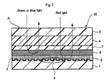
- Fig. 2 is a schematic cross-sectional view of the configuration of the holographic recording medium according to the second implementation embodiment.
- a servo pit pattern 3 is formed on substrate 1 made of polycarbonate resin or glass in the holographic recording medium 22 accoding to the second implementation embodiment.
- Reflective film 2 is provided by coating aluminum, gold, platinum, or the like on the surface of servo pit pattern 3.
- Servo pit pattern 3 is normally 1,750 Angstroms (175 nm) in height in the same manner as in the first implementation embodiment.
- the configuration of the second implementation embodiment differs from that of the first implementation embodiment in that second gap layer 7 is provided between filter layer 6 and recording layer 4 in holographic recording medium 22 according to the second implementation embodiment.
- a point at which the informing light and reproduction light are focused is present in second gap layer 7.
- this area is embedded in a photopolymer, excessive consumption of monomer occurs due to excess exposure, and multiplexing recording capability diminishes. Accordingly, it is effective to provide a nonreactive transparent second gap layer.
- Filter layer 6 in the form of a multilayered vapor deposition film comprised of multiple layers in which multiple high refractive index and low refractive index layers are alternately laminated is formed over first gap layer 8 once first gap layer 8 has been formed, and the same one as employed in the first implementation embodiment can be employed as filter layer 6 in the second implementation embodiment.
- lower substrate 1 is 1.0 mm
- first gap 8 is 100 micrometers
- filter layer 6 is 3 to 5 micrometers
- second gap layer 7 is 70 micrometers
- recording layer 4 is 0.6 mm
- upper substrate 5 is 0.4 mm in thickness, for a total thickness of about 2.2 mm.
- a red servo light and a green informing light and recording/reproducing reference light are directed onto holographic recording medium 22 of the second implementation embodiment having the configuration set forth above.
- the servo light enters through entry and exit surface A, passing through recording layer 4, second gap layer 7, filter layer 6, and first gap layer 8, and is reflected by reflective film 2, returning.
- the returning light then passes sequentially back through first gap layer 8, filter layer 6, second gap layer 7, recording layer 4, and upper substrate 5, exiting through entry and exit surface A.
- the returning light that exits is used for focus servo, tracking servo, and the like.
- the hologram material included in recording layer 4 is not sensitive to red light, the servo light passes through recording layer 4 and is randomly reflected by reflective film 2 without affecting recording layer 4.
- the green informing light and the like enters through entry and exit surface A, passing through recording layer 4 and second gap layer 7, and is reflected by filter layer 6, returning.
- the returning light then passes sequentially back through second gap layer 7, recording layer 4, and upper substrate 5, exiting through entry and exit layer A.
- the reproduction-use reference light and the reproduction light generated by irradiating the reproduction-use reference light onto recording layer 4 exit through entry and exit surface A without reaching reflective film 2.
- the optical action around holographic recording medium 22 is identical to that in the first implementation embodiment and thus the description thereof is omitted.
- An interference image can be formed on the recording layer formed with the optical recording composition of the present invention by irradiation of an informing light and a reference light to the recording layer, and a fixing light can be irradiated to the recording layer on which the interference image has been formed to fix the interference image.
- a light having coherent properties can be employed as the informing light.
- a informing light imparted with a two dimensional intensity distribution and a reference light of intensity nearly identical to that of the informing light are superposed in the recording layer and the interference pattern that they form is used to generate an optical characteristic distribution in the recording layer, thereby recording information.
- the wavelengths of the informing light and reference light are preferably equal to or greater than 400 nm, more preferably 400 to 2,000 nm, and further preferably, 400 to 700 nm.
- a fixing light After recording information (forming an interference image) by irradiating the informing light and reference light, a fixing light can be irradiated to fix the interference image.
- the wavelength of the fixing light is preferably less than 400 nm, more preferably equal to or greater than 100 nm but less than 400 nm, and further preferably, equal to or greater than 200 nm but less than 400 nm.
- Information can be reproduced by irradiating a reference light onto an interference image formed by the above-described method.
- a reference light is irradiated onto the recording layer with the same arrangement as during recording, causing a reproduction light having an intensity distribution corresponding to the optical characteristic distribution formed in the recording layer to exit the recording layer.
- the optical recording and reproducing device 100 of Fig. 4 is equipped with spindle 81 on which is mounted holographic recording medium 20, spindle motor 82 rotating spindle 81, and spindle servo circuit 83 controlling spindle motor 82 so that it maintains holographic recording medium 20 at a prescribed rpm level.
- Recording and reproducing device 100 is further equipped with pickup 31 for recording information by irradiating a informing light and a recording-use reference light onto holographic recording medium 20, and for reproducing information that has been recorded on holographic recording medium 20 by irradiating a reproducing-use reference light onto holographic recording medium 20 and detecting the reproduction light; and driving device 84 capable of moving pickup 31 radially with respect to holographic recording medium 20.
- Optical recording and reproducing device 100 is equipped with detection circuit 85 for detecting focus error signal FE, tracking error signal TE, and reproduction signal RF based on the output signals of pickup 31; focus servo circuit 86 that operates a focus servo by driving an actuator in pickup 31 to move an objective lens (not shown in Fig.
- tracking servo circuit 87 that operates a tracking servo by driving an actuator in pickup 31 to move an objective lens in the radial direction of holographic recording medium 20 based on tracking error signal TE detected by detection circuit 85
- slide servo circuit 88 that operates a slide servo by controlling drive device 84 to move pickup 31 In the radial direction of holographic recording medium 20 based on Instructions from a controller, described further below, and tracking error signal TE.
- Optical recording and reproducing device 100 is further equipped with signal processing circuit 89 that decodes the output data of a CCD array or CMOS in pickup 31 to reproduce data recorded in the data areas of holographic recording medium 20, reproduces a base clock based on reproduction signal RF from detection circuit 85, and determines addresses; controller 90 that effects overall control of optical recording and reproducing device 100; and operation element 91 providing various instructions to controller 90.
- Controller 90 inputs the base clock and address information outputted by signal processing circuit 89 and controls pickup 31, spindle servo circuit 83, slide servo circuit 88, and the like.
- Spindle servo circuit 83 inputs the base clock that is outputted by signal processing circuit 89.
- Controller 90 comprises a central processing unit (CPU), read only memory (ROM), and random access memory (RAM). The functions of controller 90 can be realized by having the CPU that employs the RAM as a work area and execute programs stored in the ROM.
- Example compounds M-14, M-16, M-19, and M-20 were synthesized by the scheme below according to the methods described in Macromol. Rapid Commun. 2003, 24, 269 ; Macrom. Mater. Eng. 2006, 291, 83 ; Adv. Synth. Catal. 2006, 348, 2133 .
- Example compound M-18 was employed instead of Example compound M-9 in Example 1, a holographic recording composition was prepared in the same manner as in Example 1.
- Example compound M-20 was employed instead of Example compound M-9 in Example 1, a holographic recording composition was prepared in the same manner as in Example 1.
- Example compound M-30 was employed instead of Example compound M-9 in Example 1
- a holographic recording composition was prepared in the same manner as in Example 1.
- Example compound M-16 was employed instead of Example compound M-9 in Example 1, a holographic recording composition was prepared in the same manner as in Example 1.
- optical polymerization initiator Irgacure 784, made by Chiba Specialty Chemicals
- a first substrate was prepared by subjecting one side of a glass sheet 0.5 mm in thickness to an antireflective treatment to impart a reflectance of 0.1 percent for perpendicularly incident light with the wavelength of 532 nm
- a second substrate was prepared by subjecting one side of a glass sheet 0.5 mm in thickness to an aluminum vapor deposition treatment to impart a reflectance of 90 percent for perpendicularly incident light with the wavelength of 532 nm.
- a transparent polyethylene terephthalate sheet 500 micrometers in thickness was provided as a spacer on the side of the first substrate that had not been subjected to the antireflective treatment.
- the holographic recording compositions of Examples 1 to 3 and Comparative Examples 1 and 2 were each separately placed on first substrates, the aluminum vapor deposited surface of the second substrates were stacked on the holographic recording composition in such a manner that air was not entrained, and the first and second substrates were bonded through the spacer.
- the holographic recording layer was left standing for 24 hours at 45°C to prepare the holographic recording media of Examples 1 to 3 and Comparative Examples 3 and 4.
- the holographic recording layer formed was 200 micrometers in thickness.
- the beam energy during recording (mJ/cm 2 ) was varied and the change in the error rate (BER: bit error rate) of the reproduced signal was measured. Normally, there is such a tendency that the luminance of the reproduced signal increases and the BER of the reproduced signal gradually drops with an increase in the irradiated light energy. In the measurement, the lowest light energy at which a fairly good reproduced image (BER ⁇ 10 -3 ) was obtained was adopted as the recording sensitivity of the holographic recording medium.
- the evaluation method whereby recorded spots are spirally shifted that is described in ISOM' 04, Th-J-06, pp. 184-185, Oct. 2004 , was employed as a method of evaluating the level of multiplexing for each of the optical recording media obtained.
- the multiplicity during the recording of the final (169th) hologram was 49. Since the multiplicity increased with the number of holograms recorded, an Inadequate multiplexing property in the optical recording medium causes an increase in the BER as the number of recordings increased.
- the number of holograms recorded when BER > 10 -3 was reached was adopted as the multiplexing characteristic M of the optical recording medium.
- Example 6 Example 1 35mJ/cm 2 169 Example 7 Example 2 22mJ/cm 2 169 Example 8 Example 3 20mJ/cm 2 169 Example 9 Example 4 15mJ/cm 2 169 Example 10 Example 5 18mJ/cm 2 169 Comp. Ex. 3 Comp. Ex. 1 80mJ/cm 2 70 Comp. Ex. 4 Comp. Ex. 2 500mJ/cm 2 60
- Table 1 reveals that the optical recording media of Examples 6 to 10, in which the holographic recording compositions of Examples 1 to 5 were employed, all exhibited better recording sensitivity than the optical recording media of Comparative Examples 3 and 4, in which the holographic recording compositions of Comparative Examples 1 and 2 were employed, as well as exhibiting good multiplexing properties.
- the holographic recording composition of the present invention is capable of high density recording, and is thus suitable for use in the manufacturing of various volume hologram-type optical recording media capable of high-density Image recording.
- a reference to a compound or component includes the compound or component by itself, as well as in combination with other compounds or components, such as mixtures of compounds.
Landscapes
- Holo Graphy (AREA)
- Optical Record Carriers And Manufacture Thereof (AREA)
Applications Claiming Priority (1)
| Application Number | Priority Date | Filing Date | Title |
|---|---|---|---|
| JP2007110905A JP4918393B2 (ja) | 2007-04-19 | 2007-04-19 | 光記録用組成物およびホログラフィック記録媒体 |
Publications (3)
| Publication Number | Publication Date |
|---|---|
| EP1983516A2 true EP1983516A2 (de) | 2008-10-22 |
| EP1983516A3 EP1983516A3 (de) | 2010-07-14 |
| EP1983516B1 EP1983516B1 (de) | 2011-11-30 |
Family
ID=39540374
Family Applications (1)
| Application Number | Title | Priority Date | Filing Date |
|---|---|---|---|
| EP08007651A Not-in-force EP1983516B1 (de) | 2007-04-19 | 2008-04-18 | Zusammensetzung zur optischen Aufzeichnung und holografisches Aufzeichnungsmedium |
Country Status (4)
| Country | Link |
|---|---|
| US (1) | US20080261118A1 (de) |
| EP (1) | EP1983516B1 (de) |
| JP (1) | JP4918393B2 (de) |
| AT (1) | ATE535909T1 (de) |
Cited By (1)
| Publication number | Priority date | Publication date | Assignee | Title |
|---|---|---|---|---|
| CN114249994A (zh) * | 2020-09-22 | 2022-03-29 | 比亚迪股份有限公司 | 涂料及涂层 |
Families Citing this family (4)
| Publication number | Priority date | Publication date | Assignee | Title |
|---|---|---|---|---|
| US20090142671A1 (en) * | 2007-11-30 | 2009-06-04 | Fujifilm Corporation | Optical recording composition and holographic recording medium |
| JP2009186515A (ja) * | 2008-02-01 | 2009-08-20 | Toshiba Corp | ホログラム記録媒体、ホログラム記録媒体の製造方法、および光情報記録再生装置 |
| JP5198117B2 (ja) * | 2008-03-28 | 2013-05-15 | 富士フイルム株式会社 | ナノインプリント用硬化性組成物、微細パターンとその製造方法、カラーフィルタ、表示装置、および処理基板の製造方法 |
| CN112313745B (zh) * | 2018-08-09 | 2022-07-05 | 三菱化学株式会社 | 全息记录介质用组合物和全息记录介质 |
Citations (13)
| Publication number | Priority date | Publication date | Assignee | Title |
|---|---|---|---|---|
| JPS5815603A (ja) | 1981-07-15 | 1983-01-29 | ソシエテ・ド・バント・エ・ド・フアブリカ−シヨン・プ−ル・ル・デコルタ−ジユ・エル・エヌ・エス・ソシエテ・アノニム | 案内装置 |
| JPS5840302A (ja) | 1981-09-04 | 1983-03-09 | Mitsubishi Chem Ind Ltd | 光重合性組成物 |
| JPS5989303A (ja) | 1982-11-12 | 1984-05-23 | Fuji Photo Film Co Ltd | 光重合性組成物 |
| JPS5928328B2 (ja) | 1977-11-29 | 1984-07-12 | 富士写真フイルム株式会社 | 光重合性組成物 |
| JPS6060104A (ja) | 1983-09-12 | 1985-04-06 | Fuji Photo Film Co Ltd | 光重合性組成物 |
| JPS6053300B2 (ja) | 1978-08-29 | 1985-11-25 | 富士写真フイルム株式会社 | 感光性樹脂組成物 |
| JPS619621B2 (de) | 1978-05-18 | 1986-03-25 | Fuji Photo Film Co Ltd | |
| JPS623842B2 (de) | 1978-01-11 | 1987-01-27 | Fuji Photo Film Co Ltd | |
| US4959284A (en) | 1988-12-29 | 1990-09-25 | E. I. Du Pont De Nemours And Company | Holographic photopolymer compositions and elements containing a ring-opening monomer |
| JPH11311936A (ja) | 1998-02-27 | 1999-11-09 | Hideyoshi Horigome | 光情報記録媒体 |
| US20020114027A1 (en) | 1998-02-27 | 2002-08-22 | Optware Corporation | Apparatus and method for recording optical information, apparatus and method for reproducing optical information, apparatus for recording/reproducing optical information, and optical information recording medium |
| WO2003023519A1 (en) | 2001-09-13 | 2003-03-20 | Inphase Technologies, Inc. | Environmentally durable, self-sealing optical articles |
| US20040077882A1 (en) | 2002-10-22 | 2004-04-22 | Norbert Moszner | Polymerizable bicyclic cyclopropane derivatives and their use for the preparation of dental materials |
Family Cites Families (6)
| Publication number | Priority date | Publication date | Assignee | Title |
|---|---|---|---|---|
| JPH01113287A (ja) * | 1987-10-27 | 1989-05-01 | Dainippon Ink & Chem Inc | 光記録媒体 |
| US4942112A (en) * | 1988-01-15 | 1990-07-17 | E. I. Du Pont De Nemours And Company | Photopolymerizable compositions and elements for refractive index imaging |
| US6482551B1 (en) * | 1998-03-24 | 2002-11-19 | Inphase Technologies | Optical article and process for forming article |
| JP4466141B2 (ja) * | 2003-09-17 | 2010-05-26 | コニカミノルタエムジー株式会社 | ホログラフィック記録用組成物、ホログラフィック記録メディア、ホログラフィック記録方法及びホログラフィック情報メディア |
| US20060057467A1 (en) * | 2004-09-16 | 2006-03-16 | Fuji Photo Film Co., Ltd. | Hologram recording material and hologram recording method |
| JP2007257802A (ja) * | 2006-03-24 | 2007-10-04 | Fujifilm Corp | 光記録方法、光記録装置及び光記録媒体 |
-
2007
- 2007-04-19 JP JP2007110905A patent/JP4918393B2/ja not_active Expired - Fee Related
-
2008
- 2008-04-18 AT AT08007651T patent/ATE535909T1/de active
- 2008-04-18 US US12/105,752 patent/US20080261118A1/en not_active Abandoned
- 2008-04-18 EP EP08007651A patent/EP1983516B1/de not_active Not-in-force
Patent Citations (14)
| Publication number | Priority date | Publication date | Assignee | Title |
|---|---|---|---|---|
| JPS5928328B2 (ja) | 1977-11-29 | 1984-07-12 | 富士写真フイルム株式会社 | 光重合性組成物 |
| JPS623842B2 (de) | 1978-01-11 | 1987-01-27 | Fuji Photo Film Co Ltd | |
| JPS619621B2 (de) | 1978-05-18 | 1986-03-25 | Fuji Photo Film Co Ltd | |
| JPS6053300B2 (ja) | 1978-08-29 | 1985-11-25 | 富士写真フイルム株式会社 | 感光性樹脂組成物 |
| JPS5815603A (ja) | 1981-07-15 | 1983-01-29 | ソシエテ・ド・バント・エ・ド・フアブリカ−シヨン・プ−ル・ル・デコルタ−ジユ・エル・エヌ・エス・ソシエテ・アノニム | 案内装置 |
| JPS5840302A (ja) | 1981-09-04 | 1983-03-09 | Mitsubishi Chem Ind Ltd | 光重合性組成物 |
| JPS5989303A (ja) | 1982-11-12 | 1984-05-23 | Fuji Photo Film Co Ltd | 光重合性組成物 |
| JPS6060104A (ja) | 1983-09-12 | 1985-04-06 | Fuji Photo Film Co Ltd | 光重合性組成物 |
| US4959284A (en) | 1988-12-29 | 1990-09-25 | E. I. Du Pont De Nemours And Company | Holographic photopolymer compositions and elements containing a ring-opening monomer |
| JPH11311936A (ja) | 1998-02-27 | 1999-11-09 | Hideyoshi Horigome | 光情報記録媒体 |
| US20020114027A1 (en) | 1998-02-27 | 2002-08-22 | Optware Corporation | Apparatus and method for recording optical information, apparatus and method for reproducing optical information, apparatus for recording/reproducing optical information, and optical information recording medium |
| WO2003023519A1 (en) | 2001-09-13 | 2003-03-20 | Inphase Technologies, Inc. | Environmentally durable, self-sealing optical articles |
| JP2005502918A (ja) | 2001-09-13 | 2005-01-27 | インフェイズ テクノロジーズ インコーポレイテッド | 環境耐性を有するセルフシーリング性光学製品 |
| US20040077882A1 (en) | 2002-10-22 | 2004-04-22 | Norbert Moszner | Polymerizable bicyclic cyclopropane derivatives and their use for the preparation of dental materials |
Non-Patent Citations (9)
| Title |
|---|
| "Sensitizers", 1987, pages: 160.163 |
| "The Chemistry of Functional Dyes", 1981, CMC PRESS, pages: 393 - 416 |
| ADV. SYNTH. CATAL., vol. 348, 2006, pages 2133 |
| COLORING MATERIALS, vol. 60, no. 4, 1987, pages 212 - 224 |
| ISOM' 04, vol. TH-J-06, October 2004 (2004-10-01), pages 184 - 185 |
| MACROM, MATER. ENG., vol. 291, 2006, pages 83 |
| MACROMOL. MATER. ENG., vol. 291, 2006, pages 83 |
| MACROMOL. RAPID COMMUN., vol. 24, 2003, pages 269 |
| RESEARCH DISCLOSURE, vol. 200, December 1980 (1980-12-01), pages 20036 |
Cited By (2)
| Publication number | Priority date | Publication date | Assignee | Title |
|---|---|---|---|---|
| CN114249994A (zh) * | 2020-09-22 | 2022-03-29 | 比亚迪股份有限公司 | 涂料及涂层 |
| CN114249994B (zh) * | 2020-09-22 | 2022-07-15 | 比亚迪股份有限公司 | 涂料及涂层 |
Also Published As
| Publication number | Publication date |
|---|---|
| JP2008268515A (ja) | 2008-11-06 |
| US20080261118A1 (en) | 2008-10-23 |
| EP1983516B1 (de) | 2011-11-30 |
| ATE535909T1 (de) | 2011-12-15 |
| JP4918393B2 (ja) | 2012-04-18 |
| EP1983516A3 (de) | 2010-07-14 |
Similar Documents
| Publication | Publication Date | Title |
|---|---|---|
| JP4879158B2 (ja) | ホログラフィック記録用化合物、ホログラフィック記録用組成物、およびホログラフィック記録媒体 | |
| EP2065890B1 (de) | Zusammensetzung zur optischen Aufzeichnung und holografisches Aufzeichnungsmedium | |
| EP1983516B1 (de) | Zusammensetzung zur optischen Aufzeichnung und holografisches Aufzeichnungsmedium | |
| EP2128865B1 (de) | Optische Aufzeichnungszusammensetzung, holografisches Aufzeichnungsmedium sowie Verfahren zur Aufzeichnung und Wiedergabe von Informationen | |
| US20070242323A1 (en) | Holographic recording composition and optical recording medium therewith | |
| JP5179250B2 (ja) | 光記録用組成物およびホログラフィック記録媒体 | |
| JP4675197B2 (ja) | 溶媒非含有の光記録用組成物及びその製造方法、並びに光記録媒体 | |
| JP4879157B2 (ja) | ホログラフィック記録用化合物、ホログラフィック記録用組成物、およびホログラフィック記録媒体 | |
| EP2003500A2 (de) | Optische Aufzeichnungszusammensetzung, holografisches Aufzeichnungsmedium sowie Verfahren zur Aufzeichnung und Wiedergabe von Informationen | |
| EP1981027B1 (de) | Zusammensetzung zur holographischen Aufzeichnung und holographisches Aufzeichnungsmedium | |
| JP2009047871A (ja) | ホログラフィック記録用組成物、ホログラフィック記録媒体、情報記録方法および新規化合物 | |
| US20090142672A1 (en) | Optical recording composition and holographic recording medium | |
| JP2010096942A (ja) | 光記録用化合物、光記録用組成物およびホログラフィック記録媒体 | |
| JP2009015163A (ja) | 光記録用組成物、ホログラフィック記録媒体、ビニルシクロプロパン化合物、および重合用モノマー | |
| JP2009029960A (ja) | 重合性組成物、重合用モノマー、および新規化合物 | |
| JP4917400B2 (ja) | ホログラフィック記録用組成物及び光記録媒体、並びに光記録方法 | |
| JP2010008470A (ja) | 光記録用組成物およびホログラフィック記録媒体 | |
| JP2007291056A (ja) | ビニルシクロプロパン化合物、及びホログラフィック記録用組成物、並びに光記録媒体、及び光記録方法 | |
| JP2007272044A (ja) | 光記録用組成物及びこれを用いた光記録媒体 | |
| JP4698357B2 (ja) | 光記録用組成物及びこれを用いた光記録媒体 | |
| JP2007083461A (ja) | 光記録用組成物及びこれを用いた光記録媒体 | |
| JP2007271823A (ja) | ホログラフィック記録用組成物及びその製造方法、並びに光記録媒体 | |
| JP2010002719A (ja) | ホログラフィック記録用組成物およびホログラフィック記録媒体 | |
| JP2007273026A (ja) | 光記録用組成物、並びに、該光記録用組成物を用いた重合体、記録層、及び光記録媒体 | |
| JP2007213750A (ja) | 光記録用組成物及びその製造方法、並びに光記録媒体 |
Legal Events
| Date | Code | Title | Description |
|---|---|---|---|
| PUAI | Public reference made under article 153(3) epc to a published international application that has entered the european phase |
Free format text: ORIGINAL CODE: 0009012 |
|
| AK | Designated contracting states |
Kind code of ref document: A2 Designated state(s): AT BE BG CH CY CZ DE DK EE ES FI FR GB GR HR HU IE IS IT LI LT LU LV MC MT NL NO PL PT RO SE SI SK TR |
|
| AX | Request for extension of the european patent |
Extension state: AL BA MK RS |
|
| PUAL | Search report despatched |
Free format text: ORIGINAL CODE: 0009013 |
|
| AK | Designated contracting states |
Kind code of ref document: A3 Designated state(s): AT BE BG CH CY CZ DE DK EE ES FI FR GB GR HR HU IE IS IT LI LT LU LV MC MT NL NO PL PT RO SE SI SK TR |
|
| AX | Request for extension of the european patent |
Extension state: AL BA MK RS |
|
| 17P | Request for examination filed |
Effective date: 20100831 |
|
| AKX | Designation fees paid |
Designated state(s): AT BE BG CH CY CZ DE DK EE ES FI FR GB GR HR HU IE IS IT LI LT LU LV MC MT NL NO PL PT RO SE SI SK TR |
|
| RIC1 | Information provided on ipc code assigned before grant |
Ipc: G11B 7/253 20060101ALN20110420BHEP Ipc: G11B 7/258 20060101ALN20110420BHEP Ipc: G11B 7/24 20060101ALI20110420BHEP Ipc: G11B 7/245 20060101ALI20110420BHEP Ipc: G11B 7/244 20060101AFI20110420BHEP Ipc: G11B 7/249 20060101ALN20110420BHEP |
|
| GRAP | Despatch of communication of intention to grant a patent |
Free format text: ORIGINAL CODE: EPIDOSNIGR1 |
|
| GRAS | Grant fee paid |
Free format text: ORIGINAL CODE: EPIDOSNIGR3 |
|
| GRAA | (expected) grant |
Free format text: ORIGINAL CODE: 0009210 |
|
| AK | Designated contracting states |
Kind code of ref document: B1 Designated state(s): AT BE BG CH CY CZ DE DK EE ES FI FR GB GR HR HU IE IS IT LI LT LU LV MC MT NL NO PL PT RO SE SI SK TR |
|
| REG | Reference to a national code |
Ref country code: CH Ref legal event code: EP Ref country code: GB Ref legal event code: FG4D |
|
| RIN1 | Information on inventor provided before grant (corrected) |
Inventor name: YAMADA, SATORU |
|
| REG | Reference to a national code |
Ref country code: IE Ref legal event code: FG4D |
|
| REG | Reference to a national code |
Ref country code: DE Ref legal event code: R096 Ref document number: 602008011633 Country of ref document: DE Effective date: 20120126 |
|
| REG | Reference to a national code |
Ref country code: NL Ref legal event code: VDEP Effective date: 20111130 |
|
| LTIE | Lt: invalidation of european patent or patent extension |
Effective date: 20111130 |
|
| PG25 | Lapsed in a contracting state [announced via postgrant information from national office to epo] |
Ref country code: LT Free format text: LAPSE BECAUSE OF FAILURE TO SUBMIT A TRANSLATION OF THE DESCRIPTION OR TO PAY THE FEE WITHIN THE PRESCRIBED TIME-LIMIT Effective date: 20111130 Ref country code: IS Free format text: LAPSE BECAUSE OF FAILURE TO SUBMIT A TRANSLATION OF THE DESCRIPTION OR TO PAY THE FEE WITHIN THE PRESCRIBED TIME-LIMIT Effective date: 20120330 Ref country code: NO Free format text: LAPSE BECAUSE OF FAILURE TO SUBMIT A TRANSLATION OF THE DESCRIPTION OR TO PAY THE FEE WITHIN THE PRESCRIBED TIME-LIMIT Effective date: 20120229 |
|
| PG25 | Lapsed in a contracting state [announced via postgrant information from national office to epo] |
Ref country code: GR Free format text: LAPSE BECAUSE OF FAILURE TO SUBMIT A TRANSLATION OF THE DESCRIPTION OR TO PAY THE FEE WITHIN THE PRESCRIBED TIME-LIMIT Effective date: 20120301 Ref country code: SI Free format text: LAPSE BECAUSE OF FAILURE TO SUBMIT A TRANSLATION OF THE DESCRIPTION OR TO PAY THE FEE WITHIN THE PRESCRIBED TIME-LIMIT Effective date: 20111130 Ref country code: SE Free format text: LAPSE BECAUSE OF FAILURE TO SUBMIT A TRANSLATION OF THE DESCRIPTION OR TO PAY THE FEE WITHIN THE PRESCRIBED TIME-LIMIT Effective date: 20111130 Ref country code: BE Free format text: LAPSE BECAUSE OF FAILURE TO SUBMIT A TRANSLATION OF THE DESCRIPTION OR TO PAY THE FEE WITHIN THE PRESCRIBED TIME-LIMIT Effective date: 20111130 Ref country code: LV Free format text: LAPSE BECAUSE OF FAILURE TO SUBMIT A TRANSLATION OF THE DESCRIPTION OR TO PAY THE FEE WITHIN THE PRESCRIBED TIME-LIMIT Effective date: 20111130 Ref country code: HR Free format text: LAPSE BECAUSE OF FAILURE TO SUBMIT A TRANSLATION OF THE DESCRIPTION OR TO PAY THE FEE WITHIN THE PRESCRIBED TIME-LIMIT Effective date: 20111130 Ref country code: NL Free format text: LAPSE BECAUSE OF FAILURE TO SUBMIT A TRANSLATION OF THE DESCRIPTION OR TO PAY THE FEE WITHIN THE PRESCRIBED TIME-LIMIT Effective date: 20111130 Ref country code: PT Free format text: LAPSE BECAUSE OF FAILURE TO SUBMIT A TRANSLATION OF THE DESCRIPTION OR TO PAY THE FEE WITHIN THE PRESCRIBED TIME-LIMIT Effective date: 20120330 |
|
| PG25 | Lapsed in a contracting state [announced via postgrant information from national office to epo] |
Ref country code: CY Free format text: LAPSE BECAUSE OF FAILURE TO SUBMIT A TRANSLATION OF THE DESCRIPTION OR TO PAY THE FEE WITHIN THE PRESCRIBED TIME-LIMIT Effective date: 20111130 |
|
| PG25 | Lapsed in a contracting state [announced via postgrant information from national office to epo] |
Ref country code: DK Free format text: LAPSE BECAUSE OF FAILURE TO SUBMIT A TRANSLATION OF THE DESCRIPTION OR TO PAY THE FEE WITHIN THE PRESCRIBED TIME-LIMIT Effective date: 20111130 Ref country code: EE Free format text: LAPSE BECAUSE OF FAILURE TO SUBMIT A TRANSLATION OF THE DESCRIPTION OR TO PAY THE FEE WITHIN THE PRESCRIBED TIME-LIMIT Effective date: 20111130 Ref country code: CZ Free format text: LAPSE BECAUSE OF FAILURE TO SUBMIT A TRANSLATION OF THE DESCRIPTION OR TO PAY THE FEE WITHIN THE PRESCRIBED TIME-LIMIT Effective date: 20111130 Ref country code: BG Free format text: LAPSE BECAUSE OF FAILURE TO SUBMIT A TRANSLATION OF THE DESCRIPTION OR TO PAY THE FEE WITHIN THE PRESCRIBED TIME-LIMIT Effective date: 20120229 Ref country code: SK Free format text: LAPSE BECAUSE OF FAILURE TO SUBMIT A TRANSLATION OF THE DESCRIPTION OR TO PAY THE FEE WITHIN THE PRESCRIBED TIME-LIMIT Effective date: 20111130 |
|
| PGFP | Annual fee paid to national office [announced via postgrant information from national office to epo] |
Ref country code: DE Payment date: 20120425 Year of fee payment: 5 |
|
| PG25 | Lapsed in a contracting state [announced via postgrant information from national office to epo] |
Ref country code: IT Free format text: LAPSE BECAUSE OF FAILURE TO SUBMIT A TRANSLATION OF THE DESCRIPTION OR TO PAY THE FEE WITHIN THE PRESCRIBED TIME-LIMIT Effective date: 20111130 Ref country code: RO Free format text: LAPSE BECAUSE OF FAILURE TO SUBMIT A TRANSLATION OF THE DESCRIPTION OR TO PAY THE FEE WITHIN THE PRESCRIBED TIME-LIMIT Effective date: 20111130 Ref country code: PL Free format text: LAPSE BECAUSE OF FAILURE TO SUBMIT A TRANSLATION OF THE DESCRIPTION OR TO PAY THE FEE WITHIN THE PRESCRIBED TIME-LIMIT Effective date: 20111130 |
|
| PGFP | Annual fee paid to national office [announced via postgrant information from national office to epo] |
Ref country code: FR Payment date: 20120423 Year of fee payment: 5 Ref country code: GB Payment date: 20120404 Year of fee payment: 5 |
|
| REG | Reference to a national code |
Ref country code: AT Ref legal event code: MK05 Ref document number: 535909 Country of ref document: AT Kind code of ref document: T Effective date: 20111130 |
|
| PLBE | No opposition filed within time limit |
Free format text: ORIGINAL CODE: 0009261 |
|
| STAA | Information on the status of an ep patent application or granted ep patent |
Free format text: STATUS: NO OPPOSITION FILED WITHIN TIME LIMIT |
|
| 26N | No opposition filed |
Effective date: 20120831 |
|
| PG25 | Lapsed in a contracting state [announced via postgrant information from national office to epo] |
Ref country code: MC Free format text: LAPSE BECAUSE OF NON-PAYMENT OF DUE FEES Effective date: 20120430 |
|
| REG | Reference to a national code |
Ref country code: CH Ref legal event code: PL |
|
| REG | Reference to a national code |
Ref country code: DE Ref legal event code: R097 Ref document number: 602008011633 Country of ref document: DE Effective date: 20120831 |
|
| REG | Reference to a national code |
Ref country code: IE Ref legal event code: MM4A |
|
| PG25 | Lapsed in a contracting state [announced via postgrant information from national office to epo] |
Ref country code: CH Free format text: LAPSE BECAUSE OF NON-PAYMENT OF DUE FEES Effective date: 20120430 Ref country code: LI Free format text: LAPSE BECAUSE OF NON-PAYMENT OF DUE FEES Effective date: 20120430 Ref country code: AT Free format text: LAPSE BECAUSE OF FAILURE TO SUBMIT A TRANSLATION OF THE DESCRIPTION OR TO PAY THE FEE WITHIN THE PRESCRIBED TIME-LIMIT Effective date: 20111130 Ref country code: IE Free format text: LAPSE BECAUSE OF NON-PAYMENT OF DUE FEES Effective date: 20120418 |
|
| PG25 | Lapsed in a contracting state [announced via postgrant information from national office to epo] |
Ref country code: ES Free format text: LAPSE BECAUSE OF FAILURE TO SUBMIT A TRANSLATION OF THE DESCRIPTION OR TO PAY THE FEE WITHIN THE PRESCRIBED TIME-LIMIT Effective date: 20120311 |
|
| PG25 | Lapsed in a contracting state [announced via postgrant information from national office to epo] |
Ref country code: FI Free format text: LAPSE BECAUSE OF FAILURE TO SUBMIT A TRANSLATION OF THE DESCRIPTION OR TO PAY THE FEE WITHIN THE PRESCRIBED TIME-LIMIT Effective date: 20111130 |
|
| PG25 | Lapsed in a contracting state [announced via postgrant information from national office to epo] |
Ref country code: MT Free format text: LAPSE BECAUSE OF FAILURE TO SUBMIT A TRANSLATION OF THE DESCRIPTION OR TO PAY THE FEE WITHIN THE PRESCRIBED TIME-LIMIT Effective date: 20111130 |
|
| GBPC | Gb: european patent ceased through non-payment of renewal fee |
Effective date: 20130418 |
|
| PG25 | Lapsed in a contracting state [announced via postgrant information from national office to epo] |
Ref country code: DE Free format text: LAPSE BECAUSE OF NON-PAYMENT OF DUE FEES Effective date: 20131101 Ref country code: GB Free format text: LAPSE BECAUSE OF NON-PAYMENT OF DUE FEES Effective date: 20130418 |
|
| REG | Reference to a national code |
Ref country code: FR Ref legal event code: ST Effective date: 20131231 |
|
| REG | Reference to a national code |
Ref country code: DE Ref legal event code: R119 Ref document number: 602008011633 Country of ref document: DE Effective date: 20131101 |
|
| PG25 | Lapsed in a contracting state [announced via postgrant information from national office to epo] |
Ref country code: FR Free format text: LAPSE BECAUSE OF NON-PAYMENT OF DUE FEES Effective date: 20130430 |
|
| PG25 | Lapsed in a contracting state [announced via postgrant information from national office to epo] |
Ref country code: TR Free format text: LAPSE BECAUSE OF FAILURE TO SUBMIT A TRANSLATION OF THE DESCRIPTION OR TO PAY THE FEE WITHIN THE PRESCRIBED TIME-LIMIT Effective date: 20111130 |
|
| PG25 | Lapsed in a contracting state [announced via postgrant information from national office to epo] |
Ref country code: LU Free format text: LAPSE BECAUSE OF NON-PAYMENT OF DUE FEES Effective date: 20120418 |
|
| PG25 | Lapsed in a contracting state [announced via postgrant information from national office to epo] |
Ref country code: HU Free format text: LAPSE BECAUSE OF FAILURE TO SUBMIT A TRANSLATION OF THE DESCRIPTION OR TO PAY THE FEE WITHIN THE PRESCRIBED TIME-LIMIT Effective date: 20080418 |