EP1984155B1 - Ensemble coupant et couteau de dechiquetage adapte - Google Patents
Ensemble coupant et couteau de dechiquetage adapte Download PDFInfo
- Publication number
- EP1984155B1 EP1984155B1 EP07716378A EP07716378A EP1984155B1 EP 1984155 B1 EP1984155 B1 EP 1984155B1 EP 07716378 A EP07716378 A EP 07716378A EP 07716378 A EP07716378 A EP 07716378A EP 1984155 B1 EP1984155 B1 EP 1984155B1
- Authority
- EP
- European Patent Office
- Prior art keywords
- knife
- front side
- point
- edge
- clamping member
- Prior art date
- Legal status (The legal status is an assumption and is not a legal conclusion. Google has not performed a legal analysis and makes no representation as to the accuracy of the status listed.)
- Active
Links
Images




Classifications
-
- B—PERFORMING OPERATIONS; TRANSPORTING
- B27—WORKING OR PRESERVING WOOD OR SIMILAR MATERIAL; NAILING OR STAPLING MACHINES IN GENERAL
- B27L—REMOVING BARK OR VESTIGES OF BRANCHES; SPLITTING WOOD; MANUFACTURE OF VENEER, WOODEN STICKS, WOOD SHAVINGS, WOOD FIBRES OR WOOD POWDER
- B27L11/00—Manufacture of wood shavings, chips, powder, or the like; Tools therefor
- B27L11/005—Tools therefor
-
- Y—GENERAL TAGGING OF NEW TECHNOLOGICAL DEVELOPMENTS; GENERAL TAGGING OF CROSS-SECTIONAL TECHNOLOGIES SPANNING OVER SEVERAL SECTIONS OF THE IPC; TECHNICAL SUBJECTS COVERED BY FORMER USPC CROSS-REFERENCE ART COLLECTIONS [XRACs] AND DIGESTS
- Y10—TECHNICAL SUBJECTS COVERED BY FORMER USPC
- Y10T—TECHNICAL SUBJECTS COVERED BY FORMER US CLASSIFICATION
- Y10T407/00—Cutters, for shaping
- Y10T407/19—Rotary cutting tool
- Y10T407/1906—Rotary cutting tool including holder [i.e., head] having seat for inserted tool
- Y10T407/1934—Rotary cutting tool including holder [i.e., head] having seat for inserted tool with separate means to fasten tool to holder
Definitions
- the present invention relates to a knife assembly and chipping knife therefor, which is primarily used for cutting chips or flakes from logs.
- the log is forced into contact with a rotating cutting head of the apparatus that typically carries a plurality of removably clamped, elongate knives.
- the cutting head to which the knives are clamped typically falls into one of three classes of head shape, known in the art as disc, drum, and conical.
- the apparatus spins at a relatively high rate compared to the rate of feed of the log, so that a single encounter between one of the knives of the apparatus and the log results in the displacement and removal of a relatively small portion of the log.
- this small portion is what is generally referred to in the art as a "chip” or a “flake” (hereinafter "chip") of more or less controlled dimensions.
- the chip often has commercial value in itself and is not simply waste material, as it can be used in the production of manufactured wood products such as oriented strand board.
- the cutting head rotates at thousands of revolutions per minute, so each chip is removed quickly, resulting in large forces being applied to the knives.
- the prior art has provided numerous knife shapes, typically defined in cross-sections perpendicular to the elongate axes of the knives, that work in cooperation with the clamping members to help secure the knives.
- the knives are often double-sided, providing two parallel cutting edges on either side of the knife. This allows turning the knife to expose a fresh cutting edge when the exposed cutting edge becomes worn.
- Schmatjen U.S. Patent No. 5,819,826 , assigned to Key Knife, Inc. of Tualatin, Oregon, describes a double-sided knife having what have often been referred to as a pair of "deflector ridges" on the bottom side of the knife, i.e., the side of the knife that faces in the direction of rotation of the cutting head.
- the deflector ridges project from the bottom side of the knife and therebetween form, essentially, a keyway or channel that indexes the knife to a suitably shaped inner clamping member that receives the bottom side of the knife.
- This indexing is an example of shaping the knife in cooperation with the clamping members to stabilize the position of the knife in the apparatus, and it also provides for easy installation of the knife into proper position.
- Outer, curved transition portions of the deflector ridges further provide for guiding the flow of chips cut from the knife away from the cutting edge in such manner as to avoid damaging the chips as well as to efficiently “exhaust” the chips from the apparatus so that the required flow of material past the cutting edge is facilitated or at least not impeded.
- the knife of the '826 Patent has a plane of symmetry (lying mid-way between the deflector ridges) such that the knife may be turned end-for-end to expose the alternate cutting edge.
- U.S. Patent No. 6,951,313 shows a double-sided knife having two spaced-apart projections, where one of the projections extends from the top side of the knife, i.e., the side of the knife that faces away from the direction of rotation of the cutting head, and the other extends from the bottom side of the knife.
- It can be roughly compared in general configuration, for present illustrative purpose, to the knife of the '826 Patent, cut along its plane of symmetry into two facing halves, where one of the halves is flipped 180 degrees.
- the knife of the '313 Patent is turned 180 degrees about its elongate axis instead of end-for-end.
- the configuration provides no apparent purpose, and it has the disadvantage that one of the projections is always non-functional and therefore is simply dead weight.
- a knife assembly and chipping knife therefor includes a knife, and employs an upper clamping member and a lower clamping member for clamping the knife therebetween.
- the knife has an elongate axis and two spaced apart cutting edges parallel to the elongate axis and defining a first reference plane.
- the knife is further defined by a plane of reflective symmetry that is perpendicular to the first reference plane and which contains the elongate axis.
- the knife has a front side and a back side spaced from the front side. The front and back sides terminate in the cutting edges.
- a deflector ridge projects from the front side and reaches a point of greatest maximum projection of the knife from the first reference plane, the point lying in the plane of reflective symmetry.
- the knife assembly further includes a base, where the lower clamping member is adapted for disposition between the base and the lower clamping member, where the lower clamping member provides for pivotal movement about the base relative to the upper clamping member.
- chips, flakes, and other such terms used to describe portions of logs or lumber removed by cutting apparatus as have been described above are intended to fall within the meaning of the term "chips," where the cutting that produces these portions is referred to as “chipping,” with no loss of generality intended.
- knives according to the invention may be used, with suitable modification, in, e.g., chipper or chipping discs, waferizers, drum chippers or flakers, ring slicers, conical chippers or canters, and any similar cutting apparatus used in the wood processing industry. Further, such knives may be used in chipping apparatus adapted for chipping materials other than wood.
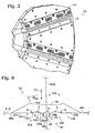
- Figures 1 and 2 show a disc chipper 10.
- On the side of the chipper 10 are a plurality of chipping knives 12 and associated clamps 14 for removably clamping the knives 12 to a cutting head 16 of the chipper 10.
- the cutting head 16 rotates about an axis of rotation "R,” causing each knife 12 to sweep out an annular space.
- the clamps 14 typically include an upper clamping member 14a and a lower clamping, member 14b, the latter often referred to in the art as a "counterknife.”
- the upper and lower clamping members receive respective back and front sides 12a, 12b of the associated knife 12.
- FIG 3 shows a preferred embodiment for clamping the knives 12 in which each clamp 14 includes a base 14c which is bolted to the cutting head 16, and the lower clamping member 14b is disposed between the base and the upper clamping member 14a. Further, preferably, the lower clamping member 14b is adapted for pivotal adjustment about a pivot 22 of the base 14c.
- An adjustment bolt 18 is threadingly received in a through-hole 19 of the upper clamping member 14a, and an end 18a of the bolt is captured in a through-hole 21 of an end 24 of the lower clamping member 14b.
- the lower clamping member 14b is supported by the bolt 18 at the end 24, and by the base 14c at the pivot 22.
- FIG 3 an elongate configuration of the knife 12 can be seen, the knife therefore having an elongate axis "EA."
- Figures 4 and 5 view the knife 12 in a direction parallel to the axis EA.
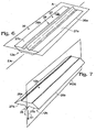
- the knife 12 is shown in perspective in Figures 6 and 7 , and in end view in Figure 8 .
- the knife has two cutting edges 26 lying in a reference plane "A," the edges referenced as 26a and 26b.
- the front side 12b includes two substantially planar knife-edge-joining portions 27, namely 27a and 27b that may also lie in the plane A, but which may be disposed at non-zero angles with respect to the plane A if desired For example, even if the knife-edge-joining portions are originally provided to lie in the plane A, these surfaces may be ground as known in the art to alter the attack angle of the knife 12.
- the deflector ridge 28 reaches a linear edge or line of points "L" of greatest maximum projection of the knife in the direction "D1" indicated by the arrow ( Figure 7 ), from the plane A, the line lying in a plane of reflective symmetry "POS" of the knife.
- the plane of reflective symmetry is perpendicular to the plane A and parallel to the elongate axis EA of the knife. With this symmetry, the knife 12 can be removed from the apparatus when it is in the configuration shown in Figure 5 , turned end-for-end to provide a fresh cutting edge, and reinstalled.
- the deflector ridge 28 has two canted outer surfaces 29, namely 29a and 29b, joining at an apex 29c that is preferably sharp, but which in typical practice is slightly rounded-off, and where the amount of such rounding is not particularly important.
- the outer surfaces 29 may be substantially planar as shown, or may be concave and, preferably, smoothly curving.
- the deflector ridge 28 provides, in the outer surfaces 29, a guiding surface for efficiently guiding cut chips away from the apparatus. This guiding action also protects the lower clamping member 14b from wear as a result of preventing contact with the chips that would otherwise occur. Further, a single deflector ridge may be made larger than the corresponding deflector ridges of a pair without any additional metal being required. This provides for a stronger deflector ridge that is also more capable of providing the aforedescribed functions with no increase in the weight of the knife 12. It also provides for a stronger knife by distributing more metal farther from the neutial axis, as in an I-beam.
- the front side 12b of the knife 12 also includes a pair of indexing features 30, namely 30a and 30b, as will be described.
- the indexing features 30 help, along with the deflector ridge 28, to index the knife to the lower clamping member 14b.
- the indexing features 30 of the knife cooperate with a complementary indexing feature 32 of the lower clamping member, and the features 30 and 32 may be provided with many alternative complementary shapes and dispositions to serve the purpose of providing for knife indexing.
- the indexing features 30 and 32 have specific shapes and dispositions for serving additional purposes as described below.
- each indexing feature 30 is disposed between the corresponding knife-edge-joining portion 27a, 27b and the deflector ridge 28. That is, distal sides "DS1" of the indexing features 30 merge with proximal sides “PS1" of the knife-edge-joining portions 27 at points "Q,” and proximal sides “PS2” of the indexing features 30 merge with distal sides "DS2" of the outer surfaces 29 of the deflector ridge 28 at points "R.”
- the points Q on both sides of the plane of symmetry POS define a plane "B," which in this example is coincident with the plane A but need not be as mentioned above.
- the orientation of the knife shown in Figure 8 is a drawing convention in which the front side of the knife is at the bottom of the Figure, so that the positive direction "D1" is downward.
- the indexing features describe re-entrant contours "C" that intersect the plane B at points Q, and points "S" on these contours are points of minimum projection of the front side 12b of the knife with respect to the positive direction D1.
- This re-entrant disposition of the indexing features 30 provides the advantage of tucking the features up and out of the way of chip flow so that, as the knife-edge-joining portions wear, the indexing features remain in substantially un-worn condition.
- each contour C is preferably shaped as a concave, smoothly varying arc that smoothly merges with the corresponding outer surface 29a, 29b of the deflector ridge 28.
- the complementary feature 32 of the lower clamping member 14b is a convex, smoothly varying arc, as shown in Figure 9 .
- the purpose served by this particular combination of shapes can be seen by reference to Figures 9, 11, and 13 showing, in degrees, the lower clamping member 14b being pivoted up into position against the knife 12, to clamp the knife.
- Figure 9 the lower clamping member 14b is being pivoted upwardly, toward the knife 12, and is about to make first contact with the knife, particularly at the apex 29c of the deflector ridge 28.
- Figure 10 shows the detail circle indicated in Figure 9 .
- a trace "T" is shown of the path of the indexing feature 32 as a result of further upward pivoting of the lower clamping member 14b.
- the trace T foretells an interference that will occur, but has not yet occurred, between the feature 32 and the corresponding indexing feature 30.
- Figures 11 and 12 corresponding to Figures 9 and 10 respectively, show this interference more explicitly, by showing the relative positions of these features in the case that further upward pivoting of the lower clamping member 14b toward the knife 12 has occurred.
- the interference is shown by an overlapping of the indexing features 30 and 32 that, as will be readily appreciated, cannot physically occur.
- Figure 13 shows the final progression of pivoting of the lower clamping member 14b into position against the knife, for clamping the knife in place.
- the knife For the indexing features 30 and 32 to reach the relative positions shown in Figure 13 from those shown in Figure 11 , the knife must first yield the small amount necessary to accommodate the interference shown in Figures 11 and 12 . Such yielding occurs for two reasons. First, there is some compliance in the deflector ridge 28. Second, there is a slight readjustment of the contact that the back side 12a of the knife makes with the upper clamping member 14a as the knife settles into a stable position.
- the upper clamping member 14a includes a projection 34 that is shaped to fit a recess 36 in the back side 12a of the knife 12, to index the knife to the upper clamping member, though the shapes of these features could be reversed, i.e., the projection 34 could be replaced with a recess where the recess 36 is replaced with a corresponding projection.
- Figure 14 shows the detail circle indicated in Figure 13 .
- the projection 34 and the recess 36 have complementary canted sides 34a, 36a that describe respective obtuse angles 0, namely ⁇ 34 , ⁇ 36 , relative to the aforedescribed plane A, where ⁇ 34 > ⁇ 36 .
- This relationship between the angles ⁇ ensures that contact will be made at widely spaced apart points "SP" rather than intermediate points such as the point "IP.” It may also be appreciated that this manner of providing interfering contact between the projection 34 and the recess 36 allows for some movement of the knife (a combination of linear movement parallel to the plane A and rotation) and, such as described above, before the knife settles into its final stable position as shown in Figure 13 .
- the position of the knife 12 relative to the lower clamping member 14b as shown in Figure 13 is stable because the apex 29c of the deflector ridge 28 has traveled "over center” with respect to, or “cammed over” the indexing feature 32 of the lower clamping member.
- the smoothly varying contour C is preferably and most simply a circular arc as indicated in Figure 8 , though a cam-over function could be provided by use of an arc shape that is not circular. It is has been determined that in the system as shown the knife 12 can be felt to "snap" into stable position, providing a reliable tactile indication that the knife has been successfully indexed into proper position.
Landscapes
- Engineering & Computer Science (AREA)
- Life Sciences & Earth Sciences (AREA)
- Manufacturing & Machinery (AREA)
- Mechanical Engineering (AREA)
- Wood Science & Technology (AREA)
- Forests & Forestry (AREA)
- Manufacture Of Wood Veneers (AREA)
- Knives (AREA)
- Debarking, Splitting, And Disintegration Of Timber (AREA)
- Sewing Machines And Sewing (AREA)
- Measurement Of Force In General (AREA)
- Measuring Volume Flow (AREA)
- Measuring Pulse, Heart Rate, Blood Pressure Or Blood Flow (AREA)
- Dovetailed Work, And Nailing Machines And Stapling Machines For Wood (AREA)
Claims (15)
- Un couteau ayant un axe allongé (EA) et deux arêtes de coupe séparées parallèles audit axe allongé, lesdites arêtes de coupe (26a, 26b) définissant un plan de référence (A), le couteau de plus défini par un plan de symétrie réflective (POS) qui est perpendiculaire audit plan de référence et qui contient ledit axe allongé, le couteau ayant une partie avant (12b) et une partie arrière (12a) espacée dudit côté avant, lesdites parties avant et arrière se terminant en lesdites arêtes de coupe, lesdites parties avant et arrière définissant une direction positive perpendiculaire audit plan de référence, passant de ladite partie arrière (12a) vers la partie avant (12b) caractérisé par un rebord déflecteur (28) faisant saillie de ladite partie avant et atteignant un premier point (L) de projection maximum la plus grande du couteau dans ladite direction positive, ledit point se trouvant dans ledit plan de symétrie réflective, et deux caractéristiques de positionnement (30a, 30b) de ladite partie avant identiques en substance disposées sur chaque partie dudit rebord déflecteur et correspondant respectivement auxdites deux arêtes de coupe (26a, 26b), chacune desdites caractéristiques de positionnement ayant un second point de projection minimum (S) de ladite partie avant (12b) dans ladite direction positive et un troisième point (Q) se projetant plus loin dans ladite direction positive que ledit second point (S) moins que ledit premier point (L), lesdits premier, second et troisième points tous se trouvant dans un plan qui est perpendiculaire aux deux dits plans de référence (A) et plan de symétrie réflective (POS), ledit troisième point (Q) étant disposé plus loin dudit plan de symétrie réflective que ledit second point (S).
- Le couteau de la revendication 1 où ladite partie arrière inclut au moins un parmi (a) une gorge et (b) une saillie, pour positionner le couteau, et où ledit un parmi (a) et (b) inclut des parties chanfreinées définissant un angle obtu θ relativement audit premier plan de référence.
- Le couteau de la revendication 1, où les caractéristiques de positionnement définissent des arcs en substance circulaires.
- Le couteau de la revendication 3, où la partie arrière inclut au moins un parmi (a) une gorge et (b) une saillie, pour positionner le couteau, et où ledit un parmi (a) et (b) inclut des parties chanfreinées définissant un angle obtu ϑ relativement audit premier plan de référence.
- Le couteau de la revendication 4, ladite partie avant incluant de plus deux portions de liaison d'arêtes de couteau planaires, chaque portion de liaison d'arêtes de couteau se terminant dans une desdites arêtes de coupe et le troisième point de la caractéristique de positionnement correspondante.
- Le couteau de la revendication 5, où lesdites portions de liaison d'arêtes de couteau sont en substance coplanaires.
- Le couteau de la revendication 2, ladite partie avant incluant de plus deux portions de liaison d'arêtes de couteau en substance planaires, chaque portion de liaison d'arête de couteau se terminant en un desdites arêtes de coupe et le troisième point de la caractéristique de positionnement correspondante.
- Le couteau de la revendication 7, où lesdites portions de liaison d'arêtes de couteau sont en substance coplanaires.
- Le couteau de la revendication 1, ladite partie avant incluant de plus deux portions de liaison d'arêtes de couteau en substance planaires, chaque portion de liaison d'arête de couteau se terminant en un desdites arêtes de coupe et le troisième point de la caractéristique de positionnement correspondante.
- Le couteau de la revendication 9, où lesdites portions de liaison d'arêtes de couteau sont en substance coplanaires.
- Un assemblage de couteau comprenant :un élément de serrage supérieur (14a) adapté pour recevoir ladite partie arrière du couteau ;un élément de serrage inférieur (146) adapté pour recevoir ladite partie avant du couteau, lesdits éléments de serrage supérieur et inférieur pour y serrer le couteau entre : et un couteau selon la revendication 1.
- L'ensemble couteau de la revendication 11, où ladite partie arrière et ledit élément de serrage supérieur incluent au moins un parmi (a) une gorge et une saillie et (b) une saillie et une gorge, respectivement, pour positionner ledit couteau audit élément de serrage supérieur, où ledit un parmi (a) et (b) inclut des côtés chanfreinés définissant des angles obtus θ1 et θ2 relativement audit premier plan de référence et correspondant respectivement à ladite saillie et ladite gorge, où θ1 > θ2.
- L'ensemble couteau selon une des revendications 11 ou 12, ladite partie avant incluant deux portions de liaison d'arêtes de couteau en substance planaires, chaque portion de liaison d'arêtes de couteau se terminant en un parmi lesdites arêtes de coupe et le troisième point de la caractéristique de positionnement correspondante.
- L'ensemble couteau de la revendication 11, où lesdites caractéristiques de positionnement définissent des arcs en substance circulaires.
- L'ensemble couteau de la revendication 14, où ladite partie arrière et ledit élément de serrage supérieur inclut au moins un parmi (a) une gorge et une saillie et (b) une saillie et une gorge, respectivement, pour positionner ledit couteau audit élément de serrage supérieur, où ledit un parmi (a) et (b) inclut des côtés chanfreinés définissant des angles obtus θ1 et θ2 relativement audit premier plan de référence et correspondant respectivement à ladite saillie et ladite gorge, où θ1 > θ2.
Applications Claiming Priority (2)
| Application Number | Priority Date | Filing Date | Title |
|---|---|---|---|
| US11/347,472 US7140408B1 (en) | 2006-02-03 | 2006-02-03 | Knife assembly and chipping knife therefor |
| PCT/US2007/000312 WO2007092110A1 (fr) | 2006-02-03 | 2007-01-08 | ensemble coupant et couteau de dechiquetage adapte |
Publications (2)
| Publication Number | Publication Date |
|---|---|
| EP1984155A1 EP1984155A1 (fr) | 2008-10-29 |
| EP1984155B1 true EP1984155B1 (fr) | 2009-08-26 |
Family
ID=37449811
Family Applications (1)
| Application Number | Title | Priority Date | Filing Date |
|---|---|---|---|
| EP07716378A Active EP1984155B1 (fr) | 2006-02-03 | 2007-01-08 | Ensemble coupant et couteau de dechiquetage adapte |
Country Status (9)
| Country | Link |
|---|---|
| US (2) | US7140408B1 (fr) |
| EP (1) | EP1984155B1 (fr) |
| AT (1) | ATE440712T1 (fr) |
| AU (1) | AU2007212766B2 (fr) |
| BR (1) | BRPI0706909A2 (fr) |
| CA (1) | CA2636372C (fr) |
| DE (1) | DE602007002164D1 (fr) |
| ES (1) | ES2332293T3 (fr) |
| WO (1) | WO2007092110A1 (fr) |
Families Citing this family (17)
| Publication number | Priority date | Publication date | Assignee | Title |
|---|---|---|---|---|
| CA2686670C (fr) * | 2002-01-17 | 2012-09-25 | Iggesund Tools Ab | Couteau a travailler le bois polyvalent et dispositif de serrage |
| US7140408B1 (en) * | 2006-02-03 | 2006-11-28 | Key Knife, Inc. | Knife assembly and chipping knife therefor |
| US7614831B2 (en) * | 2006-03-13 | 2009-11-10 | Panasonic Corporation | Machining tools having concave cutting surfaces for precision machining and methods of manufacturing such |
| US20070251601A1 (en) * | 2006-05-01 | 2007-11-01 | Stager Bradley R | Drum chipper and method providing for air cooling |
| US7677282B2 (en) * | 2006-11-22 | 2010-03-16 | Key Knife, Inc. | Knife assembly and chipping knife therefor |
| US8033308B2 (en) * | 2007-01-08 | 2011-10-11 | Key Knife, Inc. | Double-sided wear insert for a chipper |
| DE102007022242A1 (de) * | 2007-05-09 | 2008-11-20 | Leitz Gmbh & Co. Kg | Schneidwerkzeug mit einem Tragkörper |
| SE531637C2 (sv) * | 2007-10-24 | 2009-06-16 | Iggesund Tools Ab | Huggkniv, huggknivsenhet samt ett förfarande för montering av en huggkniv |
| US20090200411A1 (en) * | 2008-02-07 | 2009-08-13 | Stager Bradley R | Chipping knife and assembly |
| JP4803306B1 (ja) * | 2010-04-07 | 2011-10-26 | ソニー株式会社 | 電池パックおよび電池パックの製造方法 |
| USD705274S1 (en) * | 2011-08-30 | 2014-05-20 | Andritz Iggesund Tools Ab | Knife clamp assembly |
| CN102862203A (zh) * | 2012-09-03 | 2013-01-09 | 江苏大唐机械有限公司 | 环式刨片机防护板式叶轮 |
| CH709488A1 (de) | 2014-04-14 | 2015-10-15 | Oertli Werkzeuge Ag | Werkzeugkopf und Verfahren zum Einsetzen und Spannen einer Schneidplatte, sowie Schneidplatte. |
| USD772316S1 (en) * | 2015-04-01 | 2016-11-22 | Zenith Cutter, Inc. | Knife assembly |
| USD772317S1 (en) | 2015-04-01 | 2016-11-22 | Zenith Cutter, Inc. | Knife insert |
| SE543956C2 (en) * | 2019-01-14 | 2021-10-05 | Andritz Ab | Wood chipper knife comprising a recess in the wood attacking portion |
| CA216417S (en) | 2020-07-13 | 2022-10-18 | Andritz Ab | Wood chipper knife |
Family Cites Families (15)
| Publication number | Priority date | Publication date | Assignee | Title |
|---|---|---|---|---|
| SE393763B (sv) | 1973-10-25 | 1977-05-23 | Iggesunds Bruk Ab | Knivanordning for fliskuggmaskin |
| SE405081B (sv) | 1974-02-07 | 1978-11-20 | Sandvik Ab | Kniv for tyngre bearbetning |
| US4669516A (en) * | 1985-11-18 | 1987-06-02 | Duratech, Inc. | V-shaped chipper knife |
| SE459646B (sv) * | 1986-08-27 | 1989-07-24 | Jonsson Karl Erik Arnold | Treeggat verktyg foer en traebearbetningsmaskin |
| DE9108553U1 (de) * | 1991-07-12 | 1991-09-12 | Michael Weinig AG, 6972 Tauberbischofsheim | Messerkopf, insbesondere Hobelkopf |
| SE9102796L (sv) | 1991-09-25 | 1993-03-26 | Iggesund Tools Ab | Anordning vid fraeshuvuden |
| AT398401B (de) * | 1992-08-26 | 1994-12-27 | Boehler Ybbstalwerke | Wendemesser, insbesondere wendehobelmesser |
| SE504431C2 (sv) | 1994-06-29 | 1997-02-10 | Iggesund Tools Ab | Knivanordning |
| FI96288C (fi) * | 1995-04-20 | 1996-06-10 | Kone Wood Oy | Laite terän kiinnittämiseksi hakun pyöritettävään kiekkoon |
| US5819826A (en) | 1997-10-23 | 1998-10-13 | Key Knife, Inc. | Chip cutting knife with spaced deflector ridges |
| US5979522A (en) | 1998-11-18 | 1999-11-09 | Key Knife, Inc. | Knife holder for a chipper disc |
| US6968879B2 (en) * | 2001-07-30 | 2005-11-29 | Key Knife, Inc. | Knife and apparatus for clamping a knife |
| CA2686670C (fr) | 2002-01-17 | 2012-09-25 | Iggesund Tools Ab | Couteau a travailler le bois polyvalent et dispositif de serrage |
| US7069969B2 (en) * | 2003-09-25 | 2006-07-04 | Key Knife, Inc. | Wood cutting knife assembly providing improved knife stability |
| US7140408B1 (en) * | 2006-02-03 | 2006-11-28 | Key Knife, Inc. | Knife assembly and chipping knife therefor |
-
2006
- 2006-02-03 US US11/347,472 patent/US7140408B1/en not_active Expired - Lifetime
-
2007
- 2007-01-08 ES ES07716378T patent/ES2332293T3/es active Active
- 2007-01-08 EP EP07716378A patent/EP1984155B1/fr active Active
- 2007-01-08 BR BRPI0706909-0A patent/BRPI0706909A2/pt active IP Right Grant
- 2007-01-08 WO PCT/US2007/000312 patent/WO2007092110A1/fr not_active Ceased
- 2007-01-08 AU AU2007212766A patent/AU2007212766B2/en active Active
- 2007-01-08 DE DE602007002164T patent/DE602007002164D1/de active Active
- 2007-01-08 US US12/223,423 patent/US20090025829A1/en not_active Abandoned
- 2007-01-08 AT AT07716378T patent/ATE440712T1/de not_active IP Right Cessation
- 2007-01-08 CA CA2636372A patent/CA2636372C/fr active Active
Also Published As
| Publication number | Publication date |
|---|---|
| AU2007212766B2 (en) | 2010-08-12 |
| US7140408B1 (en) | 2006-11-28 |
| AU2007212766A1 (en) | 2007-08-16 |
| CA2636372A1 (fr) | 2007-08-16 |
| DE602007002164D1 (de) | 2009-10-08 |
| EP1984155A1 (fr) | 2008-10-29 |
| ATE440712T1 (de) | 2009-09-15 |
| ES2332293T3 (es) | 2010-02-01 |
| BRPI0706909A2 (pt) | 2011-04-12 |
| CA2636372C (fr) | 2010-09-21 |
| WO2007092110A1 (fr) | 2007-08-16 |
| US20090025829A1 (en) | 2009-01-29 |
Similar Documents
| Publication | Publication Date | Title |
|---|---|---|
| EP1984155B1 (fr) | Ensemble coupant et couteau de dechiquetage adapte | |
| US5819826A (en) | Chip cutting knife with spaced deflector ridges | |
| US8033308B2 (en) | Double-sided wear insert for a chipper | |
| WO2008063201A1 (fr) | Ensemble coupant et couteau de déchiquetage correspondant | |
| US6591878B2 (en) | Method and apparatus for clamping a knife | |
| US20090200411A1 (en) | Chipping knife and assembly | |
| US7069969B2 (en) | Wood cutting knife assembly providing improved knife stability | |
| US20210138683A1 (en) | Wood Chipping Knife for use with Clamping Assembly | |
| US5409047A (en) | Chipper knife | |
| CA3106561C (fr) | Lame de dechiqueteuse a bois | |
| US8082958B2 (en) | Knives and knife assemblies | |
| US20060208120A1 (en) | Chipper knife | |
| US20070102062A1 (en) | Drum flaker and knife therefor | |
| EP1513659B1 (fr) | Lame de dechiqueteuse | |
| CA2489715C (fr) | Couteau a bois a stabilite amelioree | |
| US20070160430A1 (en) | Milling cutter | |
| CA2135146C (fr) | Couteau de dechiquetage |
Legal Events
| Date | Code | Title | Description |
|---|---|---|---|
| PUAI | Public reference made under article 153(3) epc to a published international application that has entered the european phase |
Free format text: ORIGINAL CODE: 0009012 |
|
| 17P | Request for examination filed |
Effective date: 20080903 |
|
| AK | Designated contracting states |
Kind code of ref document: A1 Designated state(s): AT BE BG CH CY CZ DE DK EE ES FI FR GB GR HU IE IS IT LI LT LU LV MC NL PL PT RO SE SI SK TR |
|
| RIN1 | Information on inventor provided before grant (corrected) |
Inventor name: LIAO, JIANMIN Inventor name: HINCHLIFF, THOMAS, CHARLES |
|
| GRAP | Despatch of communication of intention to grant a patent |
Free format text: ORIGINAL CODE: EPIDOSNIGR1 |
|
| GRAS | Grant fee paid |
Free format text: ORIGINAL CODE: EPIDOSNIGR3 |
|
| GRAA | (expected) grant |
Free format text: ORIGINAL CODE: 0009210 |
|
| AK | Designated contracting states |
Kind code of ref document: B1 Designated state(s): AT BE BG CH CY CZ DE DK EE ES FI FR GB GR HU IE IS IT LI LT LU LV MC NL PL PT RO SE SI SK TR |
|
| REG | Reference to a national code |
Ref country code: GB Ref legal event code: FG4D |
|
| REG | Reference to a national code |
Ref country code: CH Ref legal event code: EP |
|
| REG | Reference to a national code |
Ref country code: IE Ref legal event code: FG4D |
|
| REF | Corresponds to: |
Ref document number: 602007002164 Country of ref document: DE Date of ref document: 20091008 Kind code of ref document: P |
|
| LTIE | Lt: invalidation of european patent or patent extension |
Effective date: 20090826 |
|
| PG25 | Lapsed in a contracting state [announced via postgrant information from national office to epo] |
Ref country code: IS Free format text: LAPSE BECAUSE OF FAILURE TO SUBMIT A TRANSLATION OF THE DESCRIPTION OR TO PAY THE FEE WITHIN THE PRESCRIBED TIME-LIMIT Effective date: 20091226 Ref country code: FI Free format text: LAPSE BECAUSE OF FAILURE TO SUBMIT A TRANSLATION OF THE DESCRIPTION OR TO PAY THE FEE WITHIN THE PRESCRIBED TIME-LIMIT Effective date: 20090826 Ref country code: LT Free format text: LAPSE BECAUSE OF FAILURE TO SUBMIT A TRANSLATION OF THE DESCRIPTION OR TO PAY THE FEE WITHIN THE PRESCRIBED TIME-LIMIT Effective date: 20090826 Ref country code: AT Free format text: LAPSE BECAUSE OF FAILURE TO SUBMIT A TRANSLATION OF THE DESCRIPTION OR TO PAY THE FEE WITHIN THE PRESCRIBED TIME-LIMIT Effective date: 20090826 Ref country code: SE Free format text: LAPSE BECAUSE OF FAILURE TO SUBMIT A TRANSLATION OF THE DESCRIPTION OR TO PAY THE FEE WITHIN THE PRESCRIBED TIME-LIMIT Effective date: 20090826 |
|
| NLV1 | Nl: lapsed or annulled due to failure to fulfill the requirements of art. 29p and 29m of the patents act | ||
| REG | Reference to a national code |
Ref country code: ES Ref legal event code: FG2A Ref document number: 2332293 Country of ref document: ES Kind code of ref document: T3 |
|
| PG25 | Lapsed in a contracting state [announced via postgrant information from national office to epo] |
Ref country code: PL Free format text: LAPSE BECAUSE OF FAILURE TO SUBMIT A TRANSLATION OF THE DESCRIPTION OR TO PAY THE FEE WITHIN THE PRESCRIBED TIME-LIMIT Effective date: 20090826 Ref country code: NL Free format text: LAPSE BECAUSE OF FAILURE TO SUBMIT A TRANSLATION OF THE DESCRIPTION OR TO PAY THE FEE WITHIN THE PRESCRIBED TIME-LIMIT Effective date: 20090826 Ref country code: SI Free format text: LAPSE BECAUSE OF FAILURE TO SUBMIT A TRANSLATION OF THE DESCRIPTION OR TO PAY THE FEE WITHIN THE PRESCRIBED TIME-LIMIT Effective date: 20090826 Ref country code: LV Free format text: LAPSE BECAUSE OF FAILURE TO SUBMIT A TRANSLATION OF THE DESCRIPTION OR TO PAY THE FEE WITHIN THE PRESCRIBED TIME-LIMIT Effective date: 20090826 |
|
| PG25 | Lapsed in a contracting state [announced via postgrant information from national office to epo] |
Ref country code: CY Free format text: LAPSE BECAUSE OF FAILURE TO SUBMIT A TRANSLATION OF THE DESCRIPTION OR TO PAY THE FEE WITHIN THE PRESCRIBED TIME-LIMIT Effective date: 20090826 Ref country code: BG Free format text: LAPSE BECAUSE OF FAILURE TO SUBMIT A TRANSLATION OF THE DESCRIPTION OR TO PAY THE FEE WITHIN THE PRESCRIBED TIME-LIMIT Effective date: 20091126 Ref country code: PT Free format text: LAPSE BECAUSE OF FAILURE TO SUBMIT A TRANSLATION OF THE DESCRIPTION OR TO PAY THE FEE WITHIN THE PRESCRIBED TIME-LIMIT Effective date: 20091228 |
|
| PG25 | Lapsed in a contracting state [announced via postgrant information from national office to epo] |
Ref country code: DK Free format text: LAPSE BECAUSE OF FAILURE TO SUBMIT A TRANSLATION OF THE DESCRIPTION OR TO PAY THE FEE WITHIN THE PRESCRIBED TIME-LIMIT Effective date: 20090826 Ref country code: CZ Free format text: LAPSE BECAUSE OF FAILURE TO SUBMIT A TRANSLATION OF THE DESCRIPTION OR TO PAY THE FEE WITHIN THE PRESCRIBED TIME-LIMIT Effective date: 20090826 Ref country code: RO Free format text: LAPSE BECAUSE OF FAILURE TO SUBMIT A TRANSLATION OF THE DESCRIPTION OR TO PAY THE FEE WITHIN THE PRESCRIBED TIME-LIMIT Effective date: 20090826 Ref country code: EE Free format text: LAPSE BECAUSE OF FAILURE TO SUBMIT A TRANSLATION OF THE DESCRIPTION OR TO PAY THE FEE WITHIN THE PRESCRIBED TIME-LIMIT Effective date: 20090826 |
|
| PG25 | Lapsed in a contracting state [announced via postgrant information from national office to epo] |
Ref country code: SK Free format text: LAPSE BECAUSE OF FAILURE TO SUBMIT A TRANSLATION OF THE DESCRIPTION OR TO PAY THE FEE WITHIN THE PRESCRIBED TIME-LIMIT Effective date: 20090826 |
|
| PG25 | Lapsed in a contracting state [announced via postgrant information from national office to epo] |
Ref country code: BE Free format text: LAPSE BECAUSE OF FAILURE TO SUBMIT A TRANSLATION OF THE DESCRIPTION OR TO PAY THE FEE WITHIN THE PRESCRIBED TIME-LIMIT Effective date: 20090826 |
|
| PLBE | No opposition filed within time limit |
Free format text: ORIGINAL CODE: 0009261 |
|
| STAA | Information on the status of an ep patent application or granted ep patent |
Free format text: STATUS: NO OPPOSITION FILED WITHIN TIME LIMIT |
|
| 26N | No opposition filed |
Effective date: 20100527 |
|
| PG25 | Lapsed in a contracting state [announced via postgrant information from national office to epo] |
Ref country code: MC Free format text: LAPSE BECAUSE OF NON-PAYMENT OF DUE FEES Effective date: 20100131 |
|
| PG25 | Lapsed in a contracting state [announced via postgrant information from national office to epo] |
Ref country code: GR Free format text: LAPSE BECAUSE OF FAILURE TO SUBMIT A TRANSLATION OF THE DESCRIPTION OR TO PAY THE FEE WITHIN THE PRESCRIBED TIME-LIMIT Effective date: 20091127 |
|
| PG25 | Lapsed in a contracting state [announced via postgrant information from national office to epo] |
Ref country code: IE Free format text: LAPSE BECAUSE OF NON-PAYMENT OF DUE FEES Effective date: 20100108 |
|
| PG25 | Lapsed in a contracting state [announced via postgrant information from national office to epo] |
Ref country code: IT Free format text: LAPSE BECAUSE OF FAILURE TO SUBMIT A TRANSLATION OF THE DESCRIPTION OR TO PAY THE FEE WITHIN THE PRESCRIBED TIME-LIMIT Effective date: 20090826 |
|
| REG | Reference to a national code |
Ref country code: CH Ref legal event code: PL |
|
| GBPC | Gb: european patent ceased through non-payment of renewal fee |
Effective date: 20110108 |
|
| PG25 | Lapsed in a contracting state [announced via postgrant information from national office to epo] |
Ref country code: LI Free format text: LAPSE BECAUSE OF NON-PAYMENT OF DUE FEES Effective date: 20110131 Ref country code: CH Free format text: LAPSE BECAUSE OF NON-PAYMENT OF DUE FEES Effective date: 20110131 |
|
| PG25 | Lapsed in a contracting state [announced via postgrant information from national office to epo] |
Ref country code: GB Free format text: LAPSE BECAUSE OF NON-PAYMENT OF DUE FEES Effective date: 20110108 |
|
| PG25 | Lapsed in a contracting state [announced via postgrant information from national office to epo] |
Ref country code: LU Free format text: LAPSE BECAUSE OF NON-PAYMENT OF DUE FEES Effective date: 20100108 Ref country code: HU Free format text: LAPSE BECAUSE OF FAILURE TO SUBMIT A TRANSLATION OF THE DESCRIPTION OR TO PAY THE FEE WITHIN THE PRESCRIBED TIME-LIMIT Effective date: 20100227 |
|
| PG25 | Lapsed in a contracting state [announced via postgrant information from national office to epo] |
Ref country code: TR Free format text: LAPSE BECAUSE OF FAILURE TO SUBMIT A TRANSLATION OF THE DESCRIPTION OR TO PAY THE FEE WITHIN THE PRESCRIBED TIME-LIMIT Effective date: 20090826 |
|
| REG | Reference to a national code |
Ref country code: FR Ref legal event code: PLFP Year of fee payment: 10 |
|
| REG | Reference to a national code |
Ref country code: FR Ref legal event code: PLFP Year of fee payment: 11 |
|
| REG | Reference to a national code |
Ref country code: FR Ref legal event code: PLFP Year of fee payment: 12 |
|
| PGFP | Annual fee paid to national office [announced via postgrant information from national office to epo] |
Ref country code: ES Payment date: 20260220 Year of fee payment: 20 |
|
| PGFP | Annual fee paid to national office [announced via postgrant information from national office to epo] |
Ref country code: DE Payment date: 20260115 Year of fee payment: 20 |
|
| PGFP | Annual fee paid to national office [announced via postgrant information from national office to epo] |
Ref country code: FR Payment date: 20260126 Year of fee payment: 20 |