EP1984549B1 - Machine permettant de fabriquer des tissus maillés en matière fibreuse, en particulier métier à tricoter circulaire - Google Patents
Machine permettant de fabriquer des tissus maillés en matière fibreuse, en particulier métier à tricoter circulaire Download PDFInfo
- Publication number
- EP1984549B1 EP1984549B1 EP07711190A EP07711190A EP1984549B1 EP 1984549 B1 EP1984549 B1 EP 1984549B1 EP 07711190 A EP07711190 A EP 07711190A EP 07711190 A EP07711190 A EP 07711190A EP 1984549 B1 EP1984549 B1 EP 1984549B1
- Authority
- EP
- European Patent Office
- Prior art keywords
- drawing equipment
- drafting
- rollers
- machine according
- pair
- Prior art date
- Legal status (The legal status is an assumption and is not a legal conclusion. Google has not performed a legal analysis and makes no representation as to the accuracy of the status listed.)
- Not-in-force
Links
- 238000009940 knitting Methods 0.000 title claims abstract description 70
- 239000002657 fibrous material Substances 0.000 title claims abstract description 39
- 239000004744 fabric Substances 0.000 title claims abstract description 5
- 238000003780 insertion Methods 0.000 claims description 53
- 230000037431 insertion Effects 0.000 claims description 53
- 230000008878 coupling Effects 0.000 claims description 16
- 238000010168 coupling process Methods 0.000 claims description 16
- 238000005859 coupling reaction Methods 0.000 claims description 16
- 238000000429 assembly Methods 0.000 description 21
- 230000000712 assembly Effects 0.000 description 21
- 238000009987 spinning Methods 0.000 description 13
- 239000000835 fiber Substances 0.000 description 9
- 210000000056 organ Anatomy 0.000 description 9
- 230000015572 biosynthetic process Effects 0.000 description 8
- 230000008901 benefit Effects 0.000 description 6
- 238000007664 blowing Methods 0.000 description 5
- 238000010276 construction Methods 0.000 description 4
- 238000013461 design Methods 0.000 description 3
- 230000008439 repair process Effects 0.000 description 3
- 230000000694 effects Effects 0.000 description 2
- 238000012423 maintenance Methods 0.000 description 2
- 238000004519 manufacturing process Methods 0.000 description 2
- 238000012856 packing Methods 0.000 description 2
- 230000002776 aggregation Effects 0.000 description 1
- 238000004220 aggregation Methods 0.000 description 1
- 230000005540 biological transmission Effects 0.000 description 1
- 230000008859 change Effects 0.000 description 1
- 238000007796 conventional method Methods 0.000 description 1
- 230000003247 decreasing effect Effects 0.000 description 1
- 230000001419 dependent effect Effects 0.000 description 1
- 238000005265 energy consumption Methods 0.000 description 1
- 238000005516 engineering process Methods 0.000 description 1
- 238000002474 experimental method Methods 0.000 description 1
- 230000002349 favourable effect Effects 0.000 description 1
- 230000014509 gene expression Effects 0.000 description 1
- 230000012447 hatching Effects 0.000 description 1
- 230000002093 peripheral effect Effects 0.000 description 1
- 238000012545 processing Methods 0.000 description 1
- 230000001681 protective effect Effects 0.000 description 1
- 230000009467 reduction Effects 0.000 description 1
- 238000000926 separation method Methods 0.000 description 1
- 239000002689 soil Substances 0.000 description 1
- 238000011144 upstream manufacturing Methods 0.000 description 1
Images





Classifications
-
- D—TEXTILES; PAPER
- D01—NATURAL OR MAN-MADE THREADS OR FIBRES; SPINNING
- D01H—SPINNING OR TWISTING
- D01H5/00—Drafting machines or arrangements ; Threading of roving into drafting machine
- D01H5/18—Drafting machines or arrangements without fallers or like pinned bars
- D01H5/28—Drafting machines or arrangements without fallers or like pinned bars in which fibres are controlled by inserting twist during drafting
-
- D—TEXTILES; PAPER
- D01—NATURAL OR MAN-MADE THREADS OR FIBRES; SPINNING
- D01H—SPINNING OR TWISTING
- D01H1/00—Spinning or twisting machines in which the product is wound-up continuously
-
- D—TEXTILES; PAPER
- D04—BRAIDING; LACE-MAKING; KNITTING; TRIMMINGS; NON-WOVEN FABRICS
- D04B—KNITTING
- D04B15/00—Details of, or auxiliary devices incorporated in, weft knitting machines, restricted to machines of this kind
- D04B15/94—Driving-gear not otherwise provided for
-
- D—TEXTILES; PAPER
- D04—BRAIDING; LACE-MAKING; KNITTING; TRIMMINGS; NON-WOVEN FABRICS
- D04B—KNITTING
- D04B35/00—Details of, or auxiliary devices incorporated in, knitting machines, not otherwise provided for
- D04B35/22—Devices for preparatory treatment of threads
-
- D—TEXTILES; PAPER
- D04—BRAIDING; LACE-MAKING; KNITTING; TRIMMINGS; NON-WOVEN FABRICS
- D04B—KNITTING
- D04B9/00—Circular knitting machines with independently-movable needles
- D04B9/14—Circular knitting machines with independently-movable needles with provision for incorporating loose fibres, e.g. in high-pile fabrics
Definitions
- the invention relates to a machine of the type specified in the preamble of claim 1 for the production of a knitted fabric made of fiber material, in particular a circular knitting machine, as they are known from DE 2451900 is well known.
- Machines of this type are characterized by the fact that, instead of conventional yarns, predominantly or exclusively threads are used which consist of largely untwisted staple fibers arranged parallel to one another.
- Such threads are produced in draw frames, which are immediately upstream of the stitch forming points of the machine from them supplied Lunten or tapes and converted to ensure trouble-free transport from the drafting to the Ma-schen Struktursstellen by means of spin organs in temporary yarns whose rotations until shortly before the inlet into the stitch formation sites are dismantled again (false-twist principle).
- the actually processed into knit fabric threads therefore consist essentially of untwisted, parallel fibers, which is why the finished knitwear is characterized by an extreme softness. If necessary, additional auxiliary yarns consisting of classical yarns can be incorporated, but this is basically not necessary.
- a known, designed as a circular knitting machine of the type described ( PCT WO 2004/079068 A2 ) has a drafting system for each stitch formation point. Since the drafting systems can not be made arbitrarily small, it results in a significant space and handling problem. It is therefore provided, for example, to arrange the drafting systems with comparatively large distances from the circular knitting machine and to surround them with an elevated platform from which the drafting systems are accessible. This makes it possible to arrange a large number of drafting devices on the circumference of the circular knitting machine, but this is achieved with the disadvantage that the operator working on the circular knitting machine, if an error occurs in one of the drafting units, leave the usual working space in front of the machine, enter the work platform, from there from the error and then return to the usual work space must.
- the technical problem of the invention is to design the machine of the type described so that the drafting arranged even at high system densities close to the machine and yet easy to use, maintained and possibly repaired.
- the invention has the advantage that the drafting systems can be operated from below and / or from the side in comparison to the hitherto exclusively customary manner.
- known pressure arms in which the so-called. Upper rollers are mounted, are arranged so that they can be pivoted downwards or to the side instead of upwards.
- Another preferred possibility is to mount at least selected functional parts, in particular drafting device elements such as rollers or straps, on a component which can be pulled downwards or sideways out of the associated drafting arrangement in the manner of a push-in part. This makes it possible to bring the drafting systems close to the stitch formation or knitting points, although they are preferably arranged above the knitting points, but nevertheless remain in the grip area of the operator working on the machine. The operator can therefore, without having to leave the usual work space to perform all necessary work on the drafting systems by folding the functional parts down or to the side or pulls out.
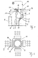
- Fig. 1 and 2 schematically show a circular knitting machine 1 with a rotatable needle cylinder 2, are mounted in the knitting needles 3 slidably.
- a working space 4 is schematically indicated, in which an operator 5 stops during normal work on the circular knitting machine 1.
- the height of the circular knitting machine 1 is dimensioned in a conventional manner so that a plurality of stitch forming or knitting 6, which are formed by lock parts, not shown, and of which in Fig. 1 only one is shown in the grip area of the operator 5 is located.
- the term "handle area” is understood to mean that area which preferably has an ergonomically favorable and / or z. B. by work instructions, standards or otherwise prescribed distance above a soil 7 od.
- the circular knitting machine 1 of interest in the context of the present invention is designed as a so-called spinning knitting machine.
- Each stitch formation or knitting point 6 is assigned to a drafting 8, which is fed to a tipped from a pot 9 sliver 10.
- This sliver 10 is refined in the drafting device 8 in a conventional manner to a thread 11 and preferably presented by means of a yarn guide 12 the knitting needles 3 for stitch formation.
- an auxiliary thread is further indicated, which can also be supplied to the yarn guide 12.
- drafting group 8a in the exemplary embodiment, which provide the threads 11 for six adjacent, here by the yarn guide 12 marked knitting points.
- z. B six drafting 8 arranged coaxially horizontal rollers side by side, so that the Fig. 2 apparent, bar-shaped arrangement with z. B. four drafting groups 8a results, which are arranged on the circumference of the needle cylinder 2 and provide threads 11 for a total of 24 knitting points.
- the drafting units 8 are arranged so that they are like the knitting points 6 in the grip region of the operating on the circular knitting machine 1 operator 5.
- the drafting 8 z. B. attached to a support ring 15 which is supported by means of columns 16 on a base or lock plate 17 of the circular knitting machine 1.
- the arrangement is also made such that the nip lines formed by three or more pairs of functional parts (eg drafting rollers 18 or the like) do not lie in horizontal planes but in a corresponding manner Fig. 1 lie in oblique planes, wherein the respective cans 9 facing input roller pairs are higher than the circular knitting machine 1 facing output roller pairs above the ground 7.
- the embodiment according to Fig. 1 and 2 is characterized in that the axes of the drafting rollers 18 are all arranged horizontally in the use state.
- the drafting 8 can be at least partially opened by their essential functional parts according to the invention are mounted at least partially pivotally downwards in the drafting units 8.
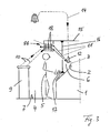
- the embodiment according to Fig. 3 and 4 differs from the embodiment according to Fig. 1 and 2 mainly in that the drafting 8 here in one opposite Fig. 1 rotated by 90 ° position mounted on the circular knitting machine 1 and are arranged vertically instead of horizontally in use. Same parts are therefore in Fig. 3 and 4 with the same reference numerals as in Fig. 1 and 2 Mistake. Pairs of associated drafting 8 come accordingly Fig. 4 to lie next to each other. Fig. 4 also shows that here the pressure arms 19, which carry the so-called top rollers (18a) are pivotable about pivot axes 20, compared to Fig. 1 are also rotated by 90 ° and are vertical.
- Fig. 4a and 4b 4 shows a conventional pressure arm 19 and its actuating and locking elements 19a, 19b in the closed state (FIG. Fig. 4a ) and in the open state ( Fig. 4b ) demonstrate.
- the pressure arms 19 have a sufficiently large swivel range and when opening a drafting system 8 does not encounter immediately against an adjacent drafting, according to the embodiment according to Fig. 3 and 4 as only in Fig. 4 is indicated, be provided that the drafting 8 leaving threads 11 are fed by means of spinning devices 21 to the associated knitting points.
- These spinning devices 21 contain, as is known from the document mentioned, z.
- the spinning devices 21 serve the purpose of initially converting the emerging from the drafting 8 threads 11 into temporary yarns with real rotations, the 23 between the ends of the spinning tubes and the knitting points 6 associated yarn guides 12 ( Fig. 3 ) are resolved again due to the so-called false-wire effect.
- the distance of the drafting units 8 from the central axis of the needle cylinder 2 can be comparatively large and largely arbitrarily selected.
- the distance between two adjacent drafting units 8 that results in the circumferential direction can also be set to a preselected value enabling pivoting of the pressure arms 19.
- Corresponding spinning devices 21 can in the embodiment according to Fig. 1 and 2 be provided.
- the embodiment has Fig. 3 and 4 towards the Fig. 1 and 2 the advantage that the drafting rollers 18, since they are perpendicular, can be driven in a simple manner by extending in the circumferential direction of the needle cylinder 2, circularly mounted and arranged above the drafting drive belt.
- the waves of each so-called lower roller of the three roller pairs shown on their upper sides z. B. each provided with a toothed belt pulley.
- a corresponding drive could for the lower rollers of the embodiment according to Fig. 1 and 2 be provided.
- the drive torques transmitted by means of the toothed belts would have to be converted by means of bevel gears or the like into torques for the lower rollers arranged horizontally here.
- Fig. 3 shows that here two or more drafting with their rollers 18 can be arranged coaxially one above the other. This makes it possible to halve or even more to reduce the space required in the circumferential direction for the drafting 8, since in this case, two or more threads from each drafting segment segment can be guided to adjacent knitting points, as in Fig. 3 is indicated by two threads 11. As a result, the packing density stretched goods can be doubled or tripled.
- the invention has hitherto been described with reference to the drafting arrangements 8, which are distinguished by the fact that the axes of rotation of all drafting device elements, including functional parts in the form of straps 24 (FIG. Fig. 4 ), are arranged parallel to each other.
- the axes of rotation of the embodiment are after Fig. 1 and 2 during operation horizontally and the axes of rotation of the embodiment according to Fig. 3 and 4 arranged vertically.
- the invention should also be able to be applied to drafting systems having axes of rotation, which are arranged at preselected angles between 0 ° and 90 ° relative to each other.
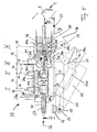
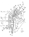
- Fig. 5 is a partially sectioned, schematic side view of a single drafting system 25 and shows its drafting device or functional parts and other details, while Fig. 6 about a section along the line VI - VI of the Fig. 5 by the drafting system 25 is.
- Fig. 6 is a partially sectioned, schematic side view of a single drafting system 25 and shows its drafting device or functional parts and other details
- Fig. 6 about a section along the line VI - VI of the Fig. 5 by the drafting system 25 is.
- the drafting 25 together with two according to Fig. 6 adjacent drafting systems 25a and 25b and possibly other, not individually shown drafting systems analogous to Fig. 1 and 2 can be summarized into a group or a bar.
- a fibrous material 27 is passed through the drafting system 25 in a direction indicated by arrows 26 transport direction.
- the drafting system 25 has four in the transport direction 26 consecutively lying pairs I, II, III and IV of drafting device organs.
- the first pair I in the transporting direction 26 and the second pair II following it in the direction of draft contain two rollers 28a, 28b or 29a and 29b, of which Fig. 5 only one roller 28a, 29a is visible.
- the following third pair III contains drafting devices 30a and 30b. of those in Fig.
- stretching rollers 31a and 31b these associated deflection elements 32a and 32b, which may consist of deflection rollers or rods, and on the deflection elements 32a, 32b and the associated rollers 31a, 31b guided straps 34a and 34b, in the In the case of double-belt drafting devices, a lower belt 34 and an upper belt 34b, between which the fiber material 27 is guided after leaving the drafting rollers 31a, 31b, are known.
- the fourth, in the transport direction 26 last pair IV again contains two drafting device in the form of a respective roller 35a and 35b.
- the axes of rotation of the rollers 31 and 35 and the axes of the deflection elements 32 are arranged perpendicular to the axes of rotation of the rollers 28 and 29. Apart from that, all four pairs I to IV define between the said rollers 28, 29, 31 and 35 usual, in Fig. 5 Dotted lines indicated by dash-dotted lines 36, 37, 38 and 39. At the entrance to the drafting 25 an inlet funnel or Trocar 40 is provided through which the fiber material 27 is fed and slightly compressed.
- the pairs I and II of the drafting device 28, 29 form a draft zone 41, wherein the peripheral speeds of the drafting system members 28, 29 z. B. are selected so that a distortion of the fiber material 27 is obtained between 5 and 15 times, which comes close to the delay in a conventional flyer.
- the fiber material 27 is subjected to a main delay between the nip lines 28 and 39 or in a zone 42, which leads to an extension of the fiber material 27 z. B. leads to 50 times or more and to a preselected final fineness.
- the described drafting system 25 has at least two pairs of drafting device elements, which bring about a folding of the fiber material 27. These are in Fig. 5 and 6 the pairs II and III, the clamping lines 37 and 38 between them Forming the folding zone 43. In contrast to the delay zones 41 and 42 takes place between the nip lines 37 and 38 only a tension distortion instead, preferably z. B. is 10% and just enough to keep the fiber material 27 stretched and to effect a defined folding.
- the center axes of the rollers 31 of the pair III are tilted or pivoted by 90 ° with respect to the center axes of the rollers 29 of the pair II.
- the center axes of the drafting device elements 28 are arranged parallel to those of the drafting device 29 and the center axes of the drafting device 35 parallel to those of the rollers 31.
- the nature of the resulting convolution depends largely on the choice of a distance D ( Fig. 5 ) between the clamping lines 37 and 38 of the drafting device organs 29, 30, which are preferably pivoted by 90 °, or the length D of the folding zone 43, as well as of a width B (FIG. Fig. 5 ) of the rollers 29a, 29b leaving fiber material 27 from.
- a distance D Fig. 5
- width B FIG. Fig. 5
- the convolution form is a function of the distance D and the width B.
- the distance D and the width B are set that results in a W-shaped fold and the original width B of the fiber material of z. B.
- Fig. 5 and 6 especially important that the axes of the input rollers 28a, 28b are perpendicular to the axes of the output rollers 35a, 35b. Therefore, it is in principle indifferent whether the distance D and the width B of the fiber material 27 in Fig. 5 and 6 are selected so that the folding described results, or whether the perpendicular arrangement of the axes is used for other purposes, as explained in more detail below.
- Fig. 6 shows that the drafting systems 25a and 25b are formed substantially the same as the drafting system 25 and the overall arrangement is analogous to Fig. 1 and 2 especially suitable for a bar-shaped grouping.
- the three drafting units 25, 25a and 25b are adjacent.
- groups with only two or even more than three adjacent drafting systems could be provided.
- the drafting systems 25, 25a and 25b preferably differ from one another by the relative positions of their rollers 28, 29.
- the drafting units 25a and 25b have - as seen in the transport direction 26 - each on the left, shown by double circles top rollers 28b, 29b and right lower rollers 28a, 29a, while in the middle drafting 25 reversely the bottom rollers 28a, 29a left and the top rollers 28b, 29b are on the right. Therefore, and because the rollers 28, 29 during operation z. B. are vertical, the rollers 31, 35, however, are arranged horizontally, the terms "lower roller” and “upper roller” are misleading, since they are no longer, as is customary exclusively in the spinning technology, the "lower” or "upper” position specify.
- the lower rollers 28a, 29a, 31a, and 35a are generally referred to as the driving rollers, and the upper rollers 28b, 29b, 31b, and 35b are referred to as the driven rollers.
- the rollers 28b, 29b, 31b and 35b usually have no own drive, but in a known manner by means of components in the form of conventional pressure arms 44 (FIG. Fig. 6 ) or 19 ( Fig. 1 and 4 ) and a z. B. elastic or pneumatic force against associated driving rollers 28a, 29a, 31a and 35a pressed and offset by frictional force of these in turns.
- the driving rollers 28a, 29a, 31a and 35a each have a positive drive. This is z. In Fig. 5 indicated.
- the driving rollers 28a, 29a are here rotatably mounted with shafts 45a, 45b in a bearing block or housing 46, and the shafts 45a, 45b are z. B. with timing pulleys, gears od. Like. Provided od with timing belt, other gears od. Like. In engagement and can be offset by these drive motors not shown in turns.
- the rollers 31a and 35a can be driven. As Fig. 6 shows, it is also analogous to the embodiment of Fig.
- Fig. 6 is the distance between the individual drafting units 25, 25a and 25b selected transversely to the transport direction 26 so that the driven rollers 28b, 29b carrying pressure arms 44 each mounted in a housing 46, such as the rollers 28, 29 vertical pivot pin 48 in the direction of Double arrow x can be swiveled to the side or alternatively opened and closed.
- the drafting 25, 25a, 25b therefore analogous to Fig. 3 and 4 arranged so that the axes of the input rollers 28a, 28b are vertical, then all the pressure arms 44 as in Fig. 4 arranged not only in the grip area of the operator 5, but are actuated by this without leaving the working space 4.
- FIG. 5 shows Fig. 5 in that the driven roller 35b is rotatably mounted on a further component in the form of an arm 50, which is mounted pivotably with a pivot pin 51 on a part of the housing 46 which lies very far in the transport direction 26.
- the pivot axis is arranged parallel to the axis of rotation of the roller 35b. Therefore, the roller 35b in FIG Fig. 5 down according to a double arrow y from the drafting system 25 are pivoted out in a dash-dotted line indicated position in which the functional part 35b and the exit slit between the straps 34a, 34b are accessible.
- the assemblies carrying the straps 34a, 34b are also mounted on a pivotable arm 52.
- the arm 52 is pivotably mounted on a rear part of the housing 46, which is opposite to the arm 50, by means of a further pivot pin 53 whose pivot axis extends parallel to the pivot axis of the pivot pin 51. Therefore, the arm 52 and with it the strap assemblies corresponding Fig. 5 swung back and forth in the direction of a double arrow z and for replacing the straps 34a, 34b.
- the arrangement is chosen so that the arm 50 in the counterclockwise direction and the arm 52 is pivotable in the clockwise direction in the open position; so that first the roller 35b and then without obstruction, the strap assembly can be pivoted into the open position.
- the arms 50, 52 are otherwise, as not shown in detail, formed by means of springs, pneumatic or otherwise as pressure arms od the mounted on them, driven rollers od. Like. Od against the associated, driving rollers. The like. Press ,
- the drafting device 25 is preferably arranged at an angle between 90 ° and 180 ° relative to the knitting needles 30, so that about the Fig. 1 for the drafting 8 apparent skewing results.
- the pair I of the input rollers 28a, 28b is disposed slightly higher than the pair IV of the output rollers 35a, 35b above the head of the operator 5. This can therefore with simple handles and without leaving the working space 4 optionally the pressure arms 44 to the side and / or the arms 50, 52 pivot down to open the drafting system 25.
- Fig. 6 shows, also for the other drafting systems 25a and 25b.
- the two rollers 31a and 31b, over which the straps 34a, 34b run not shown, for.
- a location 54 e.g. Fig. 5
- the driving roller 31a of the (lower) strap 34a in Fig. 5 expediently driven by means of a toothed belt indicated by arrows r , which is placed around a toothed belt pulley 55 whose axis of rotation coincides with the pivot axis of the pivot pin 53.
- the toothed belt pulley 55 is preferably mounted on a shaft projecting through the entire drafting group, perpendicular to the input rollers 28a, 28b, from which the drives for the rollers 31a of the other drafting arrangements 25a, 25b, etc. are also derived.
- rollers 31a, 31b circumferentially with radial pins 56 (FIG. Fig. 6 ), which engage in holes 57 which are attached to the edges of the straps 34a, 34b and arranged one behind the other in the transporting direction 26. This makes it possible to drive both straps 34a, 34b forcibly and completely without slippage, which promotes a uniform refinement of the fiber material 27.
- a suction / blowing air device can be provided to od the drafting device 25 largely free of lint.
- a suction / blowing air device can be provided to od the drafting device 25 largely free of lint.
- the rollers 35a, 35b remain largely free of lint.
- the exiting blown air flow is directed onto the return runs of the straps 34a, 34b via patches 59 which are arranged on the back of the rollers 35a, 35b near the exit gap between the straps 34a, 34b and which serve to optimize the blowing air flow. From there, the air flow through air channels 60 and 61, which are formed on the bottom and top of the drafting 25 enveloping housing 46 and in which there is advantageously a slight negative pressure, fed to a central exhaust.
- the air channel 60 As separating points 60a in a front and rear portion indicate a central portion 60b which is fixed to the arm 52 so that it can be pivoted together with this and the strap assemblies in the direction of the arrow z from the housing 46 ( Fig. 5 ).
- the patches 59 are suitably mounted on the arm 50 or 52 so that they do not interfere with their pivoting movements.
- Fig. 6 shows Fig. 6 in that two further patches 62 are arranged in each case between the rollers 28a, 29a and 28b, 29b in the pre-draft zone 41, which form guide channels 63 for the fiber material 27 between them.
- the automatic threading the fiber material 27 is substantially facilitated in the largely closed drafting system 25.
- a distance measure 64 in Fig. 6 in that the guidance of the folded fiber material 27 by the pair of rollers IV is expediently not exactly centered in comparison to the course of the fibers in the roller pairs I and II. Because the rollers 35b (usually coated with a rubber layer) Fig. 5 ) because of the high speeds of z. B. 2000 rpm to 4000 rpm are subject to a certain wear, the rollers 35b can be turned if necessary. As a result, the running time of the rollers 35b can be doubled even without costly traversing.
- the drafting can after Fig. 5 and 6 are also arranged in a pivoted about 90 ° about the longitudinal axis position and so that the arms 50, 52 can pivot to the side and the pressure arms downwards.
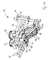
- Fig. 7 shows a further embodiment of an inventive drafting system 65, which is analogous to Fig. 3 and 4 especially suitable for a segmental construction, in which the number of combined drafting units to a unit in comparison to the billet solution after Fig. 1 and 2 is relatively low and z. B. is two.
- the drafting system 65 largely corresponds to the drafting 25 after Fig. 5 and 6 , differs from this but by a characteristic angling or skewing of a main drafting zone 66 in the region of a bend K.
- the functional parts in a Vorverzugszone 67 and a folding zone 68 are in Fig. 7 largely identical to Fig. 5 and 6 designed and arranged and therefore provided with the same reference numerals.
- the fiber materials 27 are therefore as parallel to the ground 7 (FIG. Fig. 1 and 3 ) and perpendicular to the knitting needles 3 are passed through the pre-warp and fold zones 67, 68 before being inserted into apron assemblies 69a, 69b.
- Each two straps 70a and 70b of these assemblies 69a and 69b are placed around two rollers 71a, 71b and two deflecting elements 72a, 72b and form between them guide tracks 73, which at the exit of the rollers 29a, 29b approximately at the height of the predetermined by the transport direction 26 web begin and then extend obliquely downwards in the direction of the lower deflecting elements 72a, 72b.
- the inclination angle is z. B.
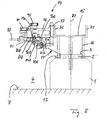
- FIG. 8 Another embodiment of a drafting system 74 according to the invention which is particularly expedient for practical application results from 8 to 12 ,
- Fig. 8 is the support ring 15 of the corresponding Fig. 1 trained circular knitting machine 1 is provided at its outer periphery with vertical mounting plates 75, which serve a plurality of draw frames 74 for attachment.
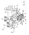
- Each drafting system 74 has for this purpose on a front side of a drafting device housing 76 a flange plate 77 (see in particular Fig. 11 ), which is fastened with fastening screws 78 and dowels 79 on one of the mounting plates 75.
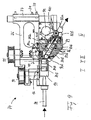
- the drafting system 74 is analogous to Fig. 7 constructed and according to Fig. 9 to 12 provided with four pairs I to IV of drafting organs.
- the first pair I includes two input rollers 80a and 80b which form a pre-delay zone with rollers 81a, 81b of the second pair II, while the fourth pair IV includes two output rollers 82a, 82b.
- the rollers 80a, 80b and 81a, 81b are vertical, while the rollers 82a, 82b are horizontal.
- two strap assemblies 83a and 83b are arranged, analogous to Fig.
- rollers 84a and 84b these associated, not shown deflection elements and guided on these straps 85a and 85b have.
- the rollers 84a, 84b form analogously to Fig. 7 with the rollers 81a, 81b, a folding zone and are therefore arranged horizontally in operation as the output rollers 82a, 82b and the deflecting elements, not shown.
- the straps 85a, 85b form between them a guide track 86 (FIG. Fig. 9 ), which like the guideway 73 in Fig. 7 obliquely to a rotation axis 87 (FIG. Fig. 8 ) of the needle cylinder 2 and to the knitting needles 3 is arranged.
- a feed hopper or trocar 88 is inserted through the fiber material, not shown in the nip between the input rollers 80a, 80b.
- the conditions according to the above explanations are chosen so that the fiber material in the folding zone between the rollers 81a, 81b and 84a, 84b z. B. V-, N- or W-shaped, before it is fed by means of the straps 85a, 85b the exit gap between the output rollers 82a, 82b and is subjected to this of the main delay.
- the fiber material emerging from the outlet gap is then preferably conveyed by means of a spinning device 21 (cf. Fig. 4 . 7 and 8th ) or another spin organ is converted into a temporary yarn and transported to the knitting needles 3.
- a special feature of the drafting system 74 is that it can be at least partially opened by the fact that at least the apron assemblies 83 completely formed on a cassette-shaped, in Fig. 9 . 9a . 11 and 12 are made visible by hatching made more visible component in the form of an insertion part 89.
- This insertion part 89 is seated in a downwardly open recess 90 (FIG. Fig. 9a ) of the housing 76 and has z. B. - considered in the transport direction of the fiber material - as front and rear boundaries respectively guide surfaces 90a ( Fig. 9a ), which with corresponding, the recess 90 limiting guide surfaces 90 b ( Fig. 8 . 9 and 9a ) interact.
- the guide surfaces 90b stand as Fig.
- the housing 76 and the insertion part 89 with cooperating, omitted for clarity overview locking means and possibly also with other positioning means can be provided to the insertion part 89 in the off Fig. 9 correct working position in the drafting system 74 correctly position and set.
- the preferred in Fig. 9 lower, driven output roller 82b also mounted on the insertion part 89 (see. Fig. 9a ) so that their position relative to the driven strap 85b can be adjusted easily with the insertion part 89 pulled out.
- the insertion part 89 may be provided with spring elements, not shown, or the like, in order to press the driven strap assemblies 83b against the driving strap assemblies 83a.
- each drafting system 74 analogous to Fig. 3 preferably two drafting sections arranged in tandem construction next to each other. Therefore, the drafting system 74, two inlet funnel 88, two pairs of input rollers 80a and 80b, two straps 85a, 85b, etc., so that at the same time two fiber materials refined in parallel operation and adjacent knitting points of the circular knitting machine 1 can be supplied.
- the driven rollers 80b of the pairs I are expediently respectively arranged on the outside of the housing 76 and there on pivotally mounted pressure arms 91 (eg. Fig. 10 and 11 ) rotatably mounted.
- the pressure arms 91 can be fixed in a manner known per se to vertical pivot pins 92 (FIG. Fig.
- the functional parts are made accessible in that the insertion part 89 pulled down and / or the pressure arms 91 are pivoted to the side. If it is desired to make available at least the driven output rollers 82b independently of the other functional parts, they can be analogous to Fig. 7 be mounted on a separate, downwardly pivoting arm.
- the pressure arms 91 may also be correspondingly Fig. 4a and 4b be formed.
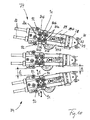
- Fig. 10 shows that the drafting units 74 can be arranged very close to each other. Because of the segmented construction described, they lie radially to the central axis 87 (FIG. Fig. 8 ) of the needle cylinder 2 and therefore have, where the threads emerge, their smallest distance a , while they have, where the fiber materials are supplied, larger distances b . This allows in connection with the tandem design, despite the fact that the pressure arms 91 must be pivoted to the side, a comparatively large packing density of the drafting units 74 on the circumference of the needle cylinder 2, with the result that the spinning devices 21 (FIGS. Fig. 3 ) Even when the knitting machine 1 is provided with 72 or even 96 knitting points, only relatively short transport tubes 23 require and only a single twisting element 22 is required, which brings a significant energy savings.
- the drive for the driving rollers 80a, 81a of the first and second pair I and II takes place in the embodiment of 8 to 12 by means of vertical drive shafts, are wound on the pulleys 94, 95.
- only one drive motor is therefore ever required.
- the desired transmission ratio and the required direction of rotation can be achieved with the aid of spur gears 96, 97 (FIG. Fig. 9 ).
- the drive for the driving rollers 84a of the strap assemblies 83a by means of in Fig.
- the driving rollers 82a of the output roller pair IV would, if they are to be driven by means of vertical standing waves, also be coupled via bevel gears with these waves. In view of the high rotational speeds of these rollers 82a, 82b, this could lead to problems or require costly gearboxes. According to the invention, it is therefore proposed to provide the driving output rollers 82a of the folding drafting systems 25, 65 and 74 with drives assigned to them individually. This is in Fig. 9 and 9a indicated schematically, wherein in the housing 76, a motor 99 is housed, which is drivingly coupled via a toothed belt 100 with a toothed belt pulley, which sits on the shaft of the driving output roller 82a. Of course, with the same motor 99 both (or more) pairs of output rollers IV can be driven when the drafting units 74 are in the same position as in FIG 8 to 12 are arranged for the parallel processing of two (or more) fiber materials.
- Fig. 13 shows as an exemplary embodiment, a 3-roller drafting system 102 accordingly Fig. 3 with two parallel working drafting sections, each a pair of I, II and III of drafting system organs, wherein in Fig. 13 in each case only one of the pairwise existing drafting system organs is visible.
- Each drafting section includes two input rollers 103, two output rollers 104 and between each two slip assemblies 105 each having a roller 106. All drafting elements have as in Fig. 3 arranged parallel to each other and during operation vertical axes of rotation, as indicated in each case by dotted lines.
- a nozzle 107 which consists essentially of a closed housing in which other functional parts not shown, for blowing the output rollers 104 certain air nozzles, also suction channels for loose fibers and air ducts for the pneumatic twist elements 22nd the spinning devices 21 can be accommodated.
- the strap assemblies 105 and the nozzle assembly 107 are each formed as insertion parts 108, 109, which can be pulled out in the direction of arrows u down from the drafting system 102.
- the formation of the insertion parts 108, 109 can analogously to Fig. 9 and 9a be elected.
- coupling 110 for the insertion part 108 shows the strap assemblies 105 can be decoupled when pulling out of the insertion part 108 of overlying drive members whose axes are parallel to those of the rollers 106.
- the input rollers 103 and the output rollers 104 may each be arranged in a respective insertion part 103a, 104a, which is connected to a further coupling 110 to the drive or decoupled from this.
- the driven rolls of the pair I also in analogy in 8 to 12 mounted on a common, not shown, pivotable to the side of the pressure arm, which could also be replaced by two individual pressure arms.
- Fig. 14 is different from that Fig. 13 in that it can be used as a 4-roller folding drafting device 111 without kink K (FIG. Fig. 7 ) is trained.
- horizontal input rollers 112 of the first pair I and with these the Vorverzugszone forming during operation also horizontal rollers 113 of the second pair II in a insertion part 114 forming cassette are arranged.
- the axes of the input rollers 112 and the rollers 113 of the pair II are horizontal here, the axes of the belt assemblies 115 and of output rollers 116, however, arranged vertically. Therefore, the driving rollers of the pairs I and II, as in Fig. 9 is indicated for the rollers 84a, for example, driven by means of bevel gears 117, 118, which mesh with sitting on the shafts 112, 113 further bevel gears and at the same time serve as couplings when pulling out or insertion of the insertion part 114. As a result, the rollers 112, 113 are automatically coupled with the movements of the insertion part 114 with a non-illustrated, explained below drive or decoupled from these.
- the driven drafting devices of the apron assemblies 115 and the exit rollers 116 may be analogous to Fig. 4 to the sides of the drafting system 111 swing away pressure arms od. Like. Be stored. A particularly preferred Aus Shebrungsform results, however, if the apron assemblies 115 and the output rollers 116 analogous to Fig. 13 be attached to insertion parts 115b and 116a; which can be pulled down in the direction of arrows 1 down.
- Fig. 15 shows a 4-roller drafting system 119, which is currently considered to be the best embodiment of the invention and from the Fig. 14 in that the axes of input rollers 120, apron rollers 121 and exit rollers 122 are all arranged vertically during operation, while further rollers 123 arranged between the input and apron rollers 120, 121 have horizontal axes.
- An advantage of the drafting system 119 after Fig. 15 is that in operation, the axes of the rollers 123 can be arranged horizontally, all other rollers, however, vertically, as it is for reasons of a simplified drive, as explained below, is preferred.
- the horizontal rollers 123 and possibly the Leirtiata 124 are housed in an insertion part 125 which can be pulled out in the direction of an arrow m down from the drafting system 119, as is also true for the remaining functional parts. Therefore, here are all the rollers of the pairs I, II, III and IV at the off FIGS. 13 and 14 apparent insertion parts od.
- the insertion part 125 and the rollers 123 associated bevel gear 126 is required, which also serves as a coupling, while all other insertion parts are coupled via the couplings 110 to the drive.
- a drafting device 127 which is provided in the region of the pairs I and II with vertically arranged rollers 128 and 129. Furthermore, the drafting device 127 analogously Fig. 15 in the region of drafting device organs III and IV, two pairs of apron assemblies 130 and output rollers 131, whose axes are also arranged vertically during operation. Between the drafting pairs II and III, however, an additional pair V of drafting system members is provided, consisting of horizontally arranged rollers 132. On the one hand, the ratios are selected so that the rollers 129 and 132 a folding zone in the sense of the folding zone 43 after Fig. 5 form by z. B.
- the initial width of the sliver in the nip of the rollers 129 to 16 mm and the distance of the nip lines between the rollers 129 and 132 is set to about 30 mm, so that there is a W-shaped fold and that the rollers 132nd leaving sliver only has a width of about 4 mm.
- the distance between the nip lines of the rollers 132 and the rollers 133 of the apron assembly 130 with eg also 30 mm compared to the only about 4 mm wide sliver set so large that there is no re-folding.
- the guide plates 124 after Fig. 15 to arrange appropriate baffles.
- the drafting device 127 can be realized simply by additionally installing the rollers 132 between the rollers of the second and third pairs of a conventional 4-roller drafting system.
- the drive of the drafting systems described can be made in a usual way in drafting equipment.
- the like. are provided (eg 94, 95 in Fig. 9 ).
- the timing pulleys 140 on the shafts of the driving input rollers eg, 112, 120, 128, the timing pulleys 141 on the shafts of the driving pulley drive rollers (eg, 115a, 121, 133), and the toothed pulleys 142 on the shafts Waves of the driving output rollers (eg 116, 122, 131) are attached.
- Each toothed belt 137, 138 and 139 regardless of the number of existing knitting need only ever a schematically indicated drive motor 143, 144 and 145 and if necessary ever a tension roller assigned.
- the horizontal drafting device can be driven mainly with the same drive motors. These are in Fig. 14 z. B. on the shafts of the rollers 115 a additional spur gears 146 attached, which mesh with other spur gears 147 which are mounted on the shafts of the bevel gears 118. A corresponding arrangement is in Fig. 15 shown. On the other hand shows Fig. 16 in that two further spur gears 147 and 148 can mesh with the spur gear 146, the spur gear 147 for driving the horizontal rollers 132 with the aid of a bevel gear 126 (FIG. Fig. 15 ) corresponding bevel gear 134 and the spur gear 148 for direct drive of the vertical rollers 129 is used. According to the embodiment Fig. 13 are only two timing belts and drive motors required because the rollers 103 and 106 here z. B. by spur gears 150, 151 can be coupled to a drive shaft of the rollers 106.
- Fig. 13 to 16 in that, in all cases, components designed either as insertion parts 108, 109, 114, 115b, 116a, 125 and 135 or as pressure arms can be provided in order to be analogous to Fig. 1 . 3 and 8th to make all essential functional parts accessible from the working space 4.
- Fig. 10 near the knitting points especially small distances a of z. B. a few millimeters between the drafting units are desirable, since in such a case to the side swivel or sliding parts would hinder a close arrangement of the drafting systems.
- an insertion part 153 is in Fig. 18 shown. It includes a in the view H-shaped housing 154 which od at the tops of long legs 154 a with screw holes, threaded holes 155 or the like. Is provided. In a short transverse web 154b of the H-shaped housing 154, two shafts extending parallel to the legs 154a are rotatably mounted. On these waves is on both sides of the crosspiece 154b z. B. one each for driving a belt 156a, 156b certain roller 157a, 157b or 158a, 158b attached, and the straps 156a, 156b (the second pair of straps is in Fig. 18 not visible) are guided as usual by these rollers and two spaced apart from these deflecting elements 159, as in Fig. 18 is clearly visible for the pair of straps 156a, 156b.
- Fig. 18 further shows that z. B. the roller 157 a or the shaft is longer than the adjacent roller 157 b or the shaft is formed and z. B. the top of the legs 154a, 154b with a z. B. four- or hexagonal coupling pin 160 surmounted.
- This coupling pin 160 further penetrates z. B. a cover plate 161 ( Fig. 13 ) at the upper end of the drafting housing.
- a cover plate 161 at the lower end of one of these strap assembly associated drive shaft 162
- a four- or hexagonal certain for rotationally fixed receiving the coupling pin 160 and attached to this open coupling sleeve 163 attached. Is therefore z. B.
- the parts 160 and 161, the in Fig. 13 to 15 represent schematically indicated couplings 110, automatically separated from each other.
- the arrangement is such that upon retraction of the insertion part 153 in the drafting housing automatically the coupling pin 160 enters the coupling sleeve 163 and thereby connects the Riemchen- assembly with the associated drive. After the application of the housing 154 to the cover plate 161, it is fastened with fastening screws screwed into the bore 155.
- insertion parts with vertically arranged functional parts can be designed accordingly, wherein the straps are missing depending on the case.
- such insertion parts can be provided, which are provided with horizontal functional parts (eg, 123 in Fig. 15 ).
- horizontal functional parts eg, 123 in Fig. 15 .
- Fig. 18 shows Fig. 18 in that, according to the tandem construction described above above, the insertion part 153 has a double strap assembly above and below the transverse web 154b.
- the shafts or drive rollers of these modules are each only one side, ie on the side of the crosspiece 154b and thus cantilevered so that the run from them straps are deducted after removal of the insertion part 153 from the drafting up or down and replaced can.
- the insertion parts 153 can be provided with resilient elements or the like, which push the driven straps 156b against the driving straps 156 during operation.
- the invention is not limited to the described embodiments, which can be modified in many ways. This applies in particular to the expressions "vertical” and “horizontal”, since also positions of the various functional parts are possible with different axes during operation.
- the axes of the drafting rollers 18 could be in Fig. 1 Also be arranged at angles between 0 ° and 90 ° to the central axis of the needle cylinder 2.
- pivot arms and insertion parts represent only examples of which can be deviated in many ways, and that in particular the insertion parts may be provided with means not shown in detail in order to operate the driven rollers and straps resiliently or pneumatically against the driving rollers and straps to press.
- functional parts could also be provided laterally extendable insertion parts.
- the functional parts to be serviced and, if necessary, frequently replaced are preferably mounted on or in the pivotable arms, insertion parts, etc., so that they can easily be exchanged in the opened state.
- Fig. 3 . 6 and 18 the rollers and deflection elements eg 31, 32 in Fig.
- the number of pairs of drafting devices used per drafting system may vary depending on the particular case, ie, 3, 4, 5-roll drafting devices, etc. may be provided.
Landscapes
- Engineering & Computer Science (AREA)
- Textile Engineering (AREA)
- Mechanical Engineering (AREA)
- Spinning Or Twisting Of Yarns (AREA)
- Knitting Of Fabric (AREA)
- Knitting Machines (AREA)
- Treatment Of Fiber Materials (AREA)
Abstract
Claims (17)
- Machine pour fabriquer un article maille en utilisant au moins pour partie une matière fibreuse (10, 27), comprenant une multiplicité de points (6) de formation de mailles et de bancs d'étirage (8, 8b, 25, 65, 74, 102, 111, 119, 127) présentant des parties fonctionnelles (18, 28-30, 35, 59, 60b, 80-83, 103-105, 107, 112, 113, 115, 116, 120-123, 128-133, 156-159) et associés au moins à des points sélectionnés (6) de formation de mailles, pour produire des fils (11) formés à partir de la matière fibreuse (10, 27), caractérisée en ce qu'au moins des parties fonctionnelles sélectionnées (18, 28-30, 35, 59, 60b, 80-83, 103-105, 107, 112, 113, 115, 116, 120-123, 128-133, 156-159) sont montées sur des éléments structurels (19, 44, 50, 52, 89, 91, 108, 109, 114, 125, 135, 153) supportés sur les bancs d'étirage (8, 8b, 25, 65, 74, 102, 111, 119, 127) de telle sorte qu'ils peuvent être écartés par pivotement ou traction vers le côté ou vers le bas.
- Machine selon la revendication 1, caractérisée en ce que les bancs d'étirage (8, 8b, 25, 65, 74, 102, 111, 119, 127) sont disposés au-dessus des points (6) de formation de mailles, mais à portée d'un opérateur (5) travaillant sur la machine.
- Machine selon la revendication 1 ou 2, caractérisée en ce qu'elle est réalisée sous la forme d'un métier à tricoter circulaire (1) doté d'un cylindre à aiguilles (2) et d'aiguilles à tricoter (3), et les bancs d'étirage (8, 8b, 25, 65, 74) sont disposés au-dessus du cylindre à aiguilles (2), mais à portée de l'opérateur (5).
- Machine selon l'une des revendications 1 à 3, caractérisée en ce que les parties fonctionnelles (18, 28-30, 35, 59, 60b, 80-83, 103-105, 107, 112, 113, 115, 116, 120-123, 128-133, 156-159) sont constituées d'organes de banc d'étirage, et les éléments structurels (19, 44, 50, 52, 89, 91) de bras qui peuvent pivoter vers le bas ou vers le côté.
- Machine selon la revendication 3 ou 4, caractérisée en ce que les bancs d'étirage (8) sont disposés perpendiculairement ou en oblique par rapport à un axe médian (87) du métier à tricoter circulaire (1).
- Machine selon l'une des revendications 1 à 5, caractérisée en ce qu'une pluralité de bancs d'étirage (8b, 74) sont disposés en étoile et en étant répartis radialement sur la périphérie du cylindre à aiguilles (2), par rapport à l'axe médian (87).
- Machine selon l'une des revendications 1 à 5, caractérisée en ce que plusieurs bancs d'étirage (8) de même type sont disposés en forme de barre et horizontalement les uns derrière les autres.
- Machine selon l'une des revendications 1 à 7, caractérisée en ce que les bancs d'étirage (8b) comprennent des organes de banc d'étirage (18, 18a) ayant des axes s'étendant verticalement ou en oblique par rapport à la verticale, et au moins certains de ces organes de banc d'étirage (18a) sont montés sur un élément structurel réalisé sous forme de bras de pression (19) pouvant être écarté par pivotement vers le côté.
- Machine selon la revendication 8, caractérisée en ce que les bancs d'étirage (8b) sont disposés en forme de segment et présentent chacun au moins deux sections de banc d'étirage de même type, dotées d'organes de banc d'étirage (18, 18a) disposés par paires coaxialement l'un au-dessus de l'autre, sachant que les organes de banc d'étirage menés (18a) sont montés sur un bras de pression commun (19).
- Machine selon l'une des revendications 1 à 5, caractérisée en ce que les bancs d'étirage (8) sont disposés en forme de barre et comprennent chacun au moins deux organes de banc d'étirage (18) ayant des axes s'étendant horizontalement, sachant qu'au moins certains des organes de banc d'étirage (18a) sont montés sur un élément structurel réalisé sous forme de bras de pression (19) pouvant être écarté par pivotement vers le bas.
- Machine selon l'une des revendications 1 à 10, caractérisée en ce que les bancs d'étirage sont réalisés sous la forme de bancs d'étirage plieurs (25, 65, 74, 111, 119, 127), qui présentent au moins quatre paires (I à V) d'organes de bancs d'étirage (28, 29, 30, 35 ; 28, 29, 69, 35 ; 80-83, 103-105, 107, 112, 113, 115, 116, 120-123, 128-133, 156-159), sachant que, considéré dans une direction de transport (26) pour la matière fibreuse (27), une première paire (I) et une deuxième paire (II) forment une zone d'étirage préparatoire (41, 67), la deuxième paire (II) et une troisième paire (III, V) forment une zone de pliage (43, 68), et la troisième paire (III, V) et une quatrième paire (IV) forment une zone d'étirage principal (62, 66).
- Machine selon la revendication 11, caractérisée en ce qu'au moins les organes de banc d'étirage (30, 69, 83, 115, 130) de la troisième paire (III) comprennent chacun un cylindre (31, 71, 84, 115a, 121, 133), un élément de déviation (32, 72) et un manchon (34, 70, 85).
- Machine selon la revendication 12, caractérisée en ce qu'au moins les organes de banc d'étirage menés (30, 69, 83, 115, 130) de la troisième paire (III) sont montés sur un élément structurel sous la forme d'un bras de pression (19, 44, 91) pouvant être écarté par pivotement vers le bas ou vers le côté.
- Machine selon la revendication 13, caractérisée en ce que les organes de banc d'étirage menés (30b, 69b) de la troisième paire (III) sont montés sur un premier bras (52), et un organe de banc d'étirage mené (35b) de la quatrième paire (IV) est monté sur le même bras ou sur un deuxième bras (50) séparé du premier.
- Machine selon la revendication 12, caractérisée en ce qu'au moins les organes de banc d'étirage (83a, 83b, 105, 115, 130) de la troisième paire (III) sont montés sur un élément structurel réalisé sous la forme d'une pièce d'insertion (89, 108) pouvant être écartée du banc d'étirage (74, 102, 111, 119, 127) par traction vers le côté ou vers le bas.
- Machine selon la revendication 15, caractérisée en ce que la quatrième paire (IV) présente des organes de banc d'étirage menant et mené (82a, 82b), et l'organe de banc d'étirage mené (82b) est monté sur la pièce d'insertion (89).
- Machine selon l'une des revendications 5 à 16, caractérisée en ce que les pièces d'insertion (89, 108, 114, 135), au moins dans la mesure où elles présentent des parties fonctionnelles menantes (84, 104, 106, 112, 113, 115a, 116, 120, 121, 122, 123, 132), sont couplées au moyen d'accouplements à des éléments d'entraînement (140, 141, 142) associés au banc d'étirage (74, 102, 111, 119, 127).
Applications Claiming Priority (2)
| Application Number | Priority Date | Filing Date | Title |
|---|---|---|---|
| DE102006006502.6A DE102006006502B4 (de) | 2006-02-13 | 2006-02-13 | Spinnstrickmaschine |
| PCT/DE2007/000286 WO2007093165A2 (fr) | 2006-02-13 | 2007-02-13 | Machine permettant de fabriquer des tissus maillés en matière fibreuse, en particulier métier à tricoter circulaire |
Publications (2)
| Publication Number | Publication Date |
|---|---|
| EP1984549A2 EP1984549A2 (fr) | 2008-10-29 |
| EP1984549B1 true EP1984549B1 (fr) | 2012-06-27 |
Family
ID=38115469
Family Applications (2)
| Application Number | Title | Priority Date | Filing Date |
|---|---|---|---|
| EP07711190A Not-in-force EP1984549B1 (fr) | 2006-02-13 | 2007-02-13 | Machine permettant de fabriquer des tissus maillés en matière fibreuse, en particulier métier à tricoter circulaire |
| EP07711191A Not-in-force EP1984550B1 (fr) | 2006-02-13 | 2007-02-13 | Métier à tricoter circulaire pour la fabrication de tissus maillés à partir de matière fibreuse |
Family Applications After (1)
| Application Number | Title | Priority Date | Filing Date |
|---|---|---|---|
| EP07711191A Not-in-force EP1984550B1 (fr) | 2006-02-13 | 2007-02-13 | Métier à tricoter circulaire pour la fabrication de tissus maillés à partir de matière fibreuse |
Country Status (7)
| Country | Link |
|---|---|
| US (1) | US7926306B2 (fr) |
| EP (2) | EP1984549B1 (fr) |
| CN (1) | CN101400837B (fr) |
| DE (1) | DE102006006502B4 (fr) |
| ES (1) | ES2412329T3 (fr) |
| PL (1) | PL1984550T3 (fr) |
| WO (3) | WO2007093167A1 (fr) |
Families Citing this family (26)
| Publication number | Priority date | Publication date | Assignee | Title |
|---|---|---|---|---|
| DE102006037714A1 (de) * | 2006-08-07 | 2008-02-14 | Wilhelm Stahlecker Gmbh | Vorrichtung zum Herstellen einer Maschenware |
| WO2008067804A1 (fr) * | 2006-12-03 | 2008-06-12 | Koenig Reinhard | Métier à tricoter circulaire pour fabriquer des articles maille en utilisant un matériau fibreux non tordu |
| WO2008086791A1 (fr) * | 2007-01-17 | 2008-07-24 | Koenig Reinhard | Machine de production de tissu maille et son procédé de mise en service |
| DE102007004441A1 (de) | 2007-01-25 | 2008-07-31 | Sipra Patententwicklungs- Und Beteiligungsgesellschaft Mbh | Maschine zur Herstellung einer Maschenware aus Fasermaterial, insbesondere Strickmaschine |
| DE102007027467A1 (de) | 2007-06-14 | 2008-12-18 | König, Reinhard, Dr. Ing. | Maschine zum Spinnen und Stricken sowie ein Verfahren |
| DE102007039870A1 (de) * | 2007-08-21 | 2009-02-26 | Sipra Patententwicklungs- Und Beteiligungsgesellschaft Mbh | Vorrichtung zum Transport von Fasermaterial zwischen einem Streckwerk und einer maschenbildenden Maschine und damit ausgerüstete Rundstrickmaschine |
| DE102007041171A1 (de) | 2007-08-28 | 2009-03-05 | Sipra Patententwicklungs- Und Beteiligungsgesellschaft Mbh | Verfahren und Strickmaschine zur Herstellung einer Maschenware aus im wesentlichen unverdrehtem Fasermaterial |
| WO2009026734A1 (fr) * | 2007-08-31 | 2009-03-05 | Rotorcraft Ag | Unité d'étirage pour une machine à tricoter |
| TWI471469B (zh) * | 2007-10-02 | 2015-02-01 | Rotorcraft Ag | 用於製造針織布的方法和裝置 |
| DE102007051655B4 (de) | 2007-10-26 | 2019-10-17 | Wilhelm Stahlecker Gmbh | Verfahren zur Herstellung einer Maschenware und Vorrichtung zum Spinnstricken mit einem Streckwerk |
| DE102007052548A1 (de) | 2007-10-30 | 2009-05-14 | Sipra Patententwicklungs- Und Beteiligungsgesellschaft Mbh | Vorrichtung zur Zuführung von Fasermaterial zu einerFaser verarbeitenden Maschine |
| DE102007052549A1 (de) * | 2007-10-30 | 2009-05-20 | Sipra Patententwicklungs- Und Beteiligungsgesellschaft Mbh | Maschine zur Herstellung von Maschenware unter zumindest teilweiser Anwendung von Fasermaterial |
| WO2009059438A1 (fr) * | 2007-11-06 | 2009-05-14 | Rotorcraft Ag | Métier à tricoter et procédé de fabrication de tricots à partir de mèches de préparation |
| DE102008008211B4 (de) | 2007-12-06 | 2012-01-26 | Sipra Patententwicklungs- Und Beteiligungsgesellschaft Mbh | Verfahren und Strickmaschine zur Herstellung einer Maschenware aus einem ungedrehten Fasermaterial |
| DE102008008210B4 (de) | 2007-12-06 | 2013-07-18 | Sipra Patententwicklungs- Und Beteiligungsgesellschaft Mbh | Verfahren und Rundstrickmaschine zur Herstellung einer Maschenware aus einem ungedrehten Fasermaterial |
| DE202008001797U1 (de) | 2007-12-20 | 2009-06-10 | Sipra Patententwicklungs- Und Beteiligungsgesellschaft Mbh | Maschine zur Herstellung von Maschenware unter zumindest teilweiser Anwendung von Fasermaterial |
| DE102011053396B3 (de) * | 2011-09-08 | 2012-08-23 | Terrot Gmbh | Vorrichtung und Verfahren zur Herstellung von Maschenware |
| US9328438B2 (en) | 2011-09-21 | 2016-05-03 | Reinhard König | Folding drawing system for a spin-knit machine |
| JP6228983B2 (ja) * | 2012-09-24 | 2017-11-08 | ケーニッヒ,ラインハルト | ダブルフォールディングドラフティングユニット |
| US9222200B2 (en) * | 2012-12-19 | 2015-12-29 | Industrial Technology Research Institute | Spinning device |
| DE102013102827A1 (de) * | 2013-03-20 | 2014-09-25 | Sipra Patententwicklungs- Und Beteiligungsgesellschaft Mbh | Streckwerk für eine Strickmaschine |
| DE102013103738A1 (de) * | 2013-04-15 | 2014-10-16 | Sipra Patententwicklungs- Und Beteiligungsgesellschaft Mbh | Streckwerk für eine Strickmaschine |
| DE102014215857A1 (de) * | 2014-08-11 | 2016-02-11 | Init Innovative Informatikanwendungen In Transport-, Verkehrs- Und Leitsystemen Gmbh | Verfahren zum Leiten der Fahrgäste öffentlicher Verkehrsmittel |
| JP6164190B2 (ja) * | 2014-10-10 | 2017-07-19 | 株式会社豊田自動織機 | 紡機における特殊糸製造装置 |
| DE102015119040A1 (de) | 2015-11-05 | 2017-05-11 | Terrot Gmbh | Vorrichtung und Verfahren zur Herstellung von Maschenware |
| DE102018004982A1 (de) | 2018-06-19 | 2019-12-19 | Gebrüder Otto Baumwollfeinzwirnerei GmbH & Co. KG | Verwendung eines textilen Flächenmaterials mit Garnen mit niedrigem Drehungsbeiwert zur Herstellung von thermisch und/oder elektrisch isolierener Bekleidung |
Family Cites Families (19)
| Publication number | Priority date | Publication date | Assignee | Title |
|---|---|---|---|---|
| US3299672A (en) * | 1963-12-20 | 1967-01-24 | Arnold W Schmidt | Method and apparatus for producing knit pile fabric |
| US3226952A (en) * | 1964-08-27 | 1966-01-04 | Wildman Jacquard Co | Method of knitting pile fabric |
| GB1285054A (en) * | 1969-04-18 | 1972-08-09 | Iws Nominee Co Ltd | Improvements in the manufacture of pile fabrics |
| US3877254A (en) * | 1973-07-30 | 1975-04-15 | Stevens & Co Inc J P | Method and apparatus for knitting fabric from untwisted staple fibers |
| GB1452501A (en) * | 1973-11-02 | 1976-10-13 | York H Young B | Knitting machines |
| US4006609A (en) * | 1974-04-29 | 1977-02-08 | Bunker Ramo Corporation | Manufacturing of patterned deep pile circular knitted fabric |
| GB1538924A (en) | 1976-01-17 | 1979-01-24 | Lawson Hemphill | Machine for knitting cord-like products |
| US4245487A (en) * | 1979-06-06 | 1981-01-20 | Schaab Rudolph S | Method and apparatus for knitting sliver loop knit fabric |
| DE3247957A1 (de) * | 1982-12-24 | 1984-06-28 | Sulzer Morat Gmbh, 7024 Filderstadt | Rundstrickmaschine zur herstellung von strickwaren mit eingekaemmten fasern |
| US5134863A (en) * | 1991-05-10 | 1992-08-04 | Mayer Industries, Inc. | Circular sliver knitting machine having increased carding capacity |
| US5431029A (en) * | 1994-03-17 | 1995-07-11 | Mayer Industries, Inc. | Method and apparatus for forming reverse loop sliver knit fabric |
| US5685176A (en) * | 1995-10-06 | 1997-11-11 | Mayer Industries, Inc. | Circular sliver knitting machine |
| CN2293575Y (zh) * | 1997-04-29 | 1998-10-07 | 南通达利金属制品有限公司 | 长毛绒纬编机 |
| DE19851403B4 (de) * | 1998-11-07 | 2009-11-12 | Sipra Patententwicklungs- Und Beteiligungsgesellschaft Mbh | Rundstrickmaschine zur Herstellung von Strickwaren mit eingekämmten Fasern |
| DE19925171A1 (de) * | 1999-06-01 | 2000-12-07 | Terrot Strickmaschinen Gmbh | Rundstrickmaschine |
| DE10251727A1 (de) * | 2002-11-05 | 2004-05-13 | Deutsches Institut für Textil- und Faserforschung Stuttgart - Stiftung des öffentlichen Rechts | Verfahren und Vorrichtung zur Herstellung von Flyerlunte |
| JP2006519935A (ja) | 2003-03-06 | 2006-08-31 | コニグ レインハード | 編み地および編み地を製造する方法と装置 |
| CN2625408Y (zh) * | 2003-05-23 | 2004-07-14 | 常熟市杨园杰达针织机械有限公司 | 针织圆盘机 |
| DE102006006504B4 (de) | 2006-02-13 | 2020-06-18 | Reinhard König | Streckverfahren und Streckwerk zur Verfeinerung von Fasermaterial |
-
2006
- 2006-02-13 DE DE102006006502.6A patent/DE102006006502B4/de not_active Expired - Fee Related
-
2007
- 2007-02-13 ES ES07711191T patent/ES2412329T3/es active Active
- 2007-02-13 WO PCT/DE2007/000288 patent/WO2007093167A1/fr not_active Ceased
- 2007-02-13 EP EP07711190A patent/EP1984549B1/fr not_active Not-in-force
- 2007-02-13 US US12/278,178 patent/US7926306B2/en not_active Expired - Fee Related
- 2007-02-13 PL PL07711191T patent/PL1984550T3/pl unknown
- 2007-02-13 EP EP07711191A patent/EP1984550B1/fr not_active Not-in-force
- 2007-02-13 WO PCT/DE2007/000287 patent/WO2007093166A2/fr not_active Ceased
- 2007-02-13 CN CN2007800087111A patent/CN101400837B/zh not_active Expired - Fee Related
- 2007-02-13 WO PCT/DE2007/000286 patent/WO2007093165A2/fr not_active Ceased
Also Published As
| Publication number | Publication date |
|---|---|
| EP1984550A2 (fr) | 2008-10-29 |
| EP1984549A2 (fr) | 2008-10-29 |
| US20090064719A1 (en) | 2009-03-12 |
| DE102006006502B4 (de) | 2018-03-08 |
| WO2007093166A3 (fr) | 2007-11-01 |
| DE102006006502A1 (de) | 2007-08-16 |
| WO2007093165A2 (fr) | 2007-08-23 |
| ES2412329T3 (es) | 2013-07-11 |
| HK1130300A1 (en) | 2009-12-24 |
| US7926306B2 (en) | 2011-04-19 |
| CN101400837A (zh) | 2009-04-01 |
| CN101400837B (zh) | 2011-03-30 |
| PL1984550T3 (pl) | 2013-08-30 |
| WO2007093166A2 (fr) | 2007-08-23 |
| EP1984550B1 (fr) | 2013-03-27 |
| WO2007093165A3 (fr) | 2007-11-01 |
| WO2007093167A1 (fr) | 2007-08-23 |
Similar Documents
| Publication | Publication Date | Title |
|---|---|---|
| EP1984549B1 (fr) | Machine permettant de fabriquer des tissus maillés en matière fibreuse, en particulier métier à tricoter circulaire | |
| EP2155943B1 (fr) | Métier de tricotage circulaire pour fabriquer des tricots en utilisant au moins partiellement des matières fibreuses | |
| CH665657A5 (de) | Offenend-rotorspinnmaschine mit einer vielzahl von nebeneinander angeordneten spinnstellen. | |
| EP2217750B1 (fr) | Procédé et machine de tricotage pour la fabrication d'un tissu maillé composé de matériau fibreux essentiellement non vrillé | |
| WO2008017340A1 (fr) | Dispositif de fabrication d'un article maille | |
| EP2898127B1 (fr) | Banc d'étirage à double pliage | |
| EP2115192B1 (fr) | Machine de fabrication d'un article maille à partir de matériau fibreux, notamment métier à tricoter | |
| EP2758576B1 (fr) | Banc d'étirage plieur pour un métier circulaire | |
| EP2784195B1 (fr) | Dispositif d'entraînement d'une machine de préparation de filature | |
| EP1277859B1 (fr) | Dispositif pour défibrer une mèche pour un métier à filer à bout libre | |
| DE102013108096A1 (de) | Spinnmaschine und Falschdralleinrichtung | |
| DE2347815A1 (de) | Vorrichtung zum herstellen eines kurzstapeligen faserbandes aus chemiefasern | |
| DE102006006504B4 (de) | Streckverfahren und Streckwerk zur Verfeinerung von Fasermaterial | |
| DE858815C (de) | Feinspinnmaschine fuer Bastfasern oder lange Blattfasern, insbesondere Jute | |
| DE102013108094A1 (de) | Spinnmaschine und Falschdralleinrichtung | |
| EP3027792B1 (fr) | Métier à filer avec dispositif de fausse torsion | |
| EP3149229A1 (fr) | Machine de préparation de filature | |
| WO2020048903A1 (fr) | Procédé pour produire un fil à effet avec un dispositif de filature à rotor à extrémité ouverte | |
| DE319323C (de) | Fluegelspinnmaschine, insbesondere zur Herstellung von Bindegarn | |
| DE2347443C3 (de) | Rundstrickmaschine mit Aufwickelvorrichtung | |
| EP4411040A1 (fr) | Procédé de fonctionnement d'une machine de préparation de filature ainsi que machine de préparation de filature | |
| CH663803A5 (de) | Friktionsspinnvorrichtung. | |
| WO2008113331A2 (fr) | Dispositif d'étirage pourvu d'au moins une lanière, pour l'étirage de fibres et machine de tricotage équipée dudit dispositif d'étirage | |
| WO2008110137A1 (fr) | Dispositif comprenant un dispositif d'étirage pour la transformation d'un matériau fibreux | |
| WO2009056125A1 (fr) | Machine pour la production de maille avec utilisation au moins partielle de matière fibreuse |
Legal Events
| Date | Code | Title | Description |
|---|---|---|---|
| PUAI | Public reference made under article 153(3) epc to a published international application that has entered the european phase |
Free format text: ORIGINAL CODE: 0009012 |
|
| 17P | Request for examination filed |
Effective date: 20080904 |
|
| AK | Designated contracting states |
Kind code of ref document: A2 Designated state(s): AT BE BG CH CY CZ DE DK EE ES FI FR GB GR HU IE IS IT LI LT LU LV MC NL PL PT RO SE SI SK TR |
|
| RIN1 | Information on inventor provided before grant (corrected) |
Inventor name: KOENIG, REINHARD Inventor name: KOENIG, GEORG |
|
| 19U | Interruption of proceedings before grant |
Effective date: 20100226 |
|
| 19W | Proceedings resumed before grant after interruption of proceedings |
Effective date: 20100701 |
|
| GRAP | Despatch of communication of intention to grant a patent |
Free format text: ORIGINAL CODE: EPIDOSNIGR1 |
|
| DAX | Request for extension of the european patent (deleted) | ||
| RIN1 | Information on inventor provided before grant (corrected) |
Inventor name: KOENIG, REINHARD Inventor name: KOENIG, GEORG |
|
| GRAS | Grant fee paid |
Free format text: ORIGINAL CODE: EPIDOSNIGR3 |
|
| GRAA | (expected) grant |
Free format text: ORIGINAL CODE: 0009210 |
|
| AK | Designated contracting states |
Kind code of ref document: B1 Designated state(s): AT BE BG CH CY CZ DE DK EE ES FI FR GB GR HU IE IS IT LI LT LU LV MC NL PL PT RO SE SI SK TR |
|
| REG | Reference to a national code |
Ref country code: GB Ref legal event code: FG4D Free format text: NOT ENGLISH |
|
| REG | Reference to a national code |
Ref country code: CH Ref legal event code: EP |
|
| REG | Reference to a national code |
Ref country code: AT Ref legal event code: REF Ref document number: 564308 Country of ref document: AT Kind code of ref document: T Effective date: 20120715 |
|
| REG | Reference to a national code |
Ref country code: IE Ref legal event code: FG4D Free format text: LANGUAGE OF EP DOCUMENT: GERMAN |
|
| REG | Reference to a national code |
Ref country code: DE Ref legal event code: R096 Ref document number: 502007010110 Country of ref document: DE Effective date: 20120823 |
|
| PG25 | Lapsed in a contracting state [announced via postgrant information from national office to epo] |
Ref country code: SE Free format text: LAPSE BECAUSE OF FAILURE TO SUBMIT A TRANSLATION OF THE DESCRIPTION OR TO PAY THE FEE WITHIN THE PRESCRIBED TIME-LIMIT Effective date: 20120627 Ref country code: FI Free format text: LAPSE BECAUSE OF FAILURE TO SUBMIT A TRANSLATION OF THE DESCRIPTION OR TO PAY THE FEE WITHIN THE PRESCRIBED TIME-LIMIT Effective date: 20120627 Ref country code: LT Free format text: LAPSE BECAUSE OF FAILURE TO SUBMIT A TRANSLATION OF THE DESCRIPTION OR TO PAY THE FEE WITHIN THE PRESCRIBED TIME-LIMIT Effective date: 20120627 |
|
| REG | Reference to a national code |
Ref country code: NL Ref legal event code: VDEP Effective date: 20120627 |
|
| REG | Reference to a national code |
Ref country code: LT Ref legal event code: MG4D Effective date: 20120627 |
|
| PG25 | Lapsed in a contracting state [announced via postgrant information from national office to epo] |
Ref country code: GR Free format text: LAPSE BECAUSE OF FAILURE TO SUBMIT A TRANSLATION OF THE DESCRIPTION OR TO PAY THE FEE WITHIN THE PRESCRIBED TIME-LIMIT Effective date: 20120928 Ref country code: LV Free format text: LAPSE BECAUSE OF FAILURE TO SUBMIT A TRANSLATION OF THE DESCRIPTION OR TO PAY THE FEE WITHIN THE PRESCRIBED TIME-LIMIT Effective date: 20120627 Ref country code: SI Free format text: LAPSE BECAUSE OF FAILURE TO SUBMIT A TRANSLATION OF THE DESCRIPTION OR TO PAY THE FEE WITHIN THE PRESCRIBED TIME-LIMIT Effective date: 20120627 |
|
| PG25 | Lapsed in a contracting state [announced via postgrant information from national office to epo] |
Ref country code: RO Free format text: LAPSE BECAUSE OF FAILURE TO SUBMIT A TRANSLATION OF THE DESCRIPTION OR TO PAY THE FEE WITHIN THE PRESCRIBED TIME-LIMIT Effective date: 20120627 Ref country code: IS Free format text: LAPSE BECAUSE OF FAILURE TO SUBMIT A TRANSLATION OF THE DESCRIPTION OR TO PAY THE FEE WITHIN THE PRESCRIBED TIME-LIMIT Effective date: 20121027 Ref country code: CY Free format text: LAPSE BECAUSE OF FAILURE TO SUBMIT A TRANSLATION OF THE DESCRIPTION OR TO PAY THE FEE WITHIN THE PRESCRIBED TIME-LIMIT Effective date: 20120627 Ref country code: EE Free format text: LAPSE BECAUSE OF FAILURE TO SUBMIT A TRANSLATION OF THE DESCRIPTION OR TO PAY THE FEE WITHIN THE PRESCRIBED TIME-LIMIT Effective date: 20120627 Ref country code: SK Free format text: LAPSE BECAUSE OF FAILURE TO SUBMIT A TRANSLATION OF THE DESCRIPTION OR TO PAY THE FEE WITHIN THE PRESCRIBED TIME-LIMIT Effective date: 20120627 |
|
| PG25 | Lapsed in a contracting state [announced via postgrant information from national office to epo] |
Ref country code: PL Free format text: LAPSE BECAUSE OF FAILURE TO SUBMIT A TRANSLATION OF THE DESCRIPTION OR TO PAY THE FEE WITHIN THE PRESCRIBED TIME-LIMIT Effective date: 20120627 Ref country code: PT Free format text: LAPSE BECAUSE OF FAILURE TO SUBMIT A TRANSLATION OF THE DESCRIPTION OR TO PAY THE FEE WITHIN THE PRESCRIBED TIME-LIMIT Effective date: 20121029 |
|
| PG25 | Lapsed in a contracting state [announced via postgrant information from national office to epo] |
Ref country code: NL Free format text: LAPSE BECAUSE OF FAILURE TO SUBMIT A TRANSLATION OF THE DESCRIPTION OR TO PAY THE FEE WITHIN THE PRESCRIBED TIME-LIMIT Effective date: 20120627 |
|
| PG25 | Lapsed in a contracting state [announced via postgrant information from national office to epo] |
Ref country code: DK Free format text: LAPSE BECAUSE OF FAILURE TO SUBMIT A TRANSLATION OF THE DESCRIPTION OR TO PAY THE FEE WITHIN THE PRESCRIBED TIME-LIMIT Effective date: 20120627 |
|
| PLBE | No opposition filed within time limit |
Free format text: ORIGINAL CODE: 0009261 |
|
| STAA | Information on the status of an ep patent application or granted ep patent |
Free format text: STATUS: NO OPPOSITION FILED WITHIN TIME LIMIT |
|
| 26N | No opposition filed |
Effective date: 20130328 |
|
| REG | Reference to a national code |
Ref country code: DE Ref legal event code: R097 Ref document number: 502007010110 Country of ref document: DE Effective date: 20130328 |
|
| PG25 | Lapsed in a contracting state [announced via postgrant information from national office to epo] |
Ref country code: BG Free format text: LAPSE BECAUSE OF FAILURE TO SUBMIT A TRANSLATION OF THE DESCRIPTION OR TO PAY THE FEE WITHIN THE PRESCRIBED TIME-LIMIT Effective date: 20120927 |
|
| BERE | Be: lapsed |
Owner name: KONIG, REINHARD Effective date: 20130228 |
|
| PG25 | Lapsed in a contracting state [announced via postgrant information from national office to epo] |
Ref country code: MC Free format text: LAPSE BECAUSE OF NON-PAYMENT OF DUE FEES Effective date: 20130228 |
|
| REG | Reference to a national code |
Ref country code: CH Ref legal event code: PL |
|
| GBPC | Gb: european patent ceased through non-payment of renewal fee |
Effective date: 20130213 |
|
| PG25 | Lapsed in a contracting state [announced via postgrant information from national office to epo] |
Ref country code: LI Free format text: LAPSE BECAUSE OF NON-PAYMENT OF DUE FEES Effective date: 20130228 Ref country code: ES Free format text: LAPSE BECAUSE OF FAILURE TO SUBMIT A TRANSLATION OF THE DESCRIPTION OR TO PAY THE FEE WITHIN THE PRESCRIBED TIME-LIMIT Effective date: 20121008 Ref country code: CH Free format text: LAPSE BECAUSE OF NON-PAYMENT OF DUE FEES Effective date: 20130228 |
|
| REG | Reference to a national code |
Ref country code: FR Ref legal event code: ST Effective date: 20131031 |
|
| REG | Reference to a national code |
Ref country code: IE Ref legal event code: MM4A |
|
| PG25 | Lapsed in a contracting state [announced via postgrant information from national office to epo] |
Ref country code: IE Free format text: LAPSE BECAUSE OF NON-PAYMENT OF DUE FEES Effective date: 20130213 Ref country code: FR Free format text: LAPSE BECAUSE OF NON-PAYMENT OF DUE FEES Effective date: 20130228 Ref country code: GB Free format text: LAPSE BECAUSE OF NON-PAYMENT OF DUE FEES Effective date: 20130213 Ref country code: BE Free format text: LAPSE BECAUSE OF NON-PAYMENT OF DUE FEES Effective date: 20130228 |
|
| REG | Reference to a national code |
Ref country code: AT Ref legal event code: MM01 Ref document number: 564308 Country of ref document: AT Kind code of ref document: T Effective date: 20130213 |
|
| PG25 | Lapsed in a contracting state [announced via postgrant information from national office to epo] |
Ref country code: AT Free format text: LAPSE BECAUSE OF NON-PAYMENT OF DUE FEES Effective date: 20130213 |
|
| PG25 | Lapsed in a contracting state [announced via postgrant information from national office to epo] |
Ref country code: HU Free format text: LAPSE BECAUSE OF FAILURE TO SUBMIT A TRANSLATION OF THE DESCRIPTION OR TO PAY THE FEE WITHIN THE PRESCRIBED TIME-LIMIT; INVALID AB INITIO Effective date: 20070213 Ref country code: LU Free format text: LAPSE BECAUSE OF NON-PAYMENT OF DUE FEES Effective date: 20130213 |
|
| PGFP | Annual fee paid to national office [announced via postgrant information from national office to epo] |
Ref country code: CZ Payment date: 20180202 Year of fee payment: 12 |
|
| PGFP | Annual fee paid to national office [announced via postgrant information from national office to epo] |
Ref country code: TR Payment date: 20180212 Year of fee payment: 12 Ref country code: IT Payment date: 20180221 Year of fee payment: 12 |
|
| PG25 | Lapsed in a contracting state [announced via postgrant information from national office to epo] |
Ref country code: CZ Free format text: LAPSE BECAUSE OF NON-PAYMENT OF DUE FEES Effective date: 20190213 |
|
| PG25 | Lapsed in a contracting state [announced via postgrant information from national office to epo] |
Ref country code: IT Free format text: LAPSE BECAUSE OF NON-PAYMENT OF DUE FEES Effective date: 20190213 |
|
| PGFP | Annual fee paid to national office [announced via postgrant information from national office to epo] |
Ref country code: DE Payment date: 20200122 Year of fee payment: 14 |
|
| REG | Reference to a national code |
Ref country code: DE Ref legal event code: R119 Ref document number: 502007010110 Country of ref document: DE |
|
| PG25 | Lapsed in a contracting state [announced via postgrant information from national office to epo] |
Ref country code: DE Free format text: LAPSE BECAUSE OF NON-PAYMENT OF DUE FEES Effective date: 20210901 |
|
| PG25 | Lapsed in a contracting state [announced via postgrant information from national office to epo] |
Ref country code: TR Free format text: LAPSE BECAUSE OF NON-PAYMENT OF DUE FEES Effective date: 20190213 |