EP1984643B1 - Federn zum halten von backen in einem scheibenbremssattel - Google Patents
Federn zum halten von backen in einem scheibenbremssattel Download PDFInfo
- Publication number
- EP1984643B1 EP1984643B1 EP06728432A EP06728432A EP1984643B1 EP 1984643 B1 EP1984643 B1 EP 1984643B1 EP 06728432 A EP06728432 A EP 06728432A EP 06728432 A EP06728432 A EP 06728432A EP 1984643 B1 EP1984643 B1 EP 1984643B1
- Authority
- EP
- European Patent Office
- Prior art keywords
- spring
- pads
- longitudinal beam
- tie
- cross beam
- Prior art date
- Legal status (The legal status is an assumption and is not a legal conclusion. Google has not performed a legal analysis and makes no representation as to the accuracy of the status listed.)
- Expired - Lifetime
Links
Images


Classifications
-
- F—MECHANICAL ENGINEERING; LIGHTING; HEATING; WEAPONS; BLASTING
- F16—ENGINEERING ELEMENTS AND UNITS; GENERAL MEASURES FOR PRODUCING AND MAINTAINING EFFECTIVE FUNCTIONING OF MACHINES OR INSTALLATIONS; THERMAL INSULATION IN GENERAL
- F16D—COUPLINGS FOR TRANSMITTING ROTATION; CLUTCHES; BRAKES
- F16D65/00—Parts or details
- F16D65/02—Braking members; Mounting thereof
- F16D65/04—Bands, shoes or pads; Pivots or supporting members therefor
- F16D65/092—Bands, shoes or pads; Pivots or supporting members therefor for axially-engaging brakes, e.g. disc brakes
- F16D65/095—Pivots or supporting members therefor
- F16D65/097—Resilient means interposed between pads and supporting members or other brake parts
- F16D65/0973—Resilient means interposed between pads and supporting members or other brake parts not subjected to brake forces
- F16D65/0974—Resilient means interposed between pads and supporting members or other brake parts not subjected to brake forces acting on or in the vicinity of the pad rim in a direction substantially transverse to the brake disc axis
- F16D65/0977—Springs made from sheet metal
-
- F—MECHANICAL ENGINEERING; LIGHTING; HEATING; WEAPONS; BLASTING
- F16—ENGINEERING ELEMENTS AND UNITS; GENERAL MEASURES FOR PRODUCING AND MAINTAINING EFFECTIVE FUNCTIONING OF MACHINES OR INSTALLATIONS; THERMAL INSULATION IN GENERAL
- F16D—COUPLINGS FOR TRANSMITTING ROTATION; CLUTCHES; BRAKES
- F16D55/00—Brakes with substantially-radial braking surfaces pressed together in axial direction, e.g. disc brakes
- F16D55/02—Brakes with substantially-radial braking surfaces pressed together in axial direction, e.g. disc brakes with axially-movable discs or pads pressed against axially-located rotating members
- F16D55/22—Brakes with substantially-radial braking surfaces pressed together in axial direction, e.g. disc brakes with axially-movable discs or pads pressed against axially-located rotating members by clamping an axially-located rotating disc between movable braking members, e.g. movable brake discs or brake pads
- F16D55/228—Brakes with substantially-radial braking surfaces pressed together in axial direction, e.g. disc brakes with axially-movable discs or pads pressed against axially-located rotating members by clamping an axially-located rotating disc between movable braking members, e.g. movable brake discs or brake pads with a separate actuating member for each side
-
- F—MECHANICAL ENGINEERING; LIGHTING; HEATING; WEAPONS; BLASTING
- F16—ENGINEERING ELEMENTS AND UNITS; GENERAL MEASURES FOR PRODUCING AND MAINTAINING EFFECTIVE FUNCTIONING OF MACHINES OR INSTALLATIONS; THERMAL INSULATION IN GENERAL
- F16D—COUPLINGS FOR TRANSMITTING ROTATION; CLUTCHES; BRAKES
- F16D55/00—Brakes with substantially-radial braking surfaces pressed together in axial direction, e.g. disc brakes
- F16D2055/0004—Parts or details of disc brakes
- F16D2055/0016—Brake calipers
- F16D2055/002—Brake calipers assembled from a plurality of parts
-
- F—MECHANICAL ENGINEERING; LIGHTING; HEATING; WEAPONS; BLASTING
- F16—ENGINEERING ELEMENTS AND UNITS; GENERAL MEASURES FOR PRODUCING AND MAINTAINING EFFECTIVE FUNCTIONING OF MACHINES OR INSTALLATIONS; THERMAL INSULATION IN GENERAL
- F16D—COUPLINGS FOR TRANSMITTING ROTATION; CLUTCHES; BRAKES
- F16D55/00—Brakes with substantially-radial braking surfaces pressed together in axial direction, e.g. disc brakes
- F16D2055/0004—Parts or details of disc brakes
- F16D2055/007—Pins holding the braking members
Definitions
- the object of the present invention is a spring for elastically holding and positioning the pads in a disc brake caliper, such as for instance known from EP-A-1 158 196 , as well as a disc brake provided with such a spring, such as for instance known from EP-A-0 412 541 .
- Cross-shaped expansion springs for disc brakes with stationary caliper are known, which are provided with a longitudinal beam, the ends thereof resting on two support pins supporting the pads and a cross beam, the ends thereof resting on an upper edge of the tabs such that the tabs are elastically held in a "lowered" position. Due to an inclined configuration of the lower surface of the cross beam, the expansion springs can further bias the pads away from each other to ensure that the pads are separated from the brake disc after each braking action.
- the ends of the longitudinal beam of the known expansion springs engage both support pins from below and press, through their cross beam, from above and in a springy manner against the support shims of the pads.
- Expansion springs have been further proposed, which engage only one support pin by means of only one end of the longitudinal beam, whereas the other end directly rests on the caliper body.
- only one support pin is used to hold the pads, thus resulting in a determined torque acting on the pads which thrusts the latter against one of the counter-walls of the caliper.
- the known devices are difficult to assemble, since the spring has to be simultaneously positioned and also deformed by hand to be brought to the configuration of elastic abutment against the support pins and the pads.
- the assembly of the prior art expansion springs can be facilitated only by reducing the rigidity (i.e. the elastic strength) of the spring, such that easier positioning and easier hand-deformation can be carried out.
- the rigidity i.e. the elastic strength
- the object of the present invention is to provide a pad spring of the type described above and a disc brake having such characteristics as to conciliate the requirement of using highly rigid springs and the requirement of easily and safely assembling the latter.
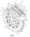
- Fig. 1 is a perspective view of a disc brake according to the invention
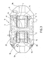
- Fig. 2 is a perspective view of a detail of the disc brake as shown in Fig. 1 ;
- Fig. 3 is a top view of the detail from Fig. 2 ;
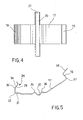
- Fig. 4 is a top view of a pad spring according to an embodiment of the invention.
- Fig. 5 is a side view of the pad spring as shown in Fig. 4 .
- Fig. 6 and 7 are two perspective views of the pad spring as shown in Fig. 4 in a rest configuration.
- Fig. 8 and 9 are two perspective views of the pad spring as shown in Fig. 4 in a deformed working configuration.
- a disc brake particularly to be used in motor vehicles, is generally designated with numeral 1.
- it is a disc brake with stationary caliper.
- the disc brake 1 comprises a caliper 2 and a disc brake 39.
- the caliper 2 can be secured, by means of clamping screws, to a vehicle suspension, whereas the brake disc 39, provided with a circular braking band 4, can be connected to the wheel hub of the vehicle.
- the caliper 2 comprises two side walls 3 arranged on both sides of the disc brake 39 and connected to each other by means of connecting elements extending astride the braking band 4.
- the caliper 2 comprises two end bridges 9a, 9b defining a middle aperture 10, as well as a tie-rod 11, arranged in said middle aperture 10 structurally connecting the two side walls 3 such as to restrain the deformation of the caliper 2 while braking.
- the tie-rod 11 is arranged approximatively in the center of the middle aperture 10 such that the latter is divided in two half-apertures 12, 13, having substantially the same circumferential extension (relative to the brake disc).
- the support pins 15 have such size and mechanical strength that the pads can be hung to these support pins, such as by means of a hole or slot 16 drilled in the plate 6 at an upper edge 23 thereof, in order to prevent the pads 5 from radially shifting (relative to the rotation axis of the disc brake).
- the support pins 15 for the pads do not contribute to the overall rigidity of the caliper 2.
- the pads 5, that can be moved in the perpendicular direction to the brake disc 39, can be affected by thrust means, such as one or more hydraulic cylinder-piston assemblies (not shown in the figures), which are arranged within the caliper 2, such that a sector of the braking band 4, the shape and surface thereof mating the friction coatings 7, is tightened by means of the friction coating 7.
- thrust means such as one or more hydraulic cylinder-piston assemblies (not shown in the figures), which are arranged within the caliper 2, such that a sector of the braking band 4, the shape and surface thereof mating the friction coatings 7, is tightened by means of the friction coating 7.
- At least a suitable pad spring 14 is provided to apply an elastic preload on the pads 5 such that the latter are stopped within the seats 8 even when the brake is deactivated, thereby the vibrations and noise of the brake due to the movements of the pads are also reduced.
- the spring 14 comprises a longitudinal beam 17 with two ends 18, 19 suitable to engage counter-portions, either integral with or connected to the caliper, and a cross beam 20 connected to the cross beam 17 and oriented in a transversal direction, preferably substantially perpendicular to the longitudinal direction of the longitudinal beam 17.
- the cross beam 20 has two ends 21, 22 suitable to engage the upper edge 23 of the plates 6 of the pads 5 such that the latter are elastically held in position.
- the spring 14 forms a seat 24 for snap attachment of the longitudinal beam 17 to one of the counter portions integral with the caliper 2.
- the snap attachment seat 24 is formed at the first end 18 of the longitudinal beam 17 and has such as a shape as to allow a snap engagement, preferably with the tie-rod 11 structurally connecting the two side walls 3 of the caliper.
- the second end 19 of the longitudinal beam 17 is arranged opposite the snap attachment seat 24 and forms an abutment seat against one of the two support pins 15 to which the pad plates 6 are attached.
- the spring 14 is formed as one piece, preferably in a plate-like or belt-like material shaped such as to have only curvatures about axes substantially parallel and substantially perpendicular to the plane of the brake disc when the spring is assembled in the caliper.
- the tie-rod 11 and the snap attachment seat 24 of the spring 14 are arranged and shaped such that, upon an elastic deformation of the spring 14 as required to bring the second end 22 thereof into pressing abutment against the support pin 15, the spring 14 is left attached to the tie-rod 11.
- the tie-rod 11 has an at least partially polygonal shape in cross-section.
- the tie-rod 11 forms a stop surface 25 substantially planar and facing outward from the caliper, or in other words, facing away from the pads, with an adjacent edge 26 defining the side of the stop surface 25 closer to the pads and a counter-surface 27 facing an approximatively opposite direction relative to the stop surface 25 and defined by an adjacent edge 28.
- the snap attachment seat 24 of the spring also has a sectional at least partially polygonal shape, and particularly a stop tract 29 substantially planar and complementary with the stop surface 25, in which the stop tract 29 is defined by a substantially straight fold 30 forming an inner angle suitable to accommodate the edge 26 of the tie-rod 11.
- the snap fit seat 24 also forms a counter tract 31 which is substantially planar and complementary with the counter surface 27, in which the counter tract 31 is defined by a substantially straight fold 32 forming an inner angle suitable to house the edge 28 of the tie-rod 11.
- the distance between the stop tract 29 and the counter tract 31 of the snap attachment seat 24 is slightly shorter than the corresponding distance between the stop surface 25 and the counter surface 27 of the tie-rod 11, such that, due to the elastic deformability of the seat 24, this is connected to the tie-rod 11 by means of interference.
- the further mutual engagement of the straight folds 30, 32 of the seat 24 with the corresponding edges 26, 28 of the tie-rod greatly increase the effectiveness of the snap engagement, without having to resort to high elastic preload of the spring.
- the tie-rod can form appropriate grooves or projections suitable to improve the engagement with the seat 24 of the spring 14.
- the two support pins 15 are preferably arranged each at one of the half-apertures 12 and 13, preferably proximate to one of the end bridges 9a, 9b of the caliper, respectively. Since the support pins 15 pass through the holes 16 of the pads, they require to be removably fixed to the caliper. To removably fix the two support pins 15, suitable seats 33 are provided, for example threaded holes formed in outer edges 34 opposite to each other of the two side walls 3 of the caliper.
- the quick-snap attachment seat 24 engages by means of pressing contact the side of the tie-rod 11 facing the pads 5 and the second end 19 of the longitudinal beam 17 engages by means of pressing contact the side of one of the two support pins 15 facing the pads 5, whereas the ends 21, 22 of the cross beam 20 engage those upper edges 23 of the plates 6 of the pads 5 substantially facing outward from the caliper, or in other words, facing the tie-rod 11. In this manner, the pads 5 are elastically pushed away from the tie-rod 11.
- the plates 6 of the pads 5 define seats 35 suitable to house the ends 21, 22 of the cross beam 20 such that a movement of the spring 14 relative to the pads 5 is prevented or hindered in the longitudinal direction of the longitudinal beam 17, and vice versa.
- These seats 35 can either comprise cavities formed in the upper edge 23 of the plate 6 and suitable to provide a shape coupling or tracts of the upper edge 23 provided with a surface roughness suitable to provide a frictional coupling to the ends 21, 22 of the cross beam 20 of the spring.
- the cross beam 20 is connected to the longitudinal beam 17 without any sectional variation of the cross beam 20 in the area where it overlaps to the longitudinal beam and, preferably, the cross beam has a uniform sectional shape all along the entire length thereof.
- the cross beam 20 has a C-shaped section, in which the convex side of the C-shaped profile faces the pads and abuts against the seats 35.
- the longitudinal beam 17 forms two further C-shaped portions 36, the convex side thereof facing away from the pads, and which extend to the area in which the longitudinal beam and the cross beam overlap along both sides of the latter, such that each C-shaped portion 36, together with the cross beam 20, have a substantially S-shaped section.
- This particular shape of the spring 14 gives high rigidity to the cross beam 20.
- the support pin 15 with which the second end 19 of the longitudinal beam is engaged has a section of substantially circular shape and, in order to obtain an effective engagement of the spring 14 with this support pin 15, the second end 19 of the longitudinal beam preferably forms a seat 37, either shaped like an arc of a circle or C-shaped, with the concave side facing the pin, or in other words, facing away from the pads.
- an actuating portion 38 preferably substantially planar, which is the free end of the second end 19 of the longitudinal beam and allows the spring 14 to be easily bent by hand upon assembly, such as described below.
- the operator mounting the brake can use a particularly long lever arm to deform the spring upon assembly.
- the cross beam 20 is arranged between said snap attachment seat 24 and the second end 19 of the longitudinal beam 17 and the distance between the cross beam and the snap attachment seat is lower than the distance between the cross beam and said second end 19. This allows the second end 19 to be easily bent when the spring is being assembled, as well as a relatively rigid abutment or fitting of the spring between the tie-rod 11 of the caliper and the pads 5 when the spring is assembled.
- the tie-rod 11 is formed as one piece with the two side walls 3 of the caliper 2, such as the whole caliper 2 including the tie-rod 11 can be made of aluminium or aluminium alloy, and thus a very light caliper is obtained, the rigidity being equal.
- the tie-rod 11 for example made of steel, is connected by means of threaded means with at least one of the two side walls of the caliper.
- the pads 5 are positioned within their seats 8 and the first support pin is inserted within the slots 16 of the plates 6 of the pads and fixed in an unlosable manner within the respective seats 33 of the caliper. Thereby, the pads are hung to one of the two support pins and cannot fall therefrom.
- the spring longitudinal beam can be now fitted to the tie-rod and rested on the upper edge of the pads by means of the cross beam. Without having to hold manually the thus defined spring position, the actuating portion 38 is pushed towards the pads until the C-shaped seat 37 of the second end of the longitudinal beam is positioned at the second support pin.
- this second support pin can be now easily inserted within the suitable slot 16 of the plate 6 of the pad and fixed within the respective seats 33 formed within the caliper 2.
- the C-shaped seat of the spring 14 engages the support pin 15 from below, thereby providing the desired elastic preload between the caliper and the pads.
- the spring 14 according to the present invention by being suitable to be attached to the tie-rod 11, can have half the size of the prior art springs.
- the spring can be mounted "unilaterally", such that the spring only extends at one half-aperture, thereby leading to a reduction in the material required for the spring and an increase in the actual cooling surface of the caliper, the rigidity of the spring being equal.
- the circumferential thrust direction of the spring 14 against the pads can further be adjusted.
Landscapes
- Engineering & Computer Science (AREA)
- General Engineering & Computer Science (AREA)
- Mechanical Engineering (AREA)
- Braking Arrangements (AREA)
- Springs (AREA)
Claims (25)
- Feder (14) für Bremsklötze (5) in einem Bremssattel (2) für eine Scheibenbremse (1), wobei die Feder (14)- einen Längsträger (17), der zwei zum Eingriff mit Gegenabschnitten (15, 11), die mit dem Bremssattel (2) verbunden sind, geeignete Enden (18, 19) aufweist,- einen Querträger (20), der mit dem Längsträger (17) verbunden ist und zwei zum Eingriff mit den Bremsklötzen (5) für ein elastisches Halten derselben geeignete Enden (21, 22),umfasst,
dadurch gekennzeichnet, dass sie einen Abschnitt umfasst, der einen Sitz (24) für die Schnappbefestigung des Längsträgers (17) an einem der Gegenabschnitte (11) bildet. - Feder (14) gemäß Anspruch 1, wobei der Schnappbefestigungssitz (24) an einem (18) der Enden (18, 19) des Längsträgers (17) ausgebildet ist und zum einschnappenden Eingriff mit einer Zugstange (11), die zwei Seitenwände (3) des Bremssattels (2) baulich verbindet, geeignet ist.
- Feder (14) gemäß Anspruch 2, wobei das Ende (19) des Längsträgers (17), das entgegengesetzt zu dem Schnappbefestigungssitz (24) angeordnet ist, einen Anlagesitz (37) für die Feder (14) gegen einen Stützbolzen (15) bildet, der die Bremsklötze (5) abstützt.
- Feder (14) gemäß einem der vorangehenden Ansprüche, die einstückig aus einem plattenförmigen Metallwerkstoff gebildet ist.
- Feder (14) gemäß Anspruch 4, wobei der plattenförmige Metallwerkstoff derart geformt ist, dass er nur Krümmungen um Achsen aufweist, die im Wesentlichen parallel zueinander und im Wesentlichen rechtwinklig zu der Ebene der Bremsscheibe (39) angeordnet sind, wenn die Feder (14) in dem Bremssattel (2) montiert ist.
- Feder (14) gemäß einem der vorangehenden Ansprüche, wobei der Querträger (20) mit dem Längsträger (17) ohne irgend eine Veränderung im Querschnitt des Querträgers (20) in dem Bereich, in dem er den Längsträger (17) überlappt, verbunden ist.
- Feder (14) gemäß einem der vorangehenden Ansprüche, wobei der Querträger (20) einen C-förmigen Querschnitt aufweist und der Längsträger (17) zwei weitere C-förmige Abschnitte (36) bildet, die sich entlang beider Seiten des Querträgers (20) derart erstrecken, dass jeder C-förmige Abschnitt (36) des Längsträgers zusammen mit dem Querträger (20) einen im Wesentlichen S-förmigen Abschnitt bildet.
- Feder (14) gemäß einem der vorangehenden Ansprüche, wobei der Längsträger (17) der Feder einen Betätigungsabschnitt (38) bildet, der derart angeordnet ist, dass er das freie Ende des zweiten Endes (19) des Längsträgers (17) bildet.
- Feder (14) gemäß einem der vorangehenden Ansprüche, wobei der Querträger (20) zwischen dem Schnappbefestigungssitz (24) und dem zweiten Ende (19) des Längsträgers (17) angeordnet ist und der Abstand zwischen dem Querträger (20) und dem Schnappbefestigungssitz (24) kürzer ist als der Abstand zwischen dem Querträger (20) und dem zweiten Ende (19).
- Eine Scheibenbremse (1) umfassend- einen Bremssattel (2) mit zwei Seitenwänden (3), die an beiden Seiten einer Scheibenebene (39) angeordnet sind und Sitze für Bremsklötze (8) bilden, wobei die zwei Seitenwände (3) mittels Endbrücken (9a, 9b), die eine mittlere Öffnung (10) bilden, miteinander verbunden sind,- eine Zugstange (11), die innerhalb der mittleren Öffnung (10) angeordnet ist und die zwei Seitenwände (3) derart baulich verbindet, dass die Verformung des Bremssattels (2) während des Bremsens verhindert wird,- wenigstens einen Stützbolzen (15), der zum Abstützen der Bremsklötze (5) geeignet ist,- zwei ein Paar bildende Bremsklötze (5), die in den Sitzen für die Bremsklötze (8) angeordnet sind und durch den Stützbolzen (15) abgestützt werden,- eine Feder (14) zum Halten der Bremsklötze (5),wobei die Feder (14)- einen Längsträger (17), der ein erstes Ende (18), das einen Sitz (24) für die Schnappbefestigung des Längsträgers (17) an der Zugstange (11) bildet, und ein zweites Ende (19) aufweist, das für den Eingriff mit dem Stützbolzen (15) geeignet ist,- einen Querträger (20), der mit dem Längsträger (17) verbunden ist und zwei entgegen gesetzte Enden (21, 22) aufweist, die für den Eingriff mit den Bremsklötzen (5) für das elastische Halten derselben geeignet ist,umfasst.
- Scheibenbremse (1) gemäß Anspruch 10, wobei die Zugstange (11) und der Schnappbefestigungssitz (24) der Feder (14) derart angeordnet und ausgebildet sind, dass die Feder (14) nach ihrer elastischen Verformung, die notwendig ist, um das zweite Ende (19) in eine Druckanlage gegen den Stützbolzen (15) zu bringen, mit der Zugstange (11) verbunden bleibt.
- Scheibenbremse (1) gemäß Anspruch 10 oder 11, wobei die Feder (14) einstückig aus einem plattenförmigen Metallwerkstoff gebildet ist.
- Scheibenbremse (1) gemäß Anspruch 12, wobei der plattenförmige Metallwerkstoff derart geformt ist, dass er dann, wenn die Feder (14) in dem Bremssattel (2) montiert ist, nur Krümmungen um Achsen aufweist, die im Wesentlichen parallel zueinander und im Wesentlichen rechtwinklig zu der Ebene der Bremsscheibe verlaufen.
- Scheibenbremse (1) gemäß Anspruch 10 oder einem seiner Unteransprüche, wobei die Zugstange (11) einstückig mit den zwei Seitenwänden (3) des Bremssattels (2) ausgebildet ist.
- Scheibenbremse (1) gemäß Anspruch 14, wobei die Zugstange (11) und die zwei Seitenwände (3) aus Aluminium oder einer Aluminiumlegierung hergestellt sind.
- Scheibenbremse (1) gemäß Anspruch 10 oder einem seiner Unteransprüche, wobei die Zugstange (11) mittels Gewindemittel mit wenigstens einer der zwei Seitenwände (3) des Bremssattels (2) verbunden ist.
- Scheibenbremse (1) gemäß Anspruch 16, wobei die Zugstange (11) aus Stahl hergestellt ist.
- Scheibenbremse (1) gemäß Anspruch 10 oder einem seiner Unteransprüche, wobei- der Schnappbefestigungssitz (24) mit der Seite der Zugstange (11), die den Bremsklötzen (5) zugewandt ist, in Druckkontakt Eingriff ist,- das zweite Ende (19) des Längsträgers (17) durch den Druckkontakt mit der Seite des Stützbolzens (15), die den Bremsklötzen (5) zugewandt ist, in Eingriff ist,- die Enden (21, 22) des Querträgers (20) mit Kanten (23) der Bremsklötze (5) in Eingriff sind, die im Wesentlichen der Zugstange (11) derart zugewandt sind, dass die Bremsklötze (5) von der Zugstange (11) elastisch weggedrückt werden.
- Scheibenbremse (1) gemäß Anspruch 10 oder einem seiner Unteransprüche, wobei die Bremsklötze (5) Sitze (35) bilden, die zur derartigen Aufnahme des Querträgers (20) geeignet sind, dass eine Bewegung der Feder (14) relativ zu den Bremsklötzen (50) in Längsrichtung des Längsträgers (17) verhindert oder erschwert ist.
- Scheibenbremse (1) gemäß Anspruch 10 oder einem seiner Unteransprüche, wobei die Zugstange (11) einen wenigstens teilweise polygonalförmigen Querschnitt aufweist und der Schnappbefestigungssitz (24) der Feder (14) einen wenigstens teilweise polygonalförmigen Querschnitt aufweist, der zu der teilweisen Polygonalform der Zugstange (11) annähernd komplementär ausgebildet ist und eine derartig geringfügig kleinere Größe aufweist, dass eine Pressverbindung mit der Zugstange (11) bereitgestellt ist.
- Scheibenbremse (1) gemäß Anspruch 10 oder einem seiner Unteransprüche umfassend zwei Stützbolzen (15), die jeweils in der Nähe einer der Endbrücken (9a, 9b) des Bremssattels angeordnet sind und wobei die Bremsklötze durch beide Stützbolzen (15) befestigt sind.
- Scheibenbremse (1) gemäß Anspruch 10 oder einem seiner Unteransprüche, wobei der Querträger (20) mit dem Längsträger (17) ohne irgend eine Veränderung des Querschnitts des Querträgers (20) in dem Bereich, in dem er den Längsträger (17) überdeckt, verbunden ist.
- Scheibenbremse (1) gemäß Anspruch 10 oder einem seiner Unteransprüche, wobei der Querträger (20) einen C-förmigen Querschnitt aufweist und der Längsträger (17) zwei weitere C-förmige Abschnitte (36) bildet, die sich entlang beider Seiten des Querträgers (20) derart erstrecken, dass jeder C-förmige Abschnitt (36) des Längsträgers zusammen mit dem Querträger (20) einen im Wesentlichen S-förmigen Abschnitt bildet.
- Scheibenbremse (1) gemäß Anspruch 10 oder einem seiner Unteransprüche, wobei der Längsträger (17) der Feder einen Betätigungsabschnitt (38) bildet, der derart angeordnet ist, dass er das freie Ende des zweiten Endes (19) des Längsträgers (17) bildet.
- Scheibenbremse (1) gemäß Anspruch 10, wobei der Querträger (20) zwischen dem Schnappbefestigungssitz (24) und dem zweiten Ende (19) des Längsträgers (17) angeordnet ist und der Abstand zwischen dem Querträger (20) und dem Schnappbefestigungssitz (24) kürzer als der Abstand zwischen dem Querträger (20) und dem zweiten Ende (19) ist.
Applications Claiming Priority (1)
| Application Number | Priority Date | Filing Date | Title |
|---|---|---|---|
| PCT/IT2006/000082 WO2007094017A1 (en) | 2006-02-17 | 2006-02-17 | Spring for holding pads in a disc brake caliper |
Publications (2)
| Publication Number | Publication Date |
|---|---|
| EP1984643A1 EP1984643A1 (de) | 2008-10-29 |
| EP1984643B1 true EP1984643B1 (de) | 2009-07-22 |
Family
ID=37075976
Family Applications (1)
| Application Number | Title | Priority Date | Filing Date |
|---|---|---|---|
| EP06728432A Expired - Lifetime EP1984643B1 (de) | 2006-02-17 | 2006-02-17 | Federn zum halten von backen in einem scheibenbremssattel |
Country Status (4)
| Country | Link |
|---|---|
| EP (1) | EP1984643B1 (de) |
| AT (1) | ATE437313T1 (de) |
| DE (1) | DE602006008047D1 (de) |
| WO (1) | WO2007094017A1 (de) |
Cited By (2)
| Publication number | Priority date | Publication date | Assignee | Title |
|---|---|---|---|---|
| US11946519B2 (en) * | 2020-08-07 | 2024-04-02 | Akebono Brake Industry Co., Ltd. | Disc brake device |
| TWI923392B (zh) | 2020-02-12 | 2026-04-21 | 日商日立安斯泰莫股份有限公司 | 碟式煞車 |
Families Citing this family (4)
| Publication number | Priority date | Publication date | Assignee | Title |
|---|---|---|---|---|
| IT1396961B1 (it) * | 2009-12-24 | 2012-12-20 | Freni Brembo Spa | Corpo pinza di un freno a disco |
| DE102010043898A1 (de) | 2010-06-02 | 2011-12-08 | Continental Teves Ag & Co. Ohg | Festsattelbremse und Bremsbelag für eine Festsattelbremse |
| GB2548632B (en) * | 2016-03-26 | 2022-04-27 | Alcon Components Ltd | Lightweight disc brake caliper body |
| CN115956169B (zh) * | 2020-08-25 | 2025-10-03 | 本田技研工业株式会社 | 盘式制动装置 |
Family Cites Families (5)
| Publication number | Priority date | Publication date | Assignee | Title |
|---|---|---|---|---|
| US3243017A (en) * | 1964-07-02 | 1966-03-29 | Gen Motors Corp | Hydraulically operable disc brakes for motor vehicles |
| AR245274A1 (es) * | 1989-08-11 | 1993-12-30 | Lucas Ind Plc | Mejoras en un freno de disco del tipo de punto que elimina el ruido producido por el roce de las pastillas sobre el freno. |
| EP0794349B1 (de) * | 1996-03-06 | 2001-06-13 | Aisin Seiki Kabushiki Kaisha | Scheibenbremssattel |
| EP1158196A3 (de) * | 2000-05-23 | 2002-08-28 | Continental Teves AG & Co. oHG | Teilbelagscheibenbremse mit Bremsbelagabstützung |
| US6971486B2 (en) * | 2004-03-04 | 2005-12-06 | Continental Teves, Inc. | Caliper spring clip with axial force direction |
-
2006
- 2006-02-17 AT AT06728432T patent/ATE437313T1/de not_active IP Right Cessation
- 2006-02-17 DE DE602006008047T patent/DE602006008047D1/de not_active Expired - Lifetime
- 2006-02-17 EP EP06728432A patent/EP1984643B1/de not_active Expired - Lifetime
- 2006-02-17 WO PCT/IT2006/000082 patent/WO2007094017A1/en not_active Ceased
Cited By (2)
| Publication number | Priority date | Publication date | Assignee | Title |
|---|---|---|---|---|
| TWI923392B (zh) | 2020-02-12 | 2026-04-21 | 日商日立安斯泰莫股份有限公司 | 碟式煞車 |
| US11946519B2 (en) * | 2020-08-07 | 2024-04-02 | Akebono Brake Industry Co., Ltd. | Disc brake device |
Also Published As
| Publication number | Publication date |
|---|---|
| EP1984643A1 (de) | 2008-10-29 |
| WO2007094017A1 (en) | 2007-08-23 |
| DE602006008047D1 (de) | 2009-09-03 |
| ATE437313T1 (de) | 2009-08-15 |
Similar Documents
| Publication | Publication Date | Title |
|---|---|---|
| US5464077A (en) | Floating-caliper spot-type disc brake for high-powered vehicles | |
| JP4503295B2 (ja) | 改良型ディスクブレーキキャリパ | |
| US5109959A (en) | Disc brake pad assembly which resists radial outward displacement | |
| EP2604881B1 (de) | Trommelbremsartige elektrische Parkbremsvorrichtung | |
| JP4067689B2 (ja) | 対向ピストン型ディスクブレーキ | |
| JP4547090B2 (ja) | ディスク・ブレーキ・システム | |
| EP1303708B1 (de) | Bremssattel für eine festsattel-scheibenbremse | |
| US9062726B2 (en) | Disc brake device and caliper | |
| JP4698147B2 (ja) | ディスクブレーキ組立体 | |
| US20180106310A1 (en) | Disc brake device | |
| KR20040102232A (ko) | 부동 캘리퍼와 브레이크 앙카 플레이트에 직접적으로지지된 다수 개의 외부 브레이크 패드가 장치된 디스크브레이크 | |
| JP2004501321A (ja) | 車両用ディスクブレーキ | |
| US20180347648A1 (en) | Brake pad | |
| CA2586272A1 (en) | Lining support plate a disc brakes | |
| EP1984643B1 (de) | Federn zum halten von backen in einem scheibenbremssattel | |
| US4964490A (en) | Pin type disc brake | |
| EP4107405B1 (de) | Bremsbelaghaltesystem, bremsbelag und fahrzeug | |
| KR20230140524A (ko) | 브레이크 캘리퍼 및 이의 생산방법 | |
| KR101770903B1 (ko) | 디스크 브레이크 | |
| US7234568B2 (en) | High performance disk brake | |
| US11408474B2 (en) | Guide assembly for a disc brake | |
| EP1211433A2 (de) | Verfahren und Vorrichtung zur Montage einer Bremsscheibe | |
| JP7361453B2 (ja) | ディスクブレーキ | |
| US20080156595A1 (en) | Disc brake apparatus of opposed-piston type | |
| JP4718422B2 (ja) | ディスクブレーキ |
Legal Events
| Date | Code | Title | Description |
|---|---|---|---|
| PUAI | Public reference made under article 153(3) epc to a published international application that has entered the european phase |
Free format text: ORIGINAL CODE: 0009012 |
|
| 17P | Request for examination filed |
Effective date: 20080703 |
|
| AK | Designated contracting states |
Kind code of ref document: A1 Designated state(s): AT BE BG CH CY CZ DE DK EE ES FI FR GB GR HU IE IS IT LI LT LU LV MC NL PL PT RO SE SI SK TR |
|
| GRAP | Despatch of communication of intention to grant a patent |
Free format text: ORIGINAL CODE: EPIDOSNIGR1 |
|
| GRAS | Grant fee paid |
Free format text: ORIGINAL CODE: EPIDOSNIGR3 |
|
| GRAA | (expected) grant |
Free format text: ORIGINAL CODE: 0009210 |
|
| AK | Designated contracting states |
Kind code of ref document: B1 Designated state(s): AT BE BG CH CY CZ DE DK EE ES FI FR GB GR HU IE IS IT LI LT LU LV MC NL PL PT RO SE SI SK TR |
|
| REG | Reference to a national code |
Ref country code: GB Ref legal event code: FG4D |
|
| REG | Reference to a national code |
Ref country code: CH Ref legal event code: EP |
|
| REG | Reference to a national code |
Ref country code: IE Ref legal event code: FG4D |
|
| REF | Corresponds to: |
Ref document number: 602006008047 Country of ref document: DE Date of ref document: 20090903 Kind code of ref document: P |
|
| NLV1 | Nl: lapsed or annulled due to failure to fulfill the requirements of art. 29p and 29m of the patents act | ||
| PG25 | Lapsed in a contracting state [announced via postgrant information from national office to epo] |
Ref country code: LT Free format text: LAPSE BECAUSE OF FAILURE TO SUBMIT A TRANSLATION OF THE DESCRIPTION OR TO PAY THE FEE WITHIN THE PRESCRIBED TIME-LIMIT Effective date: 20090722 Ref country code: IS Free format text: LAPSE BECAUSE OF FAILURE TO SUBMIT A TRANSLATION OF THE DESCRIPTION OR TO PAY THE FEE WITHIN THE PRESCRIBED TIME-LIMIT Effective date: 20091122 Ref country code: ES Free format text: LAPSE BECAUSE OF FAILURE TO SUBMIT A TRANSLATION OF THE DESCRIPTION OR TO PAY THE FEE WITHIN THE PRESCRIBED TIME-LIMIT Effective date: 20091102 Ref country code: FI Free format text: LAPSE BECAUSE OF FAILURE TO SUBMIT A TRANSLATION OF THE DESCRIPTION OR TO PAY THE FEE WITHIN THE PRESCRIBED TIME-LIMIT Effective date: 20090722 Ref country code: AT Free format text: LAPSE BECAUSE OF FAILURE TO SUBMIT A TRANSLATION OF THE DESCRIPTION OR TO PAY THE FEE WITHIN THE PRESCRIBED TIME-LIMIT Effective date: 20090722 Ref country code: SE Free format text: LAPSE BECAUSE OF FAILURE TO SUBMIT A TRANSLATION OF THE DESCRIPTION OR TO PAY THE FEE WITHIN THE PRESCRIBED TIME-LIMIT Effective date: 20090722 |
|
| PG25 | Lapsed in a contracting state [announced via postgrant information from national office to epo] |
Ref country code: PL Free format text: LAPSE BECAUSE OF FAILURE TO SUBMIT A TRANSLATION OF THE DESCRIPTION OR TO PAY THE FEE WITHIN THE PRESCRIBED TIME-LIMIT Effective date: 20090722 Ref country code: LV Free format text: LAPSE BECAUSE OF FAILURE TO SUBMIT A TRANSLATION OF THE DESCRIPTION OR TO PAY THE FEE WITHIN THE PRESCRIBED TIME-LIMIT Effective date: 20090722 Ref country code: SI Free format text: LAPSE BECAUSE OF FAILURE TO SUBMIT A TRANSLATION OF THE DESCRIPTION OR TO PAY THE FEE WITHIN THE PRESCRIBED TIME-LIMIT Effective date: 20090722 Ref country code: NL Free format text: LAPSE BECAUSE OF FAILURE TO SUBMIT A TRANSLATION OF THE DESCRIPTION OR TO PAY THE FEE WITHIN THE PRESCRIBED TIME-LIMIT Effective date: 20090722 |
|
| PG25 | Lapsed in a contracting state [announced via postgrant information from national office to epo] |
Ref country code: PT Free format text: LAPSE BECAUSE OF FAILURE TO SUBMIT A TRANSLATION OF THE DESCRIPTION OR TO PAY THE FEE WITHIN THE PRESCRIBED TIME-LIMIT Effective date: 20091122 Ref country code: BG Free format text: LAPSE BECAUSE OF FAILURE TO SUBMIT A TRANSLATION OF THE DESCRIPTION OR TO PAY THE FEE WITHIN THE PRESCRIBED TIME-LIMIT Effective date: 20091022 |
|
| PG25 | Lapsed in a contracting state [announced via postgrant information from national office to epo] |
Ref country code: DK Free format text: LAPSE BECAUSE OF FAILURE TO SUBMIT A TRANSLATION OF THE DESCRIPTION OR TO PAY THE FEE WITHIN THE PRESCRIBED TIME-LIMIT Effective date: 20090722 Ref country code: CZ Free format text: LAPSE BECAUSE OF FAILURE TO SUBMIT A TRANSLATION OF THE DESCRIPTION OR TO PAY THE FEE WITHIN THE PRESCRIBED TIME-LIMIT Effective date: 20090722 Ref country code: RO Free format text: LAPSE BECAUSE OF FAILURE TO SUBMIT A TRANSLATION OF THE DESCRIPTION OR TO PAY THE FEE WITHIN THE PRESCRIBED TIME-LIMIT Effective date: 20090722 Ref country code: EE Free format text: LAPSE BECAUSE OF FAILURE TO SUBMIT A TRANSLATION OF THE DESCRIPTION OR TO PAY THE FEE WITHIN THE PRESCRIBED TIME-LIMIT Effective date: 20090722 |
|
| PLBE | No opposition filed within time limit |
Free format text: ORIGINAL CODE: 0009261 |
|
| STAA | Information on the status of an ep patent application or granted ep patent |
Free format text: STATUS: NO OPPOSITION FILED WITHIN TIME LIMIT |
|
| PG25 | Lapsed in a contracting state [announced via postgrant information from national office to epo] |
Ref country code: BE Free format text: LAPSE BECAUSE OF FAILURE TO SUBMIT A TRANSLATION OF THE DESCRIPTION OR TO PAY THE FEE WITHIN THE PRESCRIBED TIME-LIMIT Effective date: 20090722 Ref country code: SK Free format text: LAPSE BECAUSE OF FAILURE TO SUBMIT A TRANSLATION OF THE DESCRIPTION OR TO PAY THE FEE WITHIN THE PRESCRIBED TIME-LIMIT Effective date: 20090722 |
|
| 26N | No opposition filed |
Effective date: 20100423 |
|
| REG | Reference to a national code |
Ref country code: CH Ref legal event code: PL |
|
| PG25 | Lapsed in a contracting state [announced via postgrant information from national office to epo] |
Ref country code: MC Free format text: LAPSE BECAUSE OF NON-PAYMENT OF DUE FEES Effective date: 20100301 Ref country code: LI Free format text: LAPSE BECAUSE OF NON-PAYMENT OF DUE FEES Effective date: 20100228 Ref country code: GR Free format text: LAPSE BECAUSE OF FAILURE TO SUBMIT A TRANSLATION OF THE DESCRIPTION OR TO PAY THE FEE WITHIN THE PRESCRIBED TIME-LIMIT Effective date: 20091023 Ref country code: CH Free format text: LAPSE BECAUSE OF NON-PAYMENT OF DUE FEES Effective date: 20100228 |
|
| REG | Reference to a national code |
Ref country code: FR Ref legal event code: ST Effective date: 20101029 |
|
| PG25 | Lapsed in a contracting state [announced via postgrant information from national office to epo] |
Ref country code: IE Free format text: LAPSE BECAUSE OF NON-PAYMENT OF DUE FEES Effective date: 20100217 Ref country code: FR Free format text: LAPSE BECAUSE OF NON-PAYMENT OF DUE FEES Effective date: 20100301 |
|
| PGFP | Annual fee paid to national office [announced via postgrant information from national office to epo] |
Ref country code: GB Payment date: 20120221 Year of fee payment: 7 |
|
| PG25 | Lapsed in a contracting state [announced via postgrant information from national office to epo] |
Ref country code: CY Free format text: LAPSE BECAUSE OF FAILURE TO SUBMIT A TRANSLATION OF THE DESCRIPTION OR TO PAY THE FEE WITHIN THE PRESCRIBED TIME-LIMIT Effective date: 20090722 |
|
| PG25 | Lapsed in a contracting state [announced via postgrant information from national office to epo] |
Ref country code: LU Free format text: LAPSE BECAUSE OF NON-PAYMENT OF DUE FEES Effective date: 20100217 Ref country code: HU Free format text: LAPSE BECAUSE OF FAILURE TO SUBMIT A TRANSLATION OF THE DESCRIPTION OR TO PAY THE FEE WITHIN THE PRESCRIBED TIME-LIMIT Effective date: 20100123 |
|
| PG25 | Lapsed in a contracting state [announced via postgrant information from national office to epo] |
Ref country code: TR Free format text: LAPSE BECAUSE OF FAILURE TO SUBMIT A TRANSLATION OF THE DESCRIPTION OR TO PAY THE FEE WITHIN THE PRESCRIBED TIME-LIMIT Effective date: 20090722 |
|
| GBPC | Gb: european patent ceased through non-payment of renewal fee |
Effective date: 20130217 |
|
| PG25 | Lapsed in a contracting state [announced via postgrant information from national office to epo] |
Ref country code: GB Free format text: LAPSE BECAUSE OF NON-PAYMENT OF DUE FEES Effective date: 20130217 |
|
| PGFP | Annual fee paid to national office [announced via postgrant information from national office to epo] |
Ref country code: DE Payment date: 20170428 Year of fee payment: 12 |
|
| REG | Reference to a national code |
Ref country code: DE Ref legal event code: R119 Ref document number: 602006008047 Country of ref document: DE |
|
| PG25 | Lapsed in a contracting state [announced via postgrant information from national office to epo] |
Ref country code: DE Free format text: LAPSE BECAUSE OF NON-PAYMENT OF DUE FEES Effective date: 20180901 |
|
| P01 | Opt-out of the competence of the unified patent court (upc) registered |
Effective date: 20230526 |
|
| PGFP | Annual fee paid to national office [announced via postgrant information from national office to epo] |
Ref country code: IT Payment date: 20250120 Year of fee payment: 20 |