EP1984682B1 - Eiserzeugungsvorrichtung für einen kühlschrank und kühlschrank damit - Google Patents
Eiserzeugungsvorrichtung für einen kühlschrank und kühlschrank damit Download PDFInfo
- Publication number
- EP1984682B1 EP1984682B1 EP06835257.4A EP06835257A EP1984682B1 EP 1984682 B1 EP1984682 B1 EP 1984682B1 EP 06835257 A EP06835257 A EP 06835257A EP 1984682 B1 EP1984682 B1 EP 1984682B1
- Authority
- EP
- European Patent Office
- Prior art keywords
- ice
- guide
- tray
- water tank
- water
- Prior art date
- Legal status (The legal status is an assumption and is not a legal conclusion. Google has not performed a legal analysis and makes no representation as to the accuracy of the status listed.)
- Active
Links
Images









Classifications
-
- F—MECHANICAL ENGINEERING; LIGHTING; HEATING; WEAPONS; BLASTING
- F25—REFRIGERATION OR COOLING; COMBINED HEATING AND REFRIGERATION SYSTEMS; HEAT PUMP SYSTEMS; MANUFACTURE OR STORAGE OF ICE; LIQUEFACTION SOLIDIFICATION OF GASES
- F25C—PRODUCING, WORKING OR HANDLING ICE
- F25C1/00—Producing ice
- F25C1/04—Producing ice by using stationary moulds
-
- F—MECHANICAL ENGINEERING; LIGHTING; HEATING; WEAPONS; BLASTING
- F25—REFRIGERATION OR COOLING; COMBINED HEATING AND REFRIGERATION SYSTEMS; HEAT PUMP SYSTEMS; MANUFACTURE OR STORAGE OF ICE; LIQUEFACTION SOLIDIFICATION OF GASES
- F25C—PRODUCING, WORKING OR HANDLING ICE
- F25C1/00—Producing ice
- F25C1/22—Construction of moulds; Filling devices for moulds
- F25C1/25—Filling devices for moulds
-
- F—MECHANICAL ENGINEERING; LIGHTING; HEATING; WEAPONS; BLASTING
- F25—REFRIGERATION OR COOLING; COMBINED HEATING AND REFRIGERATION SYSTEMS; HEAT PUMP SYSTEMS; MANUFACTURE OR STORAGE OF ICE; LIQUEFACTION SOLIDIFICATION OF GASES
- F25C—PRODUCING, WORKING OR HANDLING ICE
- F25C5/00—Working or handling ice
- F25C5/20—Distributing ice
- F25C5/22—Distributing ice particularly adapted for household refrigerators
-
- F—MECHANICAL ENGINEERING; LIGHTING; HEATING; WEAPONS; BLASTING
- F25—REFRIGERATION OR COOLING; COMBINED HEATING AND REFRIGERATION SYSTEMS; HEAT PUMP SYSTEMS; MANUFACTURE OR STORAGE OF ICE; LIQUEFACTION SOLIDIFICATION OF GASES
- F25C—PRODUCING, WORKING OR HANDLING ICE
- F25C2400/00—Auxiliary features or devices for producing, working or handling ice
- F25C2400/06—Multiple ice moulds or trays therefor
-
- F—MECHANICAL ENGINEERING; LIGHTING; HEATING; WEAPONS; BLASTING
- F25—REFRIGERATION OR COOLING; COMBINED HEATING AND REFRIGERATION SYSTEMS; HEAT PUMP SYSTEMS; MANUFACTURE OR STORAGE OF ICE; LIQUEFACTION SOLIDIFICATION OF GASES
- F25C—PRODUCING, WORKING OR HANDLING ICE
- F25C2400/00—Auxiliary features or devices for producing, working or handling ice
- F25C2400/10—Refrigerator units
-
- F—MECHANICAL ENGINEERING; LIGHTING; HEATING; WEAPONS; BLASTING
- F25—REFRIGERATION OR COOLING; COMBINED HEATING AND REFRIGERATION SYSTEMS; HEAT PUMP SYSTEMS; MANUFACTURE OR STORAGE OF ICE; LIQUEFACTION SOLIDIFICATION OF GASES
- F25C—PRODUCING, WORKING OR HANDLING ICE
- F25C2400/00—Auxiliary features or devices for producing, working or handling ice
- F25C2400/14—Water supply
-
- F—MECHANICAL ENGINEERING; LIGHTING; HEATING; WEAPONS; BLASTING
- F25—REFRIGERATION OR COOLING; COMBINED HEATING AND REFRIGERATION SYSTEMS; HEAT PUMP SYSTEMS; MANUFACTURE OR STORAGE OF ICE; LIQUEFACTION SOLIDIFICATION OF GASES
- F25D—REFRIGERATORS; COLD ROOMS; ICE-BOXES; COOLING OR FREEZING APPARATUS NOT OTHERWISE PROVIDED FOR
- F25D23/00—General constructional features
- F25D23/02—Doors; Covers
- F25D23/04—Doors; Covers with special compartments, e.g. butter conditioners
-
- F—MECHANICAL ENGINEERING; LIGHTING; HEATING; WEAPONS; BLASTING
- F25—REFRIGERATION OR COOLING; COMBINED HEATING AND REFRIGERATION SYSTEMS; HEAT PUMP SYSTEMS; MANUFACTURE OR STORAGE OF ICE; LIQUEFACTION SOLIDIFICATION OF GASES
- F25D—REFRIGERATORS; COLD ROOMS; ICE-BOXES; COOLING OR FREEZING APPARATUS NOT OTHERWISE PROVIDED FOR
- F25D2317/00—Details or arrangements for circulating cooling fluids; Details or arrangements for circulating gas, e.g. air, within refrigerated spaces, not provided for in other groups of this subclass
- F25D2317/06—Details or arrangements for circulating cooling fluids; Details or arrangements for circulating gas, e.g. air, within refrigerated spaces, not provided for in other groups of this subclass with forced air circulation
- F25D2317/061—Details or arrangements for circulating cooling fluids; Details or arrangements for circulating gas, e.g. air, within refrigerated spaces, not provided for in other groups of this subclass with forced air circulation through special compartments
-
- F—MECHANICAL ENGINEERING; LIGHTING; HEATING; WEAPONS; BLASTING
- F25—REFRIGERATION OR COOLING; COMBINED HEATING AND REFRIGERATION SYSTEMS; HEAT PUMP SYSTEMS; MANUFACTURE OR STORAGE OF ICE; LIQUEFACTION SOLIDIFICATION OF GASES
- F25D—REFRIGERATORS; COLD ROOMS; ICE-BOXES; COOLING OR FREEZING APPARATUS NOT OTHERWISE PROVIDED FOR
- F25D2323/00—General constructional features not provided for in other groups of this subclass
- F25D2323/02—Details of doors or covers not otherwise covered
- F25D2323/023—Door in door constructions
-
- F—MECHANICAL ENGINEERING; LIGHTING; HEATING; WEAPONS; BLASTING
- F25—REFRIGERATION OR COOLING; COMBINED HEATING AND REFRIGERATION SYSTEMS; HEAT PUMP SYSTEMS; MANUFACTURE OR STORAGE OF ICE; LIQUEFACTION SOLIDIFICATION OF GASES
- F25D—REFRIGERATORS; COLD ROOMS; ICE-BOXES; COOLING OR FREEZING APPARATUS NOT OTHERWISE PROVIDED FOR
- F25D2323/00—General constructional features not provided for in other groups of this subclass
- F25D2323/122—General constructional features not provided for in other groups of this subclass the refrigerator is characterised by a water tank for the water/ice dispenser
Definitions
- the present invention relates to a refrigerator, and more particularly, to an ice-making device for a refrigerator and a refrigerator including the ice-making device.
- Refrigerators are household appliances for keeping foods refrigerated or frozen to store the foods in a fresh state for a long time.
- the interior of the refrigerator is partitioned into freezing and refrigerating chambers, and an ice-making device is provided in the freezing chamber.
- FIGS. 1 and 2 show a refrigerator provided with a related art ice-making device
- FIG. 3 shows the ice-making device installed in the refrigerator shown in FIG. 2 .
- freezing and refrigerating chambers 11 and 13 which are partitioned side by side are provided within a main body 10 of a refrigerator.
- the main body 10 is provided with a freezing chamber door 11 a and a refrigerating chamber door 13a in order to selectively open or close the freezing and refrigerating chambers 11 and 13, respectively.
- the freezing and refrigerating chamber doors 11a and 13a are hinged to opposite lateral sides of the main body 10, respectively, such that the doors can be pivoted in a forward direction.
- home bars 15 and 17 are provided on the freezing and refrigerating chamber doors 11a and 13a, respectively. Foods such as drinking water are stored in each of the home bars 15 and 17.
- Each of the home bars 15 and 17 is composed of a home bar housing 15a or 17a and a home bar door 15b or 17b.
- the home bar housings 15a and 17a are provided on rear surfaces of the freezing and refrigerating chamber doors 11a and 13a, respectively.
- the home bar housings 15a and 17a are provided with predetermined storage spaces, respectively, in which foods such as drinking water can be received.
- Each of the home bar doors 15b and 17b serves to selectively open or close an opening that is formed by cutting out a portion of the freezing or refrigerating chamber door 11a or 13a to correspond to the home bar housing 15a or 17a.
- Each of the home bar doors 15b and 17b is installed to be vertically pivoted.
- an ice-making device 19 is installed at one side of the freezing chamber 11.
- the ice-making device 19 is used to make ice.
- the ice-making device 19 is retractably installed within the freezing chamber 11. Further, as shown in FIG. 3 , the ice-making device 19 is composed of a support frame 21 and a pair of ice trays 23.
- the support frame 21 is formed into a rectangular shape.
- the support frame 21 functions to rotatably support the ice trays 23. That is, the ice trays 23 can be installed to be rotatable within the support frame 21.
- Each of the ice trays 23 is formed with a plurality of ice-making grooves 23a.
- Support shafts 24 are provided at the centers of front and rear surfaces of the ice trays 23, respectively.
- the ice tray 23 is rotated clockwise or counterclockwise about the support shaft 24 as viewed in FIG. 2 .
- the support shaft 24 is rotatably inserted into the rear surface of the support frame 21.
- a stopper 25 is installed at a certain position on the rear surface of the support frame 21 corresponding to the left side of the support shaft 24 as viewed in this figure.
- the stopper 25 protrudes from the rear surface of the support frame 21 by a predetermined distance and is positioned on a moving path of the ice tray 23.
- the ice tray 23 rotating about the support shaft 24 is twisted by the stopper 25.
- a handle 26 is provided on a front surface of the support frame 21 corresponding to the front side of the ice tray 23.
- the handle 26 is a portion which a user grips to rotate the ice tray 23.
- a pair of handles 26 are provided to be in harmony with the number of ice trays 23.
- an ice bank 27 is installed below the ice-making device 19 within the freezing chamber 11. Ice made in the ice-making device 19 is stored in the ice bank 27. The ice bank 27 is also retractably installed within the freezing chamber 11.
- the ice-making device configured as such is operated as follows.
- the ice-making grooves 23a of the ice tray 23 are filled with water.
- the freezing chamber door 11a is opened to open the freezing chamber 11.
- the ice-making device 19 is received at one side of the freezing chamber 11. After the ice-making device 19 is installed in such a way, the freezing chamber door 11a is closed to close the freezing chamber 11.
- the freezing chamber door 11 a is again opened to open the freezing chamber 11. If the handle 26 is rotated clockwise as viewed in FIG. 2 , the ice tray 23 is also rotated in the same direction.
- the ice tray 23 When the ice tray 23 is rotated by a predetermined angle, a rear end of the ice tray 23 is caught to the stopper 25. Thus, the ice tray 23 cannot be further rotated clockwise as viewed in FIG. 2 . If the handle 26 is further rotated clockwise from such a state as viewed in FIG. 2 , the ice tray 23 is twisted. Therefore, ice made in the ice-making grooves 23a is separated from the ice tray 23 and then stored in the ice bank 27.
- the ice bank 27 is accommodated in the freezing chamber 11. Thus, it is likely that ice stored in the ice bank 27 is impregnated with odor of foods stored in the freezing chamber 11.
- WO 2005/026631 discloses an ice mold supply system for refrigeration appliances of the type comprising a freezer compartment in whose interior is provided rails for the ice mold.
- US 6,148,624 discloses an ice making system for a refrigerator having a cabinet type freezer compartment and a door or closure member on which an ice maker is mounted along with an ice bucket.
- An object of the present invention is to provide an ice-making device for a refrigerator capable of withdrawing ice in a simpler way, and a refrigerator having the same.
- Another object of the present invention is to provide an ice-making device for a refrigerator capable of minimizing power consumption when ice is taken out, and a refrigerator having the same.
- a further object of the present invention is to provide an ice-making device for a refrigerator capable of minimizing contamination in the refrigerator in the process of making ice, and a refrigerator having the same.
- a still further object of the present invention is to provide an ice-making device for a refrigerator capable of preventing ice stored in an ice bank from being impregnated with odor of other foods, and a refrigerator having the same.
- a still further object of the present invention is to provide an ice-making device for a refrigerator capable of rapidly making ice, and a refrigerator having the same.
- the present invention provides an ice-making device as set out in claim 1.
- the ice-making device for a refrigerator comprises an ice-making device for a refrigerator, comprising: a water tank detachably mounted to a rear surface of a refrigerator door; an ice-making housing detachably mounted to the rear surface of the door below the water tank and provided with a predetermined installation space therein; an ice tray mounted into the installation space and formed with a plurality of ice-making grooves in which water supplied from the water tank is frozen into ice; a valve assembly operating to selectively supply water stored in the water tank to the ice tray when the water tank is installed or withdrawn; and an ice bank for storing ice made in the ice tray, wherein the ice bank is installed in the installation space to be received in or withdrawn out of the installation space.
- the valve assembly includes: an actuating protrusion provided at a position on the rear surface of the door; a valve lever actuated by the actuating protrusion and installed to be movable through a discharge port formed in a bottom surface of the water tank to supply the water stored in the water tank to the ice tray; a valve cover provided at a tip end of the valve lever positioned in the water tank through the discharge port to selectively open or close the discharge port by movement of the valve lever; and an elastic member for imparting an elastic force to the valve lever in a direction in which the valve cover is moved to close the discharge port.
- the water tank is detachably installed in a mounting space defined between a bottom surface of one of door baskets provided on the rear surface of the door and a top surface of the ice-making housing; and the actuating protrusion is formed to extend a predetermined length on the bottom surface of the door basket or the top surface of the ice-making housing corresponding to the ceiling or bottom of the mounting space in a direction in which the water tank is received in or withdrawn out of the mounting space.
- the valve lever includes a lever main body installed below the water tank to allow a tip end thereof to be pivotally moved vertically with respect to a pivot end thereof by a predetermined angle, and a lever protrusion extending upward from the tip end of the lever main body to penetrate through the discharge port; the valve cover is integrally formed with a tip end of the lever protrusion; and the valve lever is vertically pivoted within a range from a position where the valve cover is brought into close contact with a floor surface of the water tank adjacent to the discharge port to close the discharge port to a position where the valve cover is spaced apart from the floor surface of the water tank to open the discharge port.
- the elastic member is a torsion spring for imparting an elastic force to allow the valve lever to be pivoted downward.
- the water tank includes: a tank main body formed into a polyhedral shape with an open top to define a water storage space therein and provided with a discharge port at a bottom surface thereof; a tank cover coupled to the open top of the tank main body to selectively open or close the water storage space and provided with a supply port at a predetermined position thereof to allow water to be supplied and stored in the water storage space; and a supply port cover pivotally installed to the tank cover to selectively open or close the supply port, and the water tank is formed of a transparent or translucent material to visually check an amount of water stored in the water storage space from the outside.
- the water tank is prevented from being inadvertently detached, by a fixing means, in a state where the water tank is mounted to the rear surface of the door.
- the fixing means includes: a fastening hook provided on any one of the rear surface of the door and a rear surface of the water tank; and a fastening protrusion provided on the other of the rear surface of the door or the rear surface of the water tank to be selectively and elastically fastened to the fastening hook.
- the water tank is detachably installed in a mounting space defined between a bottom surface of one of door baskets provided on the rear surface of the door and a top surface of the ice-making housing; and the fastening hook has predetermined elasticity and is provided on any one of the bottom surface of the door basket and the top surface of the ice-making housing corresponding to the ceiling or bottom of the mounting space.
- the water tank detachably installed to the rear surface of the door is guided by a guide means.
- the guide means includes: a guide rib provided on any one of the rear surface of the door and a top surface of the water tank in a direction in which the water tank is received or withdrawn; and a guide groove provided on the other of the rear surface of the door and the top surface of the water tank such that the guide rib is inserted in and slid along the guide groove in the direction in which the water tank is received or withdrawn.
- the water tank is detachably installed in a mounting space defined between a bottom surface of one of door baskets provided on the rear surface of the door and a top surface of the ice-making housing; a pair of the guide ribs are provided on the bottom surface of the door basket corresponding to the ceiling of the mounting space; and a pair of the guide grooves are formed on the top surface of the water tank.
- the ice tray is installed in the installation space to be pivotal on a pair of support shafts provided on both sides thereof and pivotally supported on inner sides of the ice-making housing.
- a tray cover installed in the installation space to selectively open or close the ice-making grooves, and the tray cover is installed to be pivotable about tip ends of hinge brackets in accordance with a pivot motion of the ice tray by means of the hinge brackets extending from both sides of an end of the tray cover to allow the tip ends of the hinge brackets to be pivotally connected to inner sides of the ice-making housing.
- the tray cover is provided with a sealing rib extending a predetermined length downward from a front end on a bottom surface of the tray cover, and a peripheral rib extending a predetermined length perpendicular to an outer surface of the sealing rib; and the ice tray is provided with a sealing groove formed by downwardly depressing an end of the ice tray corresponding to the front end of the tray cover by a predetermined depth to allow a tip end of the sealing rib to be fitted therein, and a closely contact rib extending a predetermined length upward from a side of the ice tray adjacent to the sealing groove to allow an inner surface thereof to be brought into close contact with an outer surface of the sealing rib and a tip end thereof to be brought into close contact with a bottom surface of the peripheral rib.
- the tray cover further includes: a supply port formed at a position of the tray cover to allow the water stored in the water tank to be transferred to the ice tray therethrough; a water guide surface formed at a top surface of the tray cover adjacent to the supply port to guide the water into the supply port; and a guide portion formed at a position on the top surface of the tray cover corresponding to an outer periphery of the water guide surface to guide cold air supplied into the installation space into the ice tray through the supply port as well as to prevent the water stored in the water tank from being splashed while the water is supplied into the ice-making grooves of the ice tray through the supply port.
- a height of the guide portion supply is increased in a direction in which the cold air is supplied into the installation space.
- a cold air guide is connected between facing surfaces of the hinge brackets at a predetermined inclined angle toward the ice tray to guide the cold air supplied into the installation space toward the ice tray.
- the front end of the tray cover is provided with a shock absorbing member for absorbing shock generated when one side of the tray cover pivoting in accordance with a pivot motion of the ice tray comes into contact with one side of the ice-making housing.
- the ice bank is received in or withdrawn out of the installation space through a home bar provided in the door.
- the home bar includes: a home bar housing installed on the rear surface of the door below the ice-making housing and provided with a predetermined storage space; an opening formed by cutting out a portion of the door to communicate with the storage space and the installation space; and a home bar door for selectively opening or closing the opening, and the ice bank is received in or withdrawn out of the installation space through the opening.
- a pair of guide protrusions and a pair of guide slots are provided on both outer side surfaces of the guide box and both corresponding inner side surfaces of the guide frame, respectively, whereby the guide protrusions are inserted in and slid along the guide slots when the ice bank is moved in a direction in which the ice bank is received in or withdrawn out of the installation space.
- the guide protrusions are spaced apart from each other by a predetermined distance in a direction in which the ice bank is received in or withdrawn out of the installation space; and both ends of the guide slots are spaced apart from each other by a predetermined distance corresponding to the spaced distance of the guide protrusions.
- each of the guide slots includes a first horizontal section extending a predetermined length horizontally from a position on each side surface of the guide frame in a direction in which the ice bank is withdrawn out of the installation space, an inclined section extending a predetermined length from a front end of the first horizontal section a downwardly inclined angle in the withdrawal direction of the ice bank, and a second horizontal section extending a predetermined length horizontally from a front end of the inclined section in the withdrawal direction of the ice tray.
- the ice bank is formed into a hexahedral shape with an open top and provided with an ice storage space therein
- the guide box is formed into a hexahedral shape with open top, front and back in correspondence with the ice bank.
- cooperating protrusions and cooperating ribs are provided at rear ends of both the side surfaces of the ice bank and upper ends of both the side surfaces of the guide box, respectively, whereby the cooperating protrusions come into close contact with rear ends of the cooperating ribs and push the cooperating ribs to thereby allow the guide box to move together with the ice bank when the ice bank is moved in the withdrawal direction of the ice bank.
- a catching rib is provided at a front lower end of the ice bank; cooperating brackets are provided at lower ends of both sides on an open rear surface of the guide box, respectively; and the catching rib comes into close contact with a front end of a floor surface of the guide box to push the front end of the guide box and both sides of a rear lower end of the ice bank come into close contact with the cooperating brackets, respectively, to push the cooperating brackets when the ice bank is moved in a direction in which the ice bank is received in the installation space, whereby the guide box is moved together with the ice bank.
- At least one movement preventing groove is formed on any one of a bottom surface of the ice bank and the corresponding floor surface of the guide box in a direction in which the ice bank and the guide box are moved; and at least one movement preventing rib is formed on the other of the bottom surface of the ice bank and the floor surface of the guide box in the moving direction of the ice bank and the guide box, whereby the movement preventing rib is inserted in the movement preventing groove.
- an inclined portion is formed at the rear lower end of the ice bank at a downwardly inclined angle in the withdrawal direction of the ice bank to allow the ice bank, which is withdrawn out of the installation space through the opening in a state where the ice bank is securely placed on the guide box, to be moved at an upwardly inclined angle and thus the ice bank to be detached from the guide box.
- an ice-making device for a refrigerator comprising: a water tank detachably mounted to a rear surface of a refrigerator door; an ice-making housing detachably mounted to the rear surface of the door below the water tank and provided with a predetermined installation space therein; an ice tray mounted into the installation space and formed with a plurality of ice-making grooves in which water supplied from the water tank is frozen into ice; a valve assembly operating to selectively supply water stored in the water tank to the ice tray when the water tank is installed or withdrawn; and an ice bank for storing ice made in the ice tray, the ice bank being installed in the installation space to be received in or withdrawn out of the installation space through a home bar provided on the door; a guide box installed in the installation space to be received in or withdrawn out of the installation space through the home bar in a state where the ice bank is securely placed on the guide box; and a guide frame installed in the installation space to guide the guide the guide
- the water tank includes: a tank main body formed into a polyhedral shape with at least partially open top to define a water storage space therein and provided with a discharge port at a bottom surface thereof to allow the water store in the water tank to be supplied to the ice tray though the discharge port; a tank cover coupled to the open top of the tank main body to selectively open or close the water storage space and provided with a supply port at a predetermined position thereof to allow water to be supplied and stored in the water storage space; and a supply port cover pivotally installed to the tank cover to selectively open or close the supply port, and the water tank is detachably installed in a mounting space defined between a bottom surface of one of door baskets provided on the rear surface of the door and a top surface of the ice-making housing.
- the valve assembly includes: an actuating protrusion formed to extend a predetermined length on the bottom surface of the door basket or the top surface of the ice-making housing corresponding to the ceiling or bottom of the mounting space in a direction in which the water tank is received in or withdrawn out of the mounting space; a valve lever installed below the tank main body to allow a tip end thereof to be vertically pivoted with respect to a pivot end thereof within a predetermined range of angle and actuated by the actuating protrusion; a valve cover provided at the tip end of the valve lever positioned in the water storage space through the discharge port to selectively bring a bottom surface thereof into close contact with a floor surface of the water storage space by a pivot motion of the valve lever to thereby selectively open or close the discharge port; and a torsion spring for imparting an elastic force to the valve lever in a direction in the valve cover is pivoted to close the discharge port, and the valve lever is vertically pivoted by the actuating protrusion within a range from a position where the
- a fastening hook with predetermined elasticity is provided on any one of the bottom surface of the door basket and the top surface of the ice-making housing corresponding respectively to the ceiling and bottom of the mounting space; a fastening protrusion is provided on a rear surface of the tank main body to be selectively and elastically fastened to the fastening hook; and the fastening protrusion is selectively and elastically fastened to the fastening hook when the water tank is received in or withdrawn out of the mounting space, whereby the water tank is not inadvertently detached from the mounting space.
- a pair of guide ribs are formed on the bottom surface of the door basket corresponding to the ceiling of the mounting space to extend in a direction in which the water tank is received or withdrawn; a pair of guide grooves are on the top surface of the tank main body to allow the guide ribs to be inserted in and slid along the guide grooves, respectively, in a direction the water tank is received or withdrawn; and the guide ribs are inserted in and slid along the guide grooves, respectively, when the water tank is received in or withdrawn out of the mounting space, whereby movement of the water tank is guided.
- the tray cover includes: a water guide surface formed on a top surface of the tray cover corresponding to an outer periphery of a supply port to guide the water stored in the water tank into the supply port through which the water stored in the water tank is supplied to the ice tray; a guide portion formed on the top surface of the tray cover corresponding to an outer periphery of the water guide surface to guide cold air supplied into the installation space into the ice tray through the supply port as well as to prevent the water stored in the water tank from being splashed while the water is supplied into the ice-making grooves of the ice tray through the supply port; and a shock absorbing member formed at a front end of the tray cover to absorb shock generated when one side of the tray cover pivoting in accordance with the pivot motion of the ice tray comes into contact with one side of the ice-making housing.
- the tray cover is pivotally supported by hinge brackets extending from both sides of an end of the tray cover to allow tip ends of the hinge brackets to be pivotally connected to inner sides of the ice-making housing.; and a cold air guide is connected between facing surfaces of the hinge brackets at a predetermined inclined angle toward the ice tray to guide the cold air supplied into the installation space toward the ice tray.
- a pair of guide protrusions are provided on both outer side surfaces of the guide box, respectively, to be spaced apart from each other by a predetermined distance in a direction in which the ice bank is received in or withdrawn out of the installation space; and a pair of guide slots are provided on both inner side surfaces of the guide frame, respectively, to be spaced apart from each other by a predetermined distance corresponding to the spaced distance of the guide protrusions, whereby the guide protrusions are inserted in and slid along the guide slots when the ice bank is moved in a direction in which the ice bank is received in or withdrawn out of the installation space.
- the ice bank is formed into a hexahedral shape with an open top and provided with an ice storage space, and includes cooperating protrusions protruding upward from rear ends of both side surfaces thereof and a catching rib extending downward from a front lower end thereof;
- the guide box is formed into a hexahedral shape with open top, front and back in correspondence with the ice bank, and includes cooperating ribs extending in opposite directions on upper ends of both the side surfaces thereof and cooperating brackets extending in opposite directions from lower ends of both sides on a rear surface of the guide box, respectively; and the cooperating protrusions come into close contact with rear ends of the cooperating ribs and push the cooperating ribs to thereby allow the guide box to move together with the ice bank when the ice bank is moved in a direction in which the ice bank is withdrawn, the catching rib comes into close contact with a front end of a floor surface of the guide box to push the front end of the guide box and both sides of
- ice can be withdrawn in more simple and convenient way.
- power consumption when ice is taken out can be minimized.
- ice can be made and stored in a more sanitary way.
- ice can be rapidly made.
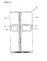
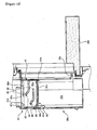
- FIGS. 4 and 5 show a refrigerator equipped with a preferred embodiment of an ice-making device for a refrigerator according to the present invention
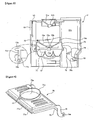
- FIG. 6 shows a mounting structure of a water tank constituting the embodiment of the present invention shown in FIG. 5
- FIG. 7 shows a valve assembly constituting the embodiment of the present invention shown in FIG. 5
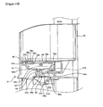
- FIG. 8 shows the interior of a first ice-making housing constituting the embodiment of the present invention shown in FIG. 5
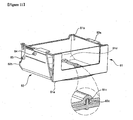
- FIG. 9 shows a tray cover constituting the embodiment of the present invention shown in FIG. 5
- FIG. 10 shows the interior of a second ice-making housing and a home bar housing constituting the embodiment of the present invention shown in FIG. 5
- FIG. 11 illustrates a state where an ice bank is securely placed on a guide box according to the embodiment of the present invention shown in FIG. 5
- FIG. 12 shows a guide frame constituting the embodiment of the present invention shown in FIG. 5 .
- freezing and refrigerating chambers 31 and 33 are provided within a main body 30 of a refrigerator.
- the freezing and refrigerating chambers 31 and 33 are partitioned side by side within the main body 30.
- freezing and refrigerating chamber doors 31a and 33a are hinged to opposite lateral sides of the main body 30, respectively, such that the doors can be horizontally pivoted.
- the freezing and refrigerating chamber doors 31a and 33a serve to selectively open or close the freezing and refrigerating chambers 31 and 33, respectively.
- support sidewalls 31b and 33b are provided at opposite side ends on rear surfaces of the freezing and refrigerating chamber doors 31a and 33a, respectively.
- Each of the support sidewalls 31b and 33b is formed in such a manner that a portion of a door liner constituting an outer appearance of the rear surface of the door 31a or 33a protrudes rearward by a predetermined height.
- a plurality of fixing protrusions are provided at corresponding positions on opposite surfaces of each of the supporting sidewalls 31b and 33b, respectively.
- a plurality of door baskets are provided on the rear surface of the freezing or refrigerating chamber door 31a or 33a between the support sidewalls 31b or 33b.
- An accommodating space for accommodating foods therein is formed in each of the door baskets.
- the door baskets are detachably installed on the rear surfaces of the freezing and refrigerating chamber doors 31a and 33a, respectively.
- a pair of fastening hooks 34a are formed at a rear end on a bottom surface of the door basket 34 provided at an uppermost portion on the rear surface of the freezing chamber door 31a.
- the fastening hooks 34a are to prevent a water tank 41 to be explained later from being inadvertently detached at a state where the water tank is mounted into a mounting space S to be explained later.
- the fastening hooks 34a extend rearward of the refrigerator door 31a, i.e. in a direction in which the water tank 41 is detached, at both sides of the rear end on the bottom surface of the door basket 34 adjacent to the rear surface of the freezing chamber door 31a.
- Each of the fastening hooks 34a has predetermined elasticity in a direction perpendicular to the mounting direction of the water tank 41.
- a pair of guide ribs 34b are formed at both ends on the bottom surface of the door basket 34 in front of the fastening hooks 34a.
- the guide ribs 34b are to guide mounting of the water tank 41.
- the guide ribs 34b are spaced apart from each other by a predetermined distance in a width direction of the freezing chamber door 31a, i.e. in a direction perpendicular to the mounting direction of the water tank 41, and extend in a thickness direction of the freezing chamber door 31a, i.e. in the mounting direction of the water tank 41.
- An actuating protrusion 34c is provided in the middle of the rear end on the bottom surface of the door basket 34.
- the actuating protrusion 34c extends rearward of the freezing chamber door 31 a, i.e. in the direction in which the water tank 41 is detached, at the middle of the rear end on the bottom surface of the door basket 34 adjacent to the rear surface of the freezing chamber door 31a, i.e. at the middle of the rear end on the bottom surface of the door basket 34 corresponding to between the fastening hooks 34a.
- the actuating protrusion 34c serves to actuate a valve lever 46 to be explained later.
- home bars 35 and 37 are provided in the freezing and refrigerating chamber doors 31a and 33a, respectively.
- the home bars 35 and 37 are used to receive or withdraw foods such as drinking water without opening the freezing and refrigerating chamber doors 31a and 33a, respectively.
- the home bar 35 or 37 comprises a home bar housing 35a or 37a and a home bar door 35b or 37b.
- the home bar housing 35a or 37a is generally formed into a polyhedral shape with the open top and front that is brought into close contact with the rear surface of the freezing or refrigerating chamber door 31a or 33a.
- the home bar housing 35a or 37a is provided on the rear surface of the freezing or refrigerating chamber door 31a or 33a corresponding to between the support sidewalls 31b or 33b.
- a storage space 35s or 37s for accommodating drinking water and the like is defined within the home bar housing 35a or 37a.
- an opening 35c or 37c is formed by cutting out a portion of the freezing or refrigerating chamber door 31a or 33a.
- the opening 35c formed in the freezing chamber door 31a communicates with the storage space 35s of the home bar housing 35a and an installation space 61s of a second ice-making housing 61 to be explained later. Through the opening 35c, therefore, food is received into or withdrawn out of the storage space 35s of the home bar housing 35a, or an ice bank 81 to be explained later is received in or withdrawn out of the installation space 61s of the second ice-making housing 61.
- the opening 37c formed in the refrigerating chamber door 33a communicates with the storage space 37s of the home bar housing 37a. Through the opening 37c, therefore, food is received into or withdrawn out of the storage space 37s of the home bar housing 37a.
- the home bar door 35b or 37b is installed on a front surface of the freezing or refrigerating chamber door 31a or 33a such that home bar door can be vertically pivoted.
- the home bar doors 35b and 37b serve to selectively open or close the openings 35c and 37c, respectively.
- the home bar door 35b installed to the freezing chamber door 31a allows the storage space 35s of the home bar housing 35a and the installation space 61s of the second ice-making housing 61 to be selectively opened or closed.
- the mounting space S is defined between the door basket 34 and the first ice-making housing 51 to be explained later. That is, the mounting space S is substantially defined between the bottom surface of the door basket 34 and a top surface of the first ice-making housing 51, which are vertically spaced apart by a predetermined distance.
- the water tank 41 is detachably installed within the mounting space S.
- the water tank 41 is filled with water which in turn will be supplied to an ice tray 71.
- a tank main body 42 of the water tank 41 is formed into a hollow polyhedral shape.
- a cover seating portion 42a is provided on a top surface of tank main body 42.
- the cover seating portion 42a is formed in such a manner that a central portion on the top surface of the tank main body 42 is stepped downward with respect to the other portions on the top surface of the tank main body 42.
- An opening 35c ( FIG. 13 ) is defined within the cover seating portion 42a.
- the opening 35c functions as an inlet through which water is stored in a water storage space 43s to be explained later.
- the cover seating portion 42a corresponding to an edge of the opening is provided with an upwardly extending insertion rib 42c ( FIG. 13 ).
- a pair of guide grooves 42d are formed on the top surface of the tank main body 42.
- Each of the guide grooves 42d extends lengthwise in the mounting direction of the water tank 41.
- the guide ribs 34b of the door basket 34 are inserted into and slid along the guide grooves 42d, respectively.
- the guide groove 42d is substantially defined by a floor surface and both side surfaces of the cover seating portion 42a and both side surfaces of a tank cover 48 to be explained later.
- fastening protrusions 42e are provided at both ends on a rear surface of tank main body 42 corresponding to the rear surface of the freezing chamber door 31a, respectively.
- the fastening protrusions 42e are elastically fastened to the fastening hooks 34a of the door basket 34 in a state where the water tank 41 is mounted into the mounting space S.
- a water storing portion 43 is defined within the tank main body 42.
- the water storing portion 43 is formed with the water storage space 43s in which a predetermined amount of water (i.e., an amount of water required for making ice one time in the ice tray 71) is stored.
- the water storing portion 43 is formed into a hopper shape extending downward from the edge of the opening 35c.
- the insertion rib 42c and the water storing portion 43 are integrally formed with the tank main body 42. The shapes of the insertion rib 42c and the water storing portion 43 are shown in more detail in FIG. 13 .
- At least a portion of the tank main body 42 (and/or the tank cover 48, a supply port cover 49) be formed of a transparent or translucent material. The reason is that a user can check an amount of water stored in the water storage space 43s from the outside.
- a discharge port 43h is provided at the central bottom of the water storage portion 43. Water stored in the water storage space 43s is supplied to the ice tray 71 through the discharge port 43h of the water tank 41.
- the discharge port 43h of the water tank 41 is preferably positioned above a guiding inclined portion 51a of the first ice-making housing 51 when the water tank 41 is mounted into the mounting space S.
- a valve guide 44 is provided on a bottom surface of the water storing portion 43 corresponding to an outer periphery of the discharge port 43h of the water tank 41.
- the valve guide 44 serves to guide movement of a valve protrusion 46b to be explained later.
- the valve guide 44 is generally formed into a cylindrical shape. Further, a cutout 44a is formed at one side of the valve guide 44. The cutout 44a is used to avoid the interference of the valve protrusion 46b. The cutout 44a is cut away in such a manner that a portion of the valve guide 44 is inclined upward and rearward.
- a pair of hinge pieces 45 are provided at the middle of a lower end on an inner rear side of the tank main body 42. Each of the hinge pieces 45 extends forward from the inner rear side of the tank main body 42 by a predetermined distance.
- the hinge piece 45 serves to pivotally support the valve lever 46.
- Each of the hinge pieces 45 is formed with a hinge hole 45a.
- the valve lever 46 is provided to selectively open or close the discharge port 43h.
- the valve lever 46 is installed to and vertically pivoted on the inner rear side of the tank main body 42.
- the valve lever 46 is composed of a lever main body 46a and the valve protrusion 46b.
- the lever main body 46a is formed into a plate with a predetermined area. Hinge protrusions 46h are provided at both rear ends of the lever main body 46a, respectively. Each of the hinge protrusions 46h is rotatably fitted into the hinge hole 45a of the hinge piece 45. When the water tank 41 is mounted into the mounting space S, the lever main body 46a is actuated by means of the actuating protrusion 34c and then vertically pivoted about the hinge protrusion.
- the valve protrusion 46b is generally formed into an L shape. One end of the valve protrusion 46b is fixed to a front end of the lever main body 46a. The other end of the valve protrusion 46b is positioned within the water storage space 43s upward through the discharge port 43h of the water tank 41. The valve protrusion 46b is vertically moved as the valve lever 46 is pivoted. To this end, the valve protrusion 46b is formed to have a diameter relatively smaller than that of discharge port 43h of the water tank 41.
- a valve cover 46c ( FIG. 13 ) is provided at a tip end of the valve protrusion 46b.
- the discharge port 43h of the water tank 41 is selectively opened or closed by the valve cover 46c.
- the valve protrusion 46b is formed into a disk with a diameter relatively greater than that of the discharge port 43h pf the water tank 41.
- the valve cover 46c is vertically moved in accordance with the movement of the valve lever 46. When the valve cover 46c is vertically moved, a bottom surface of the valve cover 46c is selectively brought into close contact with a bottom surface of the water storing portion 43 adjacent to the discharge port 43h of the water tank 41 to thereby selectively open or close the discharge port 43h of the water tank 41.
- valve cover 46c If the valve lever 46 is moved upward in a state where the discharge port 43h of the water tank 41 is closed by the valve cover 46c, the valve cover 46c is also moved upward. Therefore, a bottom surface of the valve lever 46 is spaced apart from a floor surface of the water storing portion 43, and thus, the discharge port 43h of the water tank 41 is opened. On the other hand, if the valve lever 46 is moved downward in a state where the discharge port 43h of the water tank 41 is not closed by the valve cover 46c, the valve cover 46c is also moved downward. Therefore, the bottom surface of the valve lever 46 is brought into close contact with the floor surface of the water storing portion 43, and thus, the discharge port 43h of the water tank 41 is closed.
- the tip end of the valve lever 46 is preferably inclined downward toward the front of the water tank 41 at a predetermined angle in a state where the discharge port 43h of the water tank 41 is closed. The reason is that the valve lever 46 can be more easily actuated by means of the actuating protrusion 34c of the door basket 34 when the water tank 41 is mounted into the mounting space S.
- a torsion spring 47 is provided at any one of the hinge protrusions 46h of the valve lever 46.
- the torsion spring 47 serves to apply a resilient force to the valve lever 46 in a direction in which the discharge port 43h of the water tank 41 is closed by the valve cover 46c, i.e. in a downward direction as viewed in FIG. 7 .
- the valve cover 46c is still maintained due to the resilient force of the torsion spring 47 at a state where the discharge port 43h of the water tank 41 is closed.
- both ends of the torsion spring 47 are supported on the inner rear side of the tank main body 42 and a top surface of the valve main body 46a, respectively.
- the tank cover 48 is coupled to the top surface of the tank main body 42.
- the tank cover 48 is coupled to an upper portion of the tank main body 42 to selectively open or close the water storage space 43s, i.e. the opening 35c of the tank main body 42.
- An insertion groove 48a ( FIG. 13 ) is formed at an edge of a bottom surface of the tank cover 48.
- the insertion rib 42c is inserted in the insertion groove 48a.
- Each of side surfaces of the tank cover 48 are spaced apart the side surface of the cover seating portion 42a by a predetermined distance corresponding to a width of the guide groove 42d in a state where it is coupled to the tank main body 42. Further, a top surface of the tank cover 48 is preferably coplanar with other portions of the top surface of the tank main body 42 except the cover seating portion 42a in a state where it is coupled to the tank main body 42.
- a supply port 48h ( FIG. 13 ) is provided at one side of the tank cover 48. Water supplied from an external source (not shown) is stored in the water storage space 43s through the supply port 48h of the tank cover 48.
- a packing rib 48b is provided on the top surface of the tank cover 48 adjacent to an outer periphery of the supply port 48h of the tank cover 48. The packing rib 48b is formed in such a manner that it protrudes upward from the top surface of the tank cover 48 adjacent to the supply port 48h pf the tank cover 48.
- a seating step 43b is formed on the top surface of the tank cover 48.
- the seating step 43b is formed in such a manner that a portion of the top surface of the tank cover 48 including the supply port 48h and the packing rib 48b of the tank cover 48 is depressed downward at predetermined height.
- the tank cover 48 is provided with a supply port cover 49.
- the supply port cover 49 serves to selectively cover the supply port 48h of the tank cover 48h. To this end, the supply port cover 49 is vertically pivoted about a specific position on the top surface of the tank cover 48. The supply port cover 49 is securely placed on the seating step 43b in a state where the supply port 48h of the tank cover 48 is closed. Further, an edge of a bottom surface of the supply port cover 49 is brought into close contact with an upper end of the packing rib 48b.
- a handle recess 48d is formed on the tank cover 48.
- the handle recess 48d communicates with the seating step 43b.
- the handle recess 48d is a portion in which a user's hand is inserted to allow the supply port cover 49 to be pivoted about the tank cover 48. Therefore, the handle recess 48d is preferably formed by depressing downward a portion of the tank cover 48 relatively further than the seating step 43b.
- an ice-making housing is provided on the rear surface of the freezing chamber door 31a above the home bar housing 35a.
- the ice-making housing includes first and second ice-making housings 51 and 61. As also shown in FIGS. 8 and 10 , installation spaces 51s and 61s are defined within the first and second ice-making housings 51 and 61, respectively.
- the first ice-making housing 51 is detachably installed on the rear surface of the freezing chamber door 31a between the support sidewalls 31 b of the freezing chamber door 31a.
- fixing grooves (not shown) are formed on both external side surfaces of the first ice-making housing 51.
- the fixing protrusions of the support sidewalls 31b are fitted into the fixing grooves.
- Each of the fixing grooves is formed into a II-shape with an open bottom. Therefore, the first ice-making housing 51 is detachably installed to the rear surface of the freezing chamber door 31a while moving vertically along the support side walls.
- the first ice-making housing 51 is positioned below the door basket 34. As described above, since the first ice-making housing 51 is installed at a position downward below the door basket 34 by a predetermined height, the mounting space S into which the water tank 41 can be mounted is created between the first ice-making housing 51 and the door basket 34.
- the first ice-making housing 51 is formed into a polyhedral shape with an open bottom.
- the guiding inclined portion 51 a is provided on the top surface of the first ice-making housing 51.
- a supply port 51h is formed at a lower end of the guiding inclined portion 51 a.
- the guiding inclined portion 51a is shaped into a hopper extending from the top surface of the first ice-making housing 51 to the interior of the installation space 51s by a predetermined length.
- the guiding inclined portion 51 a serves to guide water supplied from the water tank 51 into the supply port 51h of the first ice-making housing 51 such that the water can be supplied into the installation space 51s of the first ice-making housing 51.
- a viewing window 53 is provided in a front surface of the first ice-making housing 51.
- the viewing window 53 is formed of a transparent or translucent material.
- the viewing window 53 functions to visually check a process of making ice in the ice tray 71 to be explained later.
- a handle opening 55 is formed at an upper front edge of the first ice-making housing 51.
- the handle opening 55 is formed by cutting out a portion of the top surface of the first ice-making housing 51 corresponding to a rear end of the mounting space S and a portion of an upper end of the viewing window 53.
- the handle opening 55 is a portion through which a user's hand can pass to mount or withdraw the water tank 61.
- cold air in the freezing chamber 31 can be supplied into the installation space 51s of the first ice-making housing 51 through the handle opening 55. That is, the handle opening 55 substantially functions as a cold air supply port. However, it is apparent that an additional cold air supply port may be provided at one side of the first ice-making housing 51.
- Stoppers 57 are also provided on both inner sides of the first ice-making housing 51. Each of the stoppers 57 protrudes into the installation space 51s by a predetermined length from the inner side of the first ice-making housing 51. The stoppers 57 serve to support the ice tray 71 and also to allow the ice tray 71 to be twisted after the ice tray has been pivoted by a predetermined angle.
- a pair of hinge pins 59 are provided on both inner rear sides of the first ice-making housing 51. Each of the hinge pins 59 extends a predetermined length in a lateral direction. The hinge pin 59 is pivotally inserted into a hinge hole 78a of a hinge bracket 78.
- the ice tray 71 is installed in the installation space 51s of the first ice-making housing 51.
- the ice tray 71 is formed into a rectangular shape.
- the ice tray 71 is provided with a plurality of ice-making grooves 71s.
- the ice tray 71 is pivotally installed in the installation space 51s of the first ice-making housing 51.
- support shafts 72a are provided on short sides of the ice tray 71, respectively.
- a tip end of the support shaft 72a is pivotally supported on each of the inner sides of the first ice-making housing 51.
- a pivoting lever 73 is provided on an outer side of the first ice-making housing 51 corresponding to a pivoting end of the freezing chamber door 31a.
- the pivoting lever 73 is connected to any one of the support shafts 72a of the ice tray 71. Therefore, a user can rotate the pivoting lever 74 with his/her hand such that the ice tray 71 connected to the pivoting lever through the support shaft 72a can be pivoted.
- the ice tray 71 is supported in a horizontal state by the stopper 57. Therefore, the ice tray 71 can be pivoted only in one direction by means of an external force for allowing the pivoting lever 73 to be pivoted.
- the ice tray 71 is caught to the stoppers 57 while it is rotated about the support shafts 72a as viewed in the figure.
- the ice tray 71 is distorted while it is rotated about the support shafts 72a, ice made in the ice-making grooves 71s can be separated from the ice tray.
- the stoppers 57 are configured to support a left end of the ice tray 71 as viewed in the figure. Therefore, the ice tray 71 is rotated about the support shafts 72a only in a clockwise direction as viewed in the figure.
- an end of the ice tray 71 which rotates upward in a state where the ice tray 71 is supported by the stoppers 57 is referred to as a front end of the ice tray 71.
- the other end of the ice tray 71 opposite to the tip end of the ice tray 71 is referred to as a rear end of the ice tray.
- the support shaft 72a is provided with an elastic member.
- the elastic member imparts an elastic force to the ice tray 71 in a direction opposite to a direction in which the ice tray 71 is rotated, i.e. in the clockwise direction as viewed in the figure. Therefore, if an elastic force for allowing the pivoting lever 73 to be pivoted is removed, the elastic force of the elastic member causes the ice tray 71 to be returned to an initial original position where the ice tray 71 is supported by the stoppers 57.
- a sealing groove 72b is formed at the front end on a top surface of the ice tray 71.
- the sealing groove 72b is to seal up the ice-making grooves 71s.
- the sealing groove 72b is formed by downwardly depressing a portion of the front end on the top surface of the ice tray 71 by a predetermined depth.
- a sealing rib 77a of a tray cover 75 to be explained later is fitted into the sealing groove 72b.
- a closely contacting rib 72c is provided at an edge of the front end on the top surface of the ice tray 71 adjacent to the sealing groove 72b.
- the rib 72c extends a predetermined length upward from the front end on the top surface of the ice tray 71.
- An inner surface of the rib 72c is brought into close contact with an outer surface of the sealing rib 77a fitted into the sealing groove 72b.
- the closely contacting rib 72c is provided over the entire edge on the top surface of the ice tray 71 including the front end on the top surface of the ice tray 71.
- the tray cover 75 is installed in the installation space 51s of the first ice-making housing 51.
- the tray cover 75 serves to selectively open or close the ice-making grooves 71s of the ice tray 71.
- the tray cover 75 is shaped into a plate corresponding to a cross section of the ice tray 71. Further, the tray cover 75 is preferably formed of a transparent or translucent material in order to allow a user to visually check a process of making ice in the ice-making grooves 71s.
- the tray cover 75 is vertically pivoted in accordance with the pivot motion of the ice tray 71 in such a manner that one end of the tray cover (hereinafter, referred to as a 'front end') corresponding to the front end of the ice tray 71 is vertically moved with respect to the other end of the tray cover (hereinafter, referred to as a 'rear end') corresponding to the rear end of the ice tray 71.
- a supply port 75h is formed in the tray cover 75.
- the supply port 75h of the tray cover 75 functions as a passage through water stored in the water storage space 43s of the water tank 41 is supplied to the ice tray 71.
- a water guide surface 75a is also formed on a top surface of the tray cover 75.
- the water guide surface 75a serves to guide water, which is guided by the guiding inclined portion 51a through the supply port 51h of the first ice-making housing 51, into the supply port 75h of the tray cover 75.
- the water guide surface 75a is formed into a conical shape by allowing a portion of the tray cover 75 to be inclined downward toward the supply port 75h.
- a guide portion 75b is provided at an outer periphery of the water guide surface 75a on the top surface of the tray cover 75.
- the guide portion 75b serves to prevent water guided into the supply port 75h of the tray cover 75 by the water guide surface 75a from being splashed toward the installation space 51s of the first ice-making housing 51. Further, the guide portion 75b also serves to guide a portion of cold air, which is supplied into the installation space 51s of the first ice-making housing 51 through the handle opening 55 of the first ice-making housing 51, toward the ice tray 71 through the supply port 75h of the tray cover 75.
- the guide portion 75b protrudes upward from the outer periphery of the water guide surface 75a on the top surface of the tray cover 75.
- the guide portion 75b is formed in such a manner that a height thereof decreases from a portion farthest away from the handle opening 55 to a portion closest to the handle opening 55.
- the guide portion 75b is formed in such a manner that a height thereof increases from a portion closest to the front end of the tray cover 75 to a portion closest to the rear end of the tray cover 75.
- a shock absorbing member 76 is provided at the front end on the top surface of the tray cover 75.
- the shock absorbing member 76 serves to absorb shock generated when the tray cover 75 is rotated in cooperation of the pivot motion of the ice tray 71 and comes into contact with the guiding inclined portion 51 a. Therefore, the shock absorbing member 76 is formed of an elastic material.
- a pair of hinge brackets 78 are provided at the front end of the tray cover 75.
- the hinge brackets 78 extend respectively from both sides of the rear end of the tray cover 75 toward the inner rear sides of the first ice-making housing 51.
- the hinge hole 78a is formed in a tip end of each of the hinge brackets 78.
- the hinge pin 59 of the first ice-making housing 51 is inserted into the hinge hole 78a of the hinge bracket 78. Therefore, the tray cover 75 is vertically pivoted about the hinge pins 59 in accordance with the pivot motion of the ice tray 71. In the illustrated embodiment, the tray cover 75 is pivoted about the hinge pins 59 in a direction opposite to a direction in which the ice tray 71 is pivoted.
- a cold air guide 79 is also provided between the pair of hinge brackets 78.
- the cold air guide 79 functions to guide a portion of cold air, which is supplied into the installation space 51s of the first ice-making housing 51 through the handle opening 55 of the first ice-making housing 51, toward the ice tray 71.
- the cold air guide 79 is installed in such a manner that both ends thereof are fixed to opposite surfaces of the hinge brackets 78, respectively.
- the tray cover 75, the hinge brackets 78 and the cold air guide 79 are integrally formed with one another.
- the cold air guide is preferably inclined downward toward the ice tray 71 to allow the cold air to be guided toward the ice tray 71.
- the sealing rib 77a is provided at the front end on a bottom surface of the tray cover 75.
- the sealing rib 77a extends a predetermined length downward from the front end on the bottom surface of the tray cover 75.
- a tip end of the sealing rib 77a is fitted into the sealing groove 72b in a state where the ice-making grooves 71s of the ice tray 71 is covered by the tray cover 75.
- the outer surface of the sealing rib 77a is brought into close contact with the inner surface of the closely contact rib 72c in a state where the tip end of the sealing rib 77a is fitted into the sealing groove 72b.
- a peripheral rib 77b is provided on the outer surface of the sealing rib 77a.
- the peripheral rib 77b extends perpendicular to the outer surface of the sealing rib 77a.
- a bottom surface of the peripheral rib 77b is brought into close contact with a tip end of the closely contact rib 72c in a state where the tip end of the sealing rib 77a is fitted into the sealing groove 72b such that the rib 72c is brought into close contact with the rib 77a.
- the ice tray 71 and the tray cover 75 are sealed by means of the sealing groove 72b, the closely contact rib 72c, the sealing rib 77a and the peripheral rib 77b, but the present invention is not always limited thereto.
- the ice tray 71 and the tray cover 75 may be sealed using a sealing means such as a gasket provided at an edge of the top or bottom surface of the ice tray 71 or the tray cover 75.
- the second ice-making housing 61 is detachably installed onto the rear surface of the freezing chamber door 31a below the first ice-making housing 51.
- fixing grooves (not shown) into which the fixing protrusions of the support sidewalls 31b are fitted are formed on both external side surfaces of the second ice-making housing 61 in the same way as the first ice-making housing 51.
- the second ice-making housing 61 is formed into a polyhedral shape with a rear surface brought into close contact with the rear surface of the freezing chamber door 31a and partially opened top/bottom surfaces and side surfaces.
- An open front lower portion of the second ice-making housing 61 communicates with an upper portion of the opening 35c in a state where the second ice-making housing 61 is mounted to the rear surface of the freezing chamber door 31a.
- the open top and bottom surfaces of the second ice-making housing 61 communicate with the open bottom surface of the first ice-making housing 51 and the open top surface of the home bar housing 35a, respectively.
- a cold air supply port 62 is provided on a front surface of the second ice-making housing 61.
- the cold air supply port 62 functions to deliver cold air in the freezing chamber 31 into the installation space 61s of the second ice-making housing 61.
- the ice bank 81 is installed in the installation space 61s of the second ice-making housing 61.
- the ice bank 81 can be received in or withdrawn out of the installation space 61s of the second ice-making housing 61 through the opening 35c.
- one surface of the ice bank 81 as viewed from the front surface of the freezing chamber door 31a is referred to as a front surface of the ice bank 81.
- This orientation also applies to other elements for receiving and withdrawing the ice bank 81, i.e. a guide box 83 and a guide frame 87 to be explained later.
- the ice bank 81 is formed into a hexahedral shape with an open top.
- An ice storage space 81s in which ice made in the ice tray 71 is stored is defined within the ice bank 81.
- at least one surface (preferably, the front surface) of the ice bank 81 is formed of a transparent or translucent material such that the ice stored in the ice storage space 81s can be visually checked from the outside.
- a catching protrusion 81a is provided on a front lower end of the ice bank 81.
- Cooperating protrusions 81b are provided at rear upper ends on both side surfaces of the ice bank 81, respectively.
- the catching protrusion 81a protrudes downwardly from the front lower end of the ice bank 81 by a predetermined height and extends in a lateral direction.
- the cooperating protrusion 81 b protrudes upward from the rear upper ends on the side surfaces of the ice bank 81 by a predetermined height.
- the catching and cooperating protrusions 81 a and 81b serve to allow the guide box 83 to be moved in cooperation with the ice bank 81 moving through the opening 35c in a direction in which the ice bank 81 is received in or withdrawn out of the installation space 61s of the second ice-making housing 61.
- the catching and cooperating protrusions 81a and 81b are selectively brought into close contact with a front end of a floor surface of the guide box 83 and rear ends of cooperating ribs 83a of the guide box 83, respectively.
- a pair of movement preventing grooves 81 c are formed on a bottom surface of the ice bank 81.
- Each of the movement preventing grooves 81c is formed by upward depressing a portion of the bottom surface of the ice bank 81 and extending in a front and rear direction.
- the grooves 81c are to prevent the ice bank 81 from being moved in a direction perpendicular to a moving direction of the ice bank in a state where the ice bank 81 is securely placed on the guide box 83.
- An inclined portion 81d is provided at a rear lower end of the ice bank 81.
- the inclined portion 81d is formed in such a manner that the rear lower end of the ice bank 81 is inclined downward toward a direction in which the ice bank 81 is withdrawn out of the installation space 61s of the second ice-making housing 61 through the opening 35c.
- the inclined portion 81d is used for slightly upwardly inclining the ice bank 81, which has been withdrawn out of the installation space 61s of the second ice-making housing 61 through the opening 35c, to remove the ice bank 81 from the guide box 83 in a state where the ice bank is placed in the guide box 83.
- the guide box 83 is installed within the installation space 61s of the second ice-making housing 61.
- the guide box 83 is formed into a hexahedral shape with the open top, front and back in correspondence with the ice bank 81.
- the ice bank 81 is securely placed in the guide box 83.
- the guide box 83 is guided by the guide frame 87 in a state where the ice bank 81 is securely placed therein, so that it can be received in or withdrawn out of the installation space 61s of the second ice-making housing 61 through the opening 35c.
- the front end of the floor surface of the guide box 83 is brought into close contact with a rear surface of the catching protrusion 81 a. Therefore, if the ice bank 81 is moved in a direction in which it is received in the installation space 61s of the second ice-making housing 61, the catching rib 81a pushes the front end of the floor surface of the guide box 83 such that the guide box 83 can be received into the second ice-making housing 61 in cooperation with the ice bank 81.
- the cooperating ribs 83a are provided at upper ends of both side surfaces of the guide box 83.
- Each of the cooperating rib 83a extends a predetermined length at the middle of the upper end of the side surfaces of the guide box 83 in an opposite direction. If the ice bank 81 is moved in a direction in which it is withdrawn out of the installation space 61s of the second ice-making housing 61 through the opening 35c, the cooperating protrusions 81b come into close contact with the rear ends of the cooperating ribs 83a to push the cooperating ribs 83a such that the guide box 83 can be withdrawn in cooperation with the ice bank 81.
- cooperating brackets 83b are provided on both sides of an open rear lower end of the guide box 83, respectively.
- the cooperating brackets 83b are provided on both sides of a rear end of a floor surface of the guide box 83 to come into close contact with the inclined portion 81 d and both rear side ends of the ice bank 81. If the ice bank 81 is moved in a direction in which it is received into the installation space 61s of the second ice-making housing 61, therefore, the inclined portion 81d and both rear side ends of the ice bank 81 push the cooperating brackets 83b such that the guide box 83 can be received in the second ice-making housing in cooperation with the ice bank 81.
- a pair of movement preventing ribs 83c are provided on a floor surface of the guide box 83.
- Each of the movement preventing ribs 83c extends lengthwise in a front and rear direction on the floor surface of the guide box 83 and protrudes upward from the floor surface by a predetermined height.
- the ribs 83c are fitted into the grooves 81c, respectively, in a state where the ice bank 81 is securely placed on the guide box 83. Therefore, the ice bank 81 is not moved in a lateral direction, i.e. in a direction perpendicular to the moving direction of the ice bank, in a state where it is securely placed on the guide box 83.
- Pairs of guide protrusions 84 and 85 are provided on both outer side surfaces of the guide box 83.
- the guide protrusions 84 and 85 are used to guide the guide box 83 that is received in or withdrawn out of the installation space 61s of the second ice-making housing 61 through the opening 35c in a state where the ice bank 81 is placed on the guide box 83.
- the guide protrusions 84 and 85 are slid along guide slots 88 and 89, respectively, in a state where the guide protrusions 84 and 85 are inserted in the guide slots 88 and 89.
- the guide protrusions 84 and 85 are called first and second guide protrusions 84 and 85, respectively.
- the first guide protrusions 84 protrude outward from upper central ends of both outer side surfaces of the guide box 83, respectively.
- the second guide protrusions 85 protrude outward from rear central ends of both outer side surfaces of the guide box 83, respectively.
- the first and second guide protrusions 84 and 85 are spaced apart from each other by a predetermined distance in a direction in which the ice bank 81 and the guide box 85 are received in or withdrawn out of the installation space 61s of the second ice-making housing 61 through the opening 35c. By doing so, the ice bank 81 and the guide box 83 can be maintained in a horizontal state while they are received in or withdrawn out of the installation space 61s of the second ice-making housing 61.
- a guide frame 87 is provided to guide the inward or outward motion of the guide box 83 into or out of the second ice-making housing 61 in a state where the ice bank 81 is securely placed on the guide box 83.
- the guide frame 87 is formed into a hexahedral shape with the open front, rear and bottom.
- the guide box 83 is retractably installed forward into the guide frame 87.
- An ice transfer opening 87a is formed in a top surface of the guide frame 87.
- the ice transfer opening 87a functions as a passage through which the ice made in the ice tray 71 is delivered into an ice storage space 81s of the ice bank 81.
- the ice transfer opening 87a is formed in such a manner that a portion of a top surface of the guide frame 87 is bored. It is preferred that the ice transfer opening 87a be formed into a rectangular shape having the size equal to or smaller than the open top of the ice bank 81, i.e. an inlet of the ice storage space 81s.
- An ice transfer guide portion 87b is provided around the ice transfer opening 87a on the top surface of the guide frame 87.
- the ice transfer guide portion 87b is shaped into a hopper in such a manner that both sides thereof are inclined downward toward the ice transfer opening 87a.
- the ice transfer guide portion 87b serves to guide the supply of ice made in the ice tray 71 such that the ice can be supplied into the ice storage space 81s of the ice bank 81 through the ice transfer opening 87a.
- the guide frame 87 is configured to guide downwardly inclined movement of the guide box 83 with the ice bank 81 securely placed thereon toward the open front of the guide frame 87, i.e. the opening 35c. This is to prevent introduction or withdrawal of the ice bank 81 from being hindered because ice stored in the ice storage space 81s of the ice bank 81 is caught to the rear surface of the freezing chamber door 31a adjacent to the opening 35c, when the ice bank 81 and the guide box 83 are received in or withdrawn out of the installation space 61s of the second ice-making housing 61 through the opening 35c.
- the pairs of guide slots 88 and 89 are provided on both side surfaces of the guide frame 87.
- the guide protrusions 84 and 85 are inserted in and slid along the guide slots 88 and 89, respectively.
- the guide slots 88 and 89 are called first guide slots 88 along which the first guide protrusions 84 are slid, and second guide slots 89 along which the second guide protrusions 85 are slid.
- the guide box 83 with the ice bank 81 securely placed thereon are first moved in a horizontal state by a predetermined distance and then moved in a downwardly inclined state toward the opening 35c, when the first and second guide protrusions 84 and 85 are slid along the first and second guide slots 88 and 89, respectively. Then, the guide box 83 with the ice bank 81 placed thereon is moved in a horizontal state toward the opening 35c and is withdrawn out of the installation space 61s of the second ice-making housing 61 through the opening 35c.
- each of the first guide slots 88 includes a first horizontal section 88a, an inclined section 88b and a second horizontal section 88c.
- the first horizontal section 88a extends a predetermined length horizontally from the center of an upper end of each side surface of the guide frame 87 in a withdrawal direction of the guide box 83, i.e. forward of the guide frame 87.
- the inclined section 88b extends a predetermined length from a front end of the first horizontal section 88a at a downwardly inclined angle in the withdrawal direction of the guide box 83.
- the second horizontal section 88c extends a predetermined length horizontally from a front end of the inclined section 88b in the withdrawal direction of the guide box 83.
- a front end of the second horizontal section 88c is positioned at a central portion of a front end of each side surface of the guide frame 87.
- Each of the second guide slots 89 also includes a first horizontal section 89a, an inclined section 89b and a second horizontal section 89c.
- the first horizontal section 89a extends a predetermined length horizontally from the center of a rear end of each side surface of the guide frame 87 in a withdrawal direction of the guide box 83, i.e. forward of the guide frame 87.
- the inclined section 89b extends a predetermined length from a front end of the first horizontal section 89a at a downwardly inclined angle in the withdrawal direction of the guide box 83.
- the second horizontal section 89c extends a predetermined length horizontally from a front end of the inclined section 89b in the withdrawal direction of the guide box 83.
- a front end of the second horizontal section 89c is positioned at a lower portion of a front end of each side surface of the guide frame 87.
- the first and second guide protrusions 84 and 85 are positioned at rear ends of the first horizontal sections 88a and 89a of the first and second guide slots 88 and 89, respectively.
- the top surfaces of the ice bank 81 and the guide box 83 are positioned adjacent to the ice transfer opening 87a of the guide frame 87 and to an upper end of the opening 35c in a state where the ice bank 81 and the guide box 83 are horizontally maintained.
- the first and second guide protrusions 84 and 85 are slid along the second horizontal sections 88c and 89c of the first and second guide slots 88 and 89, respectively. Then, if the first and second guide protrusions 84 and 85 are positioned at front ends of the second horizontal sections 88c and 88c of the first and second guide slots 88 and 89, respectively, some portions of the ice bank 81 and the guide box 83 are withdrawn out of the installation space 61s of the second ice-making housing 61 through the opening 35c.
- Fixing grooves 87c are formed on both outer side surfaces of the guide frame 87, respectively.
- the fixing grooves 87c are used to fix the guide frame 87.
- the fixing protrusions which are formed on the support sidewalls 31 b of the freezing chamber door 31a and protrude into the installation space 61s of the second ice-making housing 61 through the open portions of both side surfaces of the second ice-making housing 61.
- the ice bank 81 is guided by the guide frame 87 in a state where it is securely placed on the guide box 83.
- the present invention may be configured such that the ice bank 81 is guided directly by the guide frame 87 without using the guide box 83.
- the guide protrusions be provided on both outer side surfaces of the ice bank 81 and the front ends of the guide slots 88 and 89 formed on the guide frame 81, i.e. the second horizontal sections 88c and 89c of the guide slots 88 and 89, be cut out up to the foremost ends of both side surfaces of the guide frame 81.
- FIGS. 13 and 14 show a mounting process of the water tank of the ice-making device for a refrigerator according to the present invention
- FIG. 15 shows an operating process of the ice tray of the ice-making device for a refrigerator according to the preferred embodiment of the present invention
- FIGS. 16 and 17 show a withdrawing process of the ice bank of the ice-making device for a refrigerator according to the preferred embodiment of the present invention.
- the water tank 41 of which the water storage space 43s is filled with a predetermined amount of water is first slid into the mounting space S.
- the discharge port 43h of the water tank 41 is in a state where it is closed by the valve cover 46c.
- the top and bottom surfaces of the tank main body 42 come into close contact with the bottom surface of the door basket 34 and the top surface of the first ice-making housing 51, respectively.
- the guide ribs 53 of the first ice-making housing 51 are inserted in and slid along the guide grooves 42d of the tank main body 42. That is, the mounting of the water tank 41 is guided by the guide ribs 53 and the guide grooves 42d.
- the discharge port 43h pf the water tank 41 is positioned in correspondence with the supply port 51h of the first ice-making housing 51.
- the fastening protrusions 42e are elastically fastened to the fastening hooks 34a of the door basket 34. Therefore, if the water tank 41 is mounted in the mounting space S, it is not inadvertently detached.
- valve lever 46 is actuated by the actuating protrusion 34c and then pivoted upward. Further, the valve protrusion 46b of the valve lever 46 is also moved upward, i.e. into the water storage space 43s of the water tank 41. Therefore, the valve cover 46c for covering the discharge port 43h of the water tank 41 is also moved upward so that the discharge port 43h of the water tank 41 can be opened.
- the water guided into the supply port 75h of the tray cover 75 is transferred into the ice-making grooves 71s of the ice tray 71.
- the water stored in the water storage space 43s of the water tank 41 substantially drops onto the water guide surface 75a of the tray cover 75. Therefore, the water stored in the water storage space 43s of the water tank 41 is guided by the water guide surface 75a of the tray cover 75 and then transferred into the ice-making grooves 71s of the ice tray 71 through the supply port 75h of the tray cover 75.
- the water transferred into the ice-making grooves 71s of the ice tray 71 is frozen into ice due to cold air in the freezing chamber 31.
- the cold in the freezing chamber 31 is supplied into the installation space 51s of the first ice-making housing 51 through the handle opening 55 of the first ice-making housing 51.
- the cold air supplied into the installation space 51s of the first ice-making housing 51 is guided into the ice tray 71 by means of the cold air guide 79 and the guide portion 75b.
- the pivoting lever 73 is pivoted from a state shown in FIG. 8 . As shown in FIG. 15 , therefore, the ice tray 71 to which the pivoting lever 73 is connected is rotated about the support shafts 72a in a clockwise direction as viewed in this figure.
- the ice tray 71 rotates a predetermined angle, one side of the ice tray 71 is caught to the stoppers 57. Since the ice tray 71 is distorted if it is further rotated, the made ice is separated from the ice-making grooves 71s. The ice separated from the ice-making grooves 71s of the ice tray 71 is transferred to and stored in the ice storage space 81s of the ice bank 81. At this time, the ice stored in the ice bank 81 was guided by the ice transfer guide portion 87b of the guide frame 87 and transferred through the ice transfer opening 87a of the guide frame 87.
- an opening 35c is opened by opening the home bar door 35b of the home bar 35. Then, the ice bank 81 is pulled outward from the installation space 61s of the second ice-making housing 61, i.e. in a withdrawal direction.
- the guide box 83 with the ice bank 81 securely placed thereon is also moved in the withdrawal direction in cooperation with the ice bank 81.
- the movement of the ice bank 81 and the guide box 83 is guided by the guide protrusions 84 and 85 of the guide box 83 and the guide slots 88 and 89 of the guide frame 87.
- the guide box 83 is moved first horizontally and then at a downwardly inclined angle and finally again horizontally in the withdrawal direction. Therefore, even though too much ice is stored in the ice storage space 81s of the ice bank 81 and thus some ice protrudes upward from the ice bank 81, the ice bank 81 does not interfere with the freezing chamber door 31a when it is received in or withdrawn out of the second ice-making housing 61.
- the guide box 83 cannot be further moved in the withdrawal direction. If the ice bank 81 is further pulled in the withdrawal direction in such a state, only the ice bank 81 can be moved in the withdrawal direction and then withdrawn out of the installation space 51s of the first ice-making housing 51.
- the ice bank 81 is moved in the withdrawal direction until the cooperating protrusions 81b are brought into close contact with the rear ends of the cooperating ribs 83a of the guide box 83. Further, in a state where the cooperating protrusions 81b are brought into close contact with the rear ends of the cooperating ribs 83a, only the front end of the ice bank 81 is withdrawn out of the installation space 51s of the first ice-making housing 51.
- the ice bank 81 is moved upward at a certain angle toward the withdrawal direction. Therefore, the ice bank 81 is detached from the guide box 83 and are also completely withdrawn out of the installation space 51s of the first ice-making housing 51. At this time, the inclined portion 81d of the ice bank 81 prevents the ice bank 81 and the guide box 83 from interfering with each other while the ice bank 81 is detached from the guide box 83.
- ice stored in an ice bank is taken out through a home bar. Therefore, since the ice bank can be received in or withdrawn out of a refrigerator without opening a refrigerator door, the ice can be more simply taken out.
- the ice bank is moved at a downwardly inclined angle and is withdrawn through the home bar. Therefore, it is possible to minimize a phenomenon that foods stored in the home bar are hindered from being received or withdrawn by the ice bank or the ice bank is hindered from being received or withdrawn by the ice stored in the ice bank.
- the water is selectively supplied to an ice tray by means of an operation of a valve assembly when the water tank is installed or withdrawn. Therefore, since water necessary to make ice is supplied in a simpler way, ice can be made more easily.
- the ice tray is mounted into an installation space of an ice-making housing partitioned from the freezing chamber, and the ice tray is covered by a tray cover. Therefore, it is possible to prevent ice stored in the ice bank from being impregnated with odor of foods stored in a storage space of the refrigerator. As a result, a user can utilize ice in a more sanitary and comfortable way.
- cold air supplied into the installation space of the ice-making housing can be more efficiently transferred to the ice tray. Therefore, a time taken to make ice in the ice tray is shortened to thereby allow a user to utilize the ice more rapidly.
Landscapes
- Engineering & Computer Science (AREA)
- Physics & Mathematics (AREA)
- Mechanical Engineering (AREA)
- Thermal Sciences (AREA)
- General Engineering & Computer Science (AREA)
- Devices That Are Associated With Refrigeration Equipment (AREA)
Claims (20)
- Eisbereitungsvorrichtung für einen Kühlschrank, aufweisend:einen Wassertank (41), der an einer rückseitigen Oberfläche der Kühlschranktüre lösbar angebracht ist,ein Eisbereitergehäuse (51, 61), das unterhalb des Wassertanks an der rückseitigen Oberfläche der Türe lösbar angebracht ist und in seinem Inneren mit einem vorgegeben Installationsraum (51s, 61s) ausgestattet ist,eine Eisschale (71), die in dem Installationsraum (51s) angebracht und mit mehreren Eisbereiterrillen (71s) ausgebildet ist, in denen vom Wassertank zugeführtes Wasser zu Eis gefroren wird,eine Ventilanordnung (46), die bewirkt, dass, wenn der Wassertank installiert oder entnommen ist, in dem Wassertank gespeichertes Wasser der Eisschale selektiv zugeführt wird, undeinen Eisbehälter (81) zum Aufbewahren von Eis, das in dem Eisbereiter hergestellt wurde, wobei der Eisbehälter in dem Installationsraum (61s) installiert ist, um in dem Installationsraum aufgenommen oder aus diesem herausgenommen zu werden.
- Eisbereitungsvorrichtung wie in Anspruch 1 beansprucht, worin die Ventilanordnung aufweist:einen Betätigungsvorsprung (46b), der an einer Stelle an der rückseitigen Oberfläche der Türe angeordnet ist,einen Ventilhebel (46a), der von dem Betätigungsvorsprung (46b) betätigt wird und so installiert ist, dass er durch eine Auslassöffnung (43h) bewegt werden kann, die in einer unteren Oberfläche des Wassertanks (41) ausgebildet ist, um das in dem Wassertank gespeicherte Wasser der Eisschale zuzuführen,eine Ventilabdeckung (46c), die an einem Kippende des durch die Auslassöffnung in dem Wassertank angeordneten Ventilhebels angeordnet ist, um die Auslassöffnung über eine Bewegung des Ventilhebels wahlweise zu öffnen oder zu schließen, undein elastisches Element (47), um auf den Ventilhebel eine elastische Kraft in einer Richtung auszuüben, bei der die Ventilabdeckung zum Schließen der Auslassöffnung bewegt wird.
- Eisbereitungsvorrichtung wie in Anspruch 1 beansprucht, worin der Wassertank aufweist:ein Tankhauptgehäuse (42) das zur Umgrenzung eines Wasserspeicherraums in einer polyedrischen Form mit offener Oberseite ausgebildet ist und an einer Unterseite eine Auslassöffnung (43h) aufweist,einen Tankdeckel (48), der mit der offenen Oberseite des Tankhauptgehäuses zum wahlweisen Öffnen und Schließen des Wasserspeicherraums verbunden ist, und der an einer vorgegebenen Stelle eine Zufuhröffnung aufweist, die eine Zufuhr von Wasser und ein Speichern von Wasser in dem Wasserspeicherraum ermöglicht, undeine Zufuhröffnungsabdeckung (49), die zum wahlweisen Öffnen und Schließen der Zufuhröffnung schwenkbar an dem Tankdeckel montiert ist, wobeider Wassertank aus einem transparenten oder durchscheinenden Material gebildet ist, um eine Sichtprüfung der in dem Wasserspeicherraum befindlichen Wassermenge von außen zu ermöglichen.
- Eisbereitungsvorrichtung wie in Anspruch 1 beansprucht, worin eine Befestigungseinrichtung ein unabsichtliches Lösen des Wassertanks (41) verhindert, wenn der Wassertank an der rückseitigen Oberfläche der Türe befestigt ist.
- Eisbereitungsvorrichtung wie in Anspruch 4 beansprucht, worin die Befestigungseinrichtung aufweist:einen Befestigungshaken (34a), der an der rückseitigen Oberfläche der Türe oder einer rückseitigen Oberfläche des Wassertanks angeordnet ist, undeinen Befestigungsvorsprung (42e) der an der rückseitigen Oberfläche des Wassertanks angeordnet ist, wenn der Befestigungshaken an der rückseitigen Oberfläche der Türe angeordnet ist, und an der rückseitigen Oberfläche der Türe angeordnet ist, wenn der Befestigungshaken an der rückseitigen Oberfläche des Wassertanks angeordnet ist, um an dem Befestigungshaken selektiv und elastisch befestigt zu werden.
- Eisbereitungsvorrichtung wie in Anspruch 1 beansprucht, worin der an der rückseitigen Oberfläche der Türe lösbar installierte Wassertank mittels einer Führungseinrichtung geführt ist.
- Eisbereitungsvorrichtung wie in Anspruch 6 beansprucht, worin die Führungseinrichtung aufweist:eine Führungsrippe (34b), die an der rückseitigen Oberfläche der Türe oder einer oberen Oberfläche des Wassertanks in einer Richtung angeordnet ist, entlang der der Wassertank aufgenommen oder entnommen wird, undeine Führungsrille (42d), die bei Anordnung der Führungsrippe an der oberen Oberfläche des Wassertanks an der rückseitigen Oberfläche der Türe angeordnet ist und bei Anordnung der Führungsrippe an rückseitigen Oberfläche der Türe an der oberen Oberfläche des Wassertanks angeordnet ist, sodass die Führungsrippe in die Führungsrille eingeführt und entlang dieser in die Richtung geschoben wird, entlang der der Wassertank aufgenommen oder entnommen wird.
- Eisbereitungsvorrichtung wie in Anspruch 1 beansprucht, worin die Eisschale (71) so in dem Installationsraum installiert ist, dass sie an einem Stützachsenpaar (72a) geschwenkt werden kann, das an deren beiden Seiten ausgebildet und an Innenseiten des Eisbereitergehäuses schwenkbar gestützt ist.
- Eisbereitungsvorrichtung wie in Anspruch 8 beansprucht, die ferner eine Schalenabdeckung (75) aufweist, die in dem Installationsraum zum wahlweisen Öffnen oder Schließen der Eisbereiterrillen installiert ist,
wobei die Schalenabdeckung so installiert ist, dass sie um Kippenden von Gelenkbügeln (78), einer Schwenkbewegung der Eisschale entsprechend, mittels der Gelenkbügel geschwenkt werden kann, die sich von beiden Seiten eines Endes der Schalenabdeckung aus weg erstrecken, um eine schwenkbare Verbindung der Kippenden der Gelenkbügel mit den inneren Seiten des Eisbereitergehäuses zu ermöglichen. - Eisbereitungsvorrichtung wie in Anspruch 9 beansprucht, worin die Schalenabdeckung ferner aufweist:eine Zufuhröffnung (75h), die an einer Stelle der Schalenabdeckung ausgebildet ist, die ein Überführen des in dem Wassertank gespeicherten Wassers durch diese in die Eisschale ermöglicht,eine Wasserleitfläche (75a), die an einer oberen Oberfläche der Schalenabdeckung benachbart zur Zuführöffnung ausgebildet ist, um Wasser in die Zufuhröffnung zu leiten, undeinen Führungsbereich (75b), der an einer einem äußeren Rand der Wasserleitfläche entsprechenden Stelle an der oberen Oberfläche der Schalenabdeckung ausgebildet ist, um dem Installationsraum zugeführte kalte Luft durch die Zufuhröffnung in die Eisschale zu führen und um zu verhindern, dass in dem Wassertank gespeichertes Wasser bei einem Zuführen des Wassers durch die Zufuhröffnung zu den Eisbereiterrillen der Eisschale spritzt.
- Eisbereitungsvorrichtung wie in Anspruch 9 beansprucht, worin zwischen einander zugewandten Oberflächen der Gelenkbügel eine Kaltluftführung (79) in einem Winkel angebunden ist, der eine vorgegebene Neigung zur Eisschale aufweist, um die dem Installationsraum zugeführte kalte Luft zur Eisschale zu führen.
- Eisbereitungsvorrichtung wie in Anspruch 9 beansprucht, worin das vordere Ende der Schalenabdeckung (75) mit einem stoßdämpfenden Element (76) ausgestattet ist, um Stöße zu absorbieren, die entstehen, wenn eine Seite der Schalenabdeckung, die einer Schwenkbewegung der Eisschale entsprechend geschwenkt wird, eine Seite des Eisbereitergehäuses berührt.
- Eisbereitungsvorrichtung wie in Anspruch 1 beansprucht, worin der Eisbehälter (81) in dem Installationsraum über eine in der Türe ausgebildete Hausbar (35, 37) aufgenommen oder diesem entnommen wird.
- Eisbereitungsvorrichtung wie in Anspruch 13 beansprucht, worin die Hausbar (35, 37) aufweist:ein Hausbargehäuse (35a, 37a), das an einer rückseitigen Oberfläche der Türe unterhalb des Eisbereitergehäuses installiert und mit einem vorgegebenen Speicherraum ausgebildet ist, eine Öffnung (35c), die zur Herstellung einer Verbindung mit dem Speicherraum und dem Installationsraum durch Ausschneiden eines Teils der Türe gebildet ist, undeine Hausbartüre (35b, 37b) zum wahlweisen Öffnen oderSchließen der Öffnung, wobeider Eisbehälter (81) durch die Öffnung hindurch in dem Installationsraum aufgenommen oder diesem entnommen wird.
- Eisbereitungsvorrichtung wie in Anspruch 14 beansprucht, die ferner einen Führungsrahmen (87) aufweist, der innerhalb des Installationsraums installiert ist, um den Eisbehälter (81) entlang eines nach unten gerichteten Winkels zur Öffnung zu führen, und ein von dem Führungsrahmen geführtes Führungsgehäuse (83), das, wenn der Eisbehälter in dem Führungsgehäuse sicher verstaut ist, durch die Öffnung hindurch in dem Installationsraum aufgenommen oder diesem entnommen wird.
- Eisbereitungsvorrichtung wie in Anspruch 15 beansprucht, worin an beiden außenseitigen Oberflächen des Führungsgehäuses bzw. an beiden zugehörigen innerseitigen Oberflächen des Führungsrahmens ein Paar Führungsvorsprünge (84, 85) und ein Paar Führungsnuten (88, 89) ausgebildet sind, wobei die Führungsvorsprünge in die Führungsnuten eingeführt und entlang dieser verschoben werden, wenn der Eisbehälter in eine Richtung bewegt wird, entlang der der Eisbehälter in dem Installationsraum aufgenommen oder diesem entnommen wird.
- Eisbereitungsvorrichtung wie in Anspruch 16 beansprucht, worin an den hinteren Enden der beiden seitlichen Oberflächen des Eisbehälters und den oberen Enden der beiden seitlichen Oberflächen des Führungsgehäuses jeweils kooperierende Vorsprünge (81b) und kooperierende Rippen (83a) ausgebildet sind, wobei die kooperierenden Vorsprünge mit den hinteren Enden der kooperierenden Rippen in engen Kontakt gebracht werden und die kooperierenden Rippen schieben, wodurch ermöglicht wird, dass das Führungsgehäuse bei einer Bewegung des Eisbehälters in der Entnahmerichtung des Eisbehälters zusammen mit dem Eisbehälter bewegt wird.
- Eisbereitungsvorrichtung wie in Anspruch 17 beansprucht, worin an dem vorderen unteren Ende des Eisbehälters eine Fangrippe (81a) ausgebildet ist,
an den unteren Enden beider Seiten einer offenen rückseitigen Oberfläche des Führungsgehäuses jeweils kooperierende Bügel (83b) ausgebildet sind, wobei
die Fangrippe (81a) zum Schieben des vorderen Endes des Führungsgehäuses in engen Kontakt mit einem vorderen Ende einer bodenseitigen Oberfläche des Führungsgehäuses gebracht wird, und beide Seiten eines rückseitigen unteren Endes des Eisbehälters in engen Kontakt mit den kooperierenden Bügeln gebracht werden, um die kooperierenden Bügel zu schieben, wenn der Eisbehälter in eine Richtung geschoben wird, entlang der der Eisbehälter in dem Installationsraum aufgenommen wird, wobei das Führungsgehäuse zusammen mit dem Eisbehälter bewegt wird. - Eisbereitungsvorrichtung wie in Anspruch 18 beansprucht,
worin an der unteren Oberfläche des Eisbehälters oder der zugehörigen Bodenoberfläche des Führungsgehäuses entlang einer Richtung, in der der Eisbehälter und das Führungsgehäuse bewegt werden, zumindest eine Bewegungsunterbindungsnut (81c) ausgebildet ist, und
und entlang der Bewegungsrichtung von Eisbehälter und Führungsgehäuse an der Oberfläche des Eisbehälters oder der zugehörigen Bodenoberfläche des Führungsbehälters, an der keine Bewegungsunterbindungsnut ausgebildet ist, zumindest eine Bewegungsunterbindungsrippe (83c) ausgebildet ist, wobei die Bewegungsunterbindungsrippe in die Bewegungsunterbindungsnut eingebracht wird. - Eisbereitungsvorrichtung wie in Anspruch 19 beansprucht,
worin an dem hinteren unteren Ende des Eisbehälters ein schräger Bereich (81d) in einem in Entnahmerichtung des Eisbehälters nach unten geneigten Winkel ausgebildet ist, um zu ermöglichen, dass der Eisbehälter bei einer Entnahme aus dem Installationsraum durch die Öffnung hindurch, wenn der Eisbehälter sicher in dem Führungsgehäuse verstaut ist, in einem nach oben geneigten Winkel bewegt wird, wodurch der Eisbehälter aus dem Führungsgehäuse gelöst werden kann.
Applications Claiming Priority (5)
| Application Number | Priority Date | Filing Date | Title |
|---|---|---|---|
| KR1020060015764A KR101259808B1 (ko) | 2006-02-17 | 2006-02-17 | 냉장고용 제빙장치 |
| KR1020060015784A KR100766116B1 (ko) | 2006-02-17 | 2006-02-17 | 냉장고용 제빙장치 |
| KR1020060015783A KR100661983B1 (ko) | 2006-02-17 | 2006-02-17 | 냉장고용 제빙장치 |
| KR1020060015766A KR100756463B1 (ko) | 2006-02-17 | 2006-02-17 | 냉장고용 제빙장치 |
| PCT/KR2006/005541 WO2007094554A1 (en) | 2006-02-17 | 2006-12-19 | Ice-making device for refrigerator and refrigerator having the same |
Publications (3)
| Publication Number | Publication Date |
|---|---|
| EP1984682A1 EP1984682A1 (de) | 2008-10-29 |
| EP1984682A4 EP1984682A4 (de) | 2014-06-11 |
| EP1984682B1 true EP1984682B1 (de) | 2015-09-16 |
Family
ID=38371708
Family Applications (1)
| Application Number | Title | Priority Date | Filing Date |
|---|---|---|---|
| EP06835257.4A Active EP1984682B1 (de) | 2006-02-17 | 2006-12-19 | Eiserzeugungsvorrichtung für einen kühlschrank und kühlschrank damit |
Country Status (3)
| Country | Link |
|---|---|
| US (1) | US8302423B2 (de) |
| EP (1) | EP1984682B1 (de) |
| WO (1) | WO2007094554A1 (de) |
Families Citing this family (29)
| Publication number | Priority date | Publication date | Assignee | Title |
|---|---|---|---|---|
| US8353177B2 (en) * | 2004-09-27 | 2013-01-15 | Whirlpool Corporation | Apparatus and method for dispensing ice from a bottom mount refrigerator |
| US7340914B2 (en) | 2005-01-03 | 2008-03-11 | Whirlpool Corporation | Refrigerator with a water and ice dispenser having a retractable ledge |
| US7726148B2 (en) * | 2005-05-18 | 2010-06-01 | Maytag Corporation | Refrigerator ice compartment seal |
| US7337620B2 (en) | 2005-05-18 | 2008-03-04 | Whirlpool Corporation | Insulated ice compartment for bottom mount refrigerator |
| US7607312B2 (en) | 2005-05-27 | 2009-10-27 | Maytag Corporation | Insulated ice compartment for bottom mount refrigerator with temperature control system |
| EP2052196B1 (de) * | 2006-08-17 | 2018-12-26 | LG Electronics Inc. | Eisherstellungsanordnung und diese verwendender kühlschrank |
| KR100934185B1 (ko) | 2007-10-31 | 2009-12-29 | 엘지전자 주식회사 | 아이스 메이킹 장치 |
| KR20090080305A (ko) * | 2008-01-21 | 2009-07-24 | 엘지전자 주식회사 | 물 저장장치 및 냉장고용 제빙 어셈블리 |
| KR100965361B1 (ko) * | 2008-02-05 | 2010-06-22 | 엘지전자 주식회사 | 냉장고 |
| IL196690A0 (en) * | 2008-05-29 | 2011-08-01 | Plasan Sasa Ltd | Interchangeable door |
| KR101721108B1 (ko) * | 2009-01-30 | 2017-03-29 | 엘지전자 주식회사 | 가변히터를 구비한 냉장고 |
| BRPI0924977B1 (pt) * | 2009-04-01 | 2020-07-14 | Lg Electronics , Inc | Refrigerador com dispositivo de fazer gelo |
| WO2011080227A2 (en) * | 2009-12-31 | 2011-07-07 | Arcelik Anonim Sirketi | A refrigerator |
| KR101720534B1 (ko) * | 2010-09-10 | 2017-04-03 | 삼성전자주식회사 | 냉장고 |
| CN103782119B (zh) * | 2011-08-09 | 2016-08-31 | 东部大宇电子株式会社 | 冰箱 |
| KR101370250B1 (ko) * | 2012-05-17 | 2014-03-06 | 엘지전자 주식회사 | 냉장고용 아이스 메이커 |
| DE102012208668A1 (de) * | 2012-05-23 | 2013-11-28 | BSH Bosch und Siemens Hausgeräte GmbH | Einfüllvorrichtung und Abdeckung für eine Eisstückherstelleinrichtung |
| US20140102582A1 (en) * | 2012-10-16 | 2014-04-17 | Ice House America, Llc | Ice Vending Machine |
| US9341402B1 (en) | 2012-11-09 | 2016-05-17 | Whirlpool Corporation | Refrigerator with vented air flap between icemaking compartment and ice storage area |
| US9557091B1 (en) | 2013-01-25 | 2017-01-31 | Whirlpool Corporation | Split air pathway |
| US9513047B2 (en) * | 2014-01-10 | 2016-12-06 | Haier Us Appliance Solutions, Inc. | Door module assembly for a refrigerator appliance |
| US10228179B2 (en) | 2014-10-23 | 2019-03-12 | Whirlpool Corporation | In door ice bin for an automatic ice maker |
| KR102373219B1 (ko) * | 2015-12-10 | 2022-03-17 | 삼성전자주식회사 | 냉장고 |
| DE102016221210A1 (de) * | 2016-10-27 | 2018-05-03 | BSH Hausgeräte GmbH | Behälter-Ventil-Baugruppe für einen Getränkedispenser |
| DE102016221211A1 (de) * | 2016-10-27 | 2018-05-03 | BSH Hausgeräte GmbH | Kältegerät mit Getränkedispenser |
| EP4549858A3 (de) * | 2020-06-17 | 2025-07-09 | Samsung Electronics Co., Ltd. | Kühlschrank |
| CN112826415B (zh) * | 2021-01-22 | 2022-05-17 | 佛山市顺德区美的洗涤电器制造有限公司 | 洗碗机 |
| US11846462B2 (en) | 2021-03-19 | 2023-12-19 | Electrolux Home Products, Inc. | Door mounted chilled component with direct cooling |
| US11774172B2 (en) | 2021-06-24 | 2023-10-03 | Electrolux Home Products, Inc. | Drawer in a refrigerator door |
Family Cites Families (12)
| Publication number | Priority date | Publication date | Assignee | Title |
|---|---|---|---|---|
| US3744270A (en) * | 1971-11-01 | 1973-07-10 | Westinghouse Electric Corp | Ice maker and ice service drawer arrangement |
| JPH04257677A (ja) * | 1991-02-12 | 1992-09-11 | Toshiba Corp | 自動製氷装置 |
| JP3391638B2 (ja) | 1996-08-27 | 2003-03-31 | 松下冷機株式会社 | 製氷装置 |
| KR19990007058U (ko) * | 1997-07-30 | 1999-02-25 | 배순훈 | 냉장고의 제빙실 |
| KR200186556Y1 (ko) | 1997-12-29 | 2000-07-01 | 윤종용 | 냉장고 |
| US6050097A (en) * | 1998-12-28 | 2000-04-18 | Whirlpool Corporation | Ice making and storage system for a refrigerator |
| US6148624A (en) * | 1998-12-28 | 2000-11-21 | Whirlpool Corporation | Ice making system for a refrigerator |
| WO2004017800A1 (en) * | 2002-08-21 | 2004-03-04 | Yu Young Sil | Apparatus for maintaining freshness |
| ATE380323T1 (de) * | 2003-07-31 | 2007-12-15 | Arcelik As | Eisherstellungsmaschine |
| BR0303842B1 (pt) * | 2003-09-16 | 2013-12-17 | Sistema de abastecimento de formas de gelo em aparelhos de refrigeração | |
| KR100539562B1 (ko) | 2004-04-13 | 2005-12-29 | 엘지전자 주식회사 | 냉장실의 도어구조 |
| KR20050110209A (ko) * | 2004-05-18 | 2005-11-23 | 주식회사 대창 | 제빙기 |
-
2006
- 2006-12-19 US US12/162,582 patent/US8302423B2/en not_active Expired - Fee Related
- 2006-12-19 WO PCT/KR2006/005541 patent/WO2007094554A1/en not_active Ceased
- 2006-12-19 EP EP06835257.4A patent/EP1984682B1/de active Active
Also Published As
| Publication number | Publication date |
|---|---|
| EP1984682A4 (de) | 2014-06-11 |
| US8302423B2 (en) | 2012-11-06 |
| WO2007094554A1 (en) | 2007-08-23 |
| EP1984682A1 (de) | 2008-10-29 |
| US20090038330A1 (en) | 2009-02-12 |
Similar Documents
| Publication | Publication Date | Title |
|---|---|---|
| US8302423B2 (en) | Ice-making device for refrigerator and refrigerator having the same | |
| EP1960720B1 (de) | Eisherstellungsvorrichtung für einen kühlschrank | |
| US8104304B2 (en) | Ice making device for refrigerator | |
| CN101384871B (zh) | 冰箱用的制冰装置 | |
| US8726686B2 (en) | Ice making device and refrigerator | |
| US20080041089A1 (en) | Ice tray assembly and refrigerator having same | |
| KR100745790B1 (ko) | 냉장고용 제빙장치 | |
| CN101375116B (zh) | 用于冰箱的制冰装置和具有该制冰装置的冰箱 | |
| AU2007285171B2 (en) | Ice tray assembly and refrigerator having same | |
| KR100745791B1 (ko) | 냉장고용 제빙장치 | |
| KR100756463B1 (ko) | 냉장고용 제빙장치 | |
| KR100766116B1 (ko) | 냉장고용 제빙장치 | |
| KR101259808B1 (ko) | 냉장고용 제빙장치 | |
| KR101225974B1 (ko) | 냉장고용 물탱크 및 이를 포함하는 냉장고용 제빙장치 | |
| KR101504359B1 (ko) | 냉장고 | |
| KR20020059173A (ko) | 음료용기 보관함을 가진 냉장고 | |
| KR20070059488A (ko) | 냉장고용 제빙장치 | |
| MX2008010352A (en) | A ice making device for refrigerator | |
| MX2008007335A (en) | Ice-making device for refrigerator and refrigerator having the same |
Legal Events
| Date | Code | Title | Description |
|---|---|---|---|
| PUAI | Public reference made under article 153(3) epc to a published international application that has entered the european phase |
Free format text: ORIGINAL CODE: 0009012 |
|
| 17P | Request for examination filed |
Effective date: 20080516 |
|
| AK | Designated contracting states |
Kind code of ref document: A1 Designated state(s): DE GB IT |
|
| DAX | Request for extension of the european patent (deleted) | ||
| RBV | Designated contracting states (corrected) |
Designated state(s): DE GB IT |
|
| RIC1 | Information provided on ipc code assigned before grant |
Ipc: F25C 1/24 20060101AFI20140430BHEP Ipc: F25C 1/22 20060101ALI20140430BHEP Ipc: F25D 23/00 20060101ALI20140430BHEP |
|
| A4 | Supplementary search report drawn up and despatched |
Effective date: 20140509 |
|
| GRAP | Despatch of communication of intention to grant a patent |
Free format text: ORIGINAL CODE: EPIDOSNIGR1 |
|
| INTG | Intention to grant announced |
Effective date: 20150327 |
|
| GRAS | Grant fee paid |
Free format text: ORIGINAL CODE: EPIDOSNIGR3 |
|
| GRAA | (expected) grant |
Free format text: ORIGINAL CODE: 0009210 |
|
| AK | Designated contracting states |
Kind code of ref document: B1 Designated state(s): DE GB IT |
|
| REG | Reference to a national code |
Ref country code: GB Ref legal event code: FG4D |
|
| REG | Reference to a national code |
Ref country code: DE Ref legal event code: R096 Ref document number: 602006046705 Country of ref document: DE |
|
| REG | Reference to a national code |
Ref country code: DE Ref legal event code: R097 Ref document number: 602006046705 Country of ref document: DE |
|
| PLBE | No opposition filed within time limit |
Free format text: ORIGINAL CODE: 0009261 |
|
| STAA | Information on the status of an ep patent application or granted ep patent |
Free format text: STATUS: NO OPPOSITION FILED WITHIN TIME LIMIT |
|
| 26N | No opposition filed |
Effective date: 20160617 |
|
| PGFP | Annual fee paid to national office [announced via postgrant information from national office to epo] |
Ref country code: GB Payment date: 20231106 Year of fee payment: 18 |
|
| PGFP | Annual fee paid to national office [announced via postgrant information from national office to epo] |
Ref country code: IT Payment date: 20231107 Year of fee payment: 18 |
|
| PGFP | Annual fee paid to national office [announced via postgrant information from national office to epo] |
Ref country code: DE Payment date: 20241107 Year of fee payment: 19 |
|
| GBPC | Gb: european patent ceased through non-payment of renewal fee |
Effective date: 20241219 |
|
| PG25 | Lapsed in a contracting state [announced via postgrant information from national office to epo] |
Ref country code: IT Free format text: LAPSE BECAUSE OF NON-PAYMENT OF DUE FEES Effective date: 20241219 |
|
| PG25 | Lapsed in a contracting state [announced via postgrant information from national office to epo] |
Ref country code: GB Free format text: LAPSE BECAUSE OF NON-PAYMENT OF DUE FEES Effective date: 20241219 |