EP1985403A1 - Laserablation - Google Patents
Laserablation Download PDFInfo
- Publication number
- EP1985403A1 EP1985403A1 EP08007812A EP08007812A EP1985403A1 EP 1985403 A1 EP1985403 A1 EP 1985403A1 EP 08007812 A EP08007812 A EP 08007812A EP 08007812 A EP08007812 A EP 08007812A EP 1985403 A1 EP1985403 A1 EP 1985403A1
- Authority
- EP
- European Patent Office
- Prior art keywords
- working head
- exposure opening
- opening
- substrate
- laser
- Prior art date
- Legal status (The legal status is an assumption and is not a legal conclusion. Google has not performed a legal analysis and makes no representation as to the accuracy of the status listed.)
- Granted
Links
Images
Classifications
-
- B—PERFORMING OPERATIONS; TRANSPORTING
- B23—MACHINE TOOLS; METAL-WORKING NOT OTHERWISE PROVIDED FOR
- B23K—SOLDERING OR UNSOLDERING; WELDING; CLADDING OR PLATING BY SOLDERING OR WELDING; CUTTING BY APPLYING HEAT LOCALLY, e.g. FLAME CUTTING; WORKING BY LASER BEAM
- B23K26/00—Working by laser beam, e.g. welding, cutting or boring
- B23K26/16—Removal of by-products, e.g. particles or vapours produced during treatment of a workpiece
-
- B—PERFORMING OPERATIONS; TRANSPORTING
- B08—CLEANING
- B08B—CLEANING IN GENERAL; PREVENTION OF FOULING IN GENERAL
- B08B7/00—Cleaning by methods not provided for in a single other subclass or a single group in this subclass
- B08B7/0035—Cleaning by methods not provided for in a single other subclass or a single group in this subclass by radiant energy, e.g. UV, laser, light beam or the like
- B08B7/0042—Cleaning by methods not provided for in a single other subclass or a single group in this subclass by radiant energy, e.g. UV, laser, light beam or the like by laser
-
- B—PERFORMING OPERATIONS; TRANSPORTING
- B23—MACHINE TOOLS; METAL-WORKING NOT OTHERWISE PROVIDED FOR
- B23K—SOLDERING OR UNSOLDERING; WELDING; CLADDING OR PLATING BY SOLDERING OR WELDING; CUTTING BY APPLYING HEAT LOCALLY, e.g. FLAME CUTTING; WORKING BY LASER BEAM
- B23K26/00—Working by laser beam, e.g. welding, cutting or boring
- B23K26/36—Removing material
- B23K26/362—Laser etching
- B23K26/364—Laser etching for making a groove or trench, e.g. for scribing a break initiation groove
Definitions
- THIS INVENTION relates to laser ablation, particularly to the removal of a surface coating from a substrate by means of laser ablation or cleaning. It relates more specifically to a method of carrying out laser ablation, to a laser ablation working head, and to a laser ablation apparatus.
- the incidence angle at which the laser beam is focussed onto the substrate may be between 20° and 40° to the normal to the surface of the substrate, typically at about 30° to the normal to the surface of the substrate.
- This invention is expected to find particular application in the field of removing hazardous substances by laser ablation, ie by laser cleaning, especially radio-active substances and volatile organic compounds, which form when certain paints are ablated. Then, the method may include collecting debris downstream of the extraction opening and dealing with said debris in a manner appropriate for the respective material(s).
- the beam port may be covered by a window of a material which is transparent to the laser beam.
- a hollow laser ablation working head which is generally enclosed, having an exposure opening and an extraction opening spaced from the exposure opening and defining an internal flow passage between the exposure opening and the extraction opening, and including an internal beam port positioned internally of a wall of the working head and alongside the flow passage, the working head comprising attachment means associated with the extraction opening, for attachment to a suction apparatus adapted to create reduced pressure internally of the hollow head; and connection means upstream of the beam port for connection to a laser device to cause a laser beam in use to beam through the beam port toward the exposure opening at a predetermined angle such that, in use, the beam will have an incidence angle relative to the normal to a substrate to be treated of between 10° and 50°.
- the beam in use, may have an incidence angle relative to the normal to the substrate of between 20° and 40°, typically about 30°.
- the beam port may be covered by a window of a material which is transparent to the laser beam.
- a ventilation inlet may be provided proximate one end, or a proximate portion, of the exposure opening to promote flow of air through the exposure opening along the flow passage towards the extraction opening.
- the exposure opening and ventilation inlet may be integral.
- the flow passage may be unobstructed and of aerodynamic design to promote air flow towards the extraction opening.
- walls or structure adjoining the flow path will extend alongside the flow path, i.e. generally tangentially to the flow path.
- the invention extends to a laser ablation apparatus, which includes a hollow laser ablation working head according to the second aspect of the invention, the working head being operatively attached to a suction device adapted for providing negative pressure internally of the working head and flow of air along said flow passage, and a laser device operatively connected to the working head for directing a laser beam through the beam port and the exposure opening onto a surface to be cleaned.
- the laser device may be a laser apparatus, i.e. apparatus capable of generating a laser beam.
- the laser device may be a laser beam transport device, such as an optical fibre, connected to or leading from a laser apparatus.
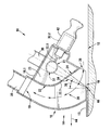
- a hollow laser ablation working head in accordance with the invention is generally indicated by reference numeral 10.
- the working head 10 is shown in use removing a coating 13 from a substrate 12.
- the coating 13 is in the form of a layer of paint which is radio-actively contaminated, and which is to be removed.
- the substance to be ablated may be hazardous for another reason, e.g. it may form volatile organic compounds when ablated.
- the working head 10 comprises a generally hollow body 14 formed by a wall 16. At a bottom of the body 14, there is provided an exposure opening 18 defining a planar bottom. The planar bottom will be moved over the substrate 12 to be cleaned in close proximity thereto.
- Attachment means in the form of a connector 20 for connection to a suction apparatus protrudes from the wall 16, around the extraction opening 19.
- an internal wall 22 having a first section 22.1 extending from the wall 16 adjacent a ventilation opening 26 integral with the exposure opening 18 obliquely inwardly to a position roughly in the centre of the hollow body 14, and thence curves smoothly toward one extremity of the extraction opening to a planar wall portion 16.1 generally opposite to the exposure opening 18.
- the wall portion 16.1 is adjacent the extraction opening connector 20 and defines a closed top of the body 14.
- the internal wall 22 demarcates roughly an internal corner area 23 of the hollow body 14.
- a beam port covered by a window 24 is provided within the first section 22.1. It is envisaged that the port may be open in some applications.
- a flow passage 28 is established generally from the ventilation opening 26, in conjunction with the exposure opening 18, internally toward the extraction opening connector 20.
- the flow passage 28 extends alongside, i.e. generally tangentially to, the internal wall 22.
- the flow passage 28 is defined at the opposed side by a curved portion of the wall 16 guiding the flow passage 28 toward the extraction opening connector 20. It is to be appreciated that the flow passage 28 is of generally aerodynamic form having no obstruction and no sharp corner or bend to inhibit flow.
- a laser connection means Adjacent the extraction opening connector 20, but on the opposed side of the internal wall section 22, i.e. within the area 23, there is provided a laser connection means in the form of a connector housing 30 secured to the hollow body 14.
- the connector housing 30, in one plane which can be seen in the drawing, is generally in line with the beam port or beam window 24 and the exposure opening 18 such that it will in use be aligned, in respect of said one plane, with a target area 40 which is to be ablated.
- the connector housing 30 accommodates an optical fibre leading from a laser machine. In other embodiment, another kind of beam transport device may be used.
- the housing 30 is shown without its lateral location at right angles to said one plane (i.e. its depth in relation to the drawing) being defined. In reality, it is displaced in said right angled plane from the level of the beam port 24.
- a first, oblique reflector 31 Aligned with the housing 30 and the optical fibre is a first, oblique reflector 31 which reflects the beam onto a second, complementary oblique reflector 32 which is aligned with and directs the beam via the beam port 24 and exposure opening 18 onto the target area.
- the second reflector 32 is connected via a pivoting shaft 32.1 to a drive motor 32.2 accommodated within a motor housing 42 which is secured to the (main) body 14.
- the motor 32.2 and an associated transmission and the shaft 32.1 operate as a scanning drive cyclically to tilt the reflector 32 to scan the beam 34 in lateral direction so as to treat a bandwidth, for example selected to be, typically, 30 mm.
- the scanning rate may be selected at about 10 Hz.
- a fast moving scanning drive may be obviated.
- the beam window 24 is oblique relative to the beam path leading toward the exposure opening 18.
- suction is applied via the extraction opening connector 20 to create a reduced or negative pressure within the hollow body 14 and to move air via the ventilation opening 26 and exposure opening 18 via the flow passage 28 toward the extraction opening connector 20 and the suction or extraction apparatus.
- the suction creates a reduced or negative pressure in the flow passage 28 from the exposure opening 18 to the extraction opening 19 and causes an air flow along the flow passage 28.
- appropriate measures will be taken to accumulate debris of the radio-active paint layer 13 at high integrity to enable the debris to be dealt with and stowed appropriately.
- the laser beam is directed at and focussed via the exposure opening 18 onto the substrate 12, more specifically the contaminated paint layer 13 to remove the paint layer 13 by ablation as indicated by reference numeral 40. It is significant that the beam 34 has an incidence angle generally indicated by reference numeral 36 onto the substrate 12 (bearing in mind that the exposure opening 18 will generally be parallel to the substrate 12).
- the angle 36 in this embodiment, is preferably about 30° to the normal to the exposure opening. The significance of this will be explained below.
- the extremely high energy transferred to the paint layer 13 by means of the laser beam 34 causes the paint particles to disintegrate into vapour and other gaseous constituents and small particles of solid and molten material to form.
- the heat generated at the area 40 explosively accelerates the gas and particles up to supersonic speed away from the substrate 12.
- the gas and particles are accelerated in a cone centred along the normal to a surface of the substrate 12 at the position 40 at an enclosed cone angle of up to about 110°.
- the concentration distribution of particles is typically bell-shaped having a peak concentration substantially normal to the substrate i.e. along the axis of the cone, and tapering off to the outside.
- the laser beam 34 is directed at an incidence angle 36, which is advantageously about 30°, to the normal to the substrate 12, thus causing passage of the laser beam through a much less dense area of the plume. This is of particular importance and is regarded by the Applicant as greatly enhancing efficiency of transmission of the energy onto the substrate, compared to other devices known to the Applicant.
- the working head 10 is moved in the direction of arrow 44 as ablation takes place. This movement, together with the bandwidth movement achieved by lateral scanning of the laser beam as hereinbefore described, results in the working head being traversed over the substrate in an area thereof in which laser ablation is required.
- the extraction opening connector 20 is virtually on axis relative to the exposure opening 18 and the position 40 from which the cone of debris emanates.
- the debris is carried away in the direction in which it moves naturally from the target area 40. This greatly enhances the integrity of removal of the debris.
- the beam window 24 is angled relative to the normal to the laser beam direction. This increases the cross-sectional area of the beam intersection with the beam window, which in turn causes reduced fluence at the window and reduces the heat load on the window.
- the window is thus generally at a lower temperature which renders it less prone to particles which do reach the window to melt and to attach to the window.
- the beam window is oriented to be alongside, i.e. substantially or generally tangential to, the flow passage. This has the effect of rendering the flow passage more aerodynamic, and also enhances the cooling effect of the air flowing past the beam window on the window. This increases cooling and cleaning of the beam window.
- the beam window is positioned remotely from the target area to increase the working distance and to increase the space in which the extraction air can interact with the debris and change the direction away from the window.
Landscapes
- Physics & Mathematics (AREA)
- Optics & Photonics (AREA)
- Engineering & Computer Science (AREA)
- Plasma & Fusion (AREA)
- Mechanical Engineering (AREA)
- Laser Beam Processing (AREA)
- Laser Surgery Devices (AREA)
Applications Claiming Priority (1)
| Application Number | Priority Date | Filing Date | Title |
|---|---|---|---|
| ZA200703305 | 2007-04-23 |
Publications (2)
| Publication Number | Publication Date |
|---|---|
| EP1985403A1 true EP1985403A1 (de) | 2008-10-29 |
| EP1985403B1 EP1985403B1 (de) | 2011-05-18 |
Family
ID=39637134
Family Applications (1)
| Application Number | Title | Priority Date | Filing Date |
|---|---|---|---|
| EP08007812A Not-in-force EP1985403B1 (de) | 2007-04-23 | 2008-04-23 | Laserablation |
Country Status (4)
| Country | Link |
|---|---|
| EP (1) | EP1985403B1 (de) |
| AT (1) | ATE509728T1 (de) |
| ES (1) | ES2367376T3 (de) |
| ZA (1) | ZA200803572B (de) |
Cited By (4)
| Publication number | Priority date | Publication date | Assignee | Title |
|---|---|---|---|---|
| EP2072155A1 (de) * | 2007-12-19 | 2009-06-24 | Airbus Espana, S.L. | Verfahren zur Herstellung und Reinigung von Werkzeugen zur Herstellung von Verbundmaterialkomponenten und entsprechende Vorrichtung |
| WO2017203431A1 (en) * | 2016-05-23 | 2017-11-30 | Arcelormittal | Method for preparing a precoated sheet and associated installation |
| WO2020148071A1 (de) * | 2019-01-16 | 2020-07-23 | RWE Nuclear GmbH | Verfahren und vorrichtung zum aufbereiten eines kontaminierten werkstücks |
| US20210245299A1 (en) * | 2020-02-10 | 2021-08-12 | Disco Corporation | Laser processing apparatus |
Families Citing this family (2)
| Publication number | Priority date | Publication date | Assignee | Title |
|---|---|---|---|---|
| RU2503890C1 (ru) * | 2012-06-04 | 2014-01-10 | Федеральное государственное бюджетное образовательное учреждение высшего профессионального образования Новосибирский государственный архитектурно-строительный университет (Сибстрин) | Охлаждаемое вытяжное защитное вентиляционное устройство |
| DE202023101363U1 (de) * | 2023-03-19 | 2023-03-24 | 4Jet Technologies Gmbh | Absaugvorrichtung und Laservorrichtung |
Citations (3)
| Publication number | Priority date | Publication date | Assignee | Title |
|---|---|---|---|---|
| JPS6254590A (ja) * | 1985-09-02 | 1987-03-10 | Toyota Motor Corp | 合成樹脂材料の切断方法 |
| US5780806A (en) * | 1995-07-25 | 1998-07-14 | Lockheed Idaho Technologies Company | Laser ablation system, and method of decontaminating surfaces |
| US20020134770A1 (en) * | 2001-03-22 | 2002-09-26 | Freiwald David A. | Laser ablation cleaning |
-
2008
- 2008-04-23 ES ES08007812T patent/ES2367376T3/es active Active
- 2008-04-23 AT AT08007812T patent/ATE509728T1/de not_active IP Right Cessation
- 2008-04-23 ZA ZA200803572A patent/ZA200803572B/en unknown
- 2008-04-23 EP EP08007812A patent/EP1985403B1/de not_active Not-in-force
Patent Citations (3)
| Publication number | Priority date | Publication date | Assignee | Title |
|---|---|---|---|---|
| JPS6254590A (ja) * | 1985-09-02 | 1987-03-10 | Toyota Motor Corp | 合成樹脂材料の切断方法 |
| US5780806A (en) * | 1995-07-25 | 1998-07-14 | Lockheed Idaho Technologies Company | Laser ablation system, and method of decontaminating surfaces |
| US20020134770A1 (en) * | 2001-03-22 | 2002-09-26 | Freiwald David A. | Laser ablation cleaning |
Cited By (8)
| Publication number | Priority date | Publication date | Assignee | Title |
|---|---|---|---|---|
| EP2072155A1 (de) * | 2007-12-19 | 2009-06-24 | Airbus Espana, S.L. | Verfahren zur Herstellung und Reinigung von Werkzeugen zur Herstellung von Verbundmaterialkomponenten und entsprechende Vorrichtung |
| WO2017203431A1 (en) * | 2016-05-23 | 2017-11-30 | Arcelormittal | Method for preparing a precoated sheet and associated installation |
| WO2017203321A1 (en) * | 2016-05-23 | 2017-11-30 | Arcelormittal | Method for preparing a precoated sheet and associated installation |
| CN109311123A (zh) * | 2016-05-23 | 2019-02-05 | 安赛乐米塔尔公司 | 用于制备预涂覆板的方法以及相关联的装置 |
| US20190193209A1 (en) * | 2016-05-23 | 2019-06-27 | Arcelormittal | Method for Preparing a Precoated Sheet and Associated Installation |
| CN109311123B (zh) * | 2016-05-23 | 2020-11-17 | 安赛乐米塔尔公司 | 用于制备预涂覆板的方法以及相关联的装置 |
| WO2020148071A1 (de) * | 2019-01-16 | 2020-07-23 | RWE Nuclear GmbH | Verfahren und vorrichtung zum aufbereiten eines kontaminierten werkstücks |
| US20210245299A1 (en) * | 2020-02-10 | 2021-08-12 | Disco Corporation | Laser processing apparatus |
Also Published As
| Publication number | Publication date |
|---|---|
| ATE509728T1 (de) | 2011-06-15 |
| EP1985403B1 (de) | 2011-05-18 |
| ES2367376T3 (es) | 2011-11-02 |
| ZA200803572B (en) | 2009-02-25 |
Similar Documents
| Publication | Publication Date | Title |
|---|---|---|
| EP1985403B1 (de) | Laserablation | |
| JP7487960B2 (ja) | 付着物除去方法及び付着物除去装置 | |
| JP4840110B2 (ja) | レーザ溶接装置およびレーザ溶接方法 | |
| US6288362B1 (en) | Method and apparatus for treating surfaces and ablating surface material | |
| US6437285B1 (en) | Method and apparatus for treating interior cylindrical surfaces and ablating surface material thereon | |
| CN103286445B (zh) | 一种激光精密加工设备除尘系统 | |
| JP3143457U (ja) | レーザ加工機用集塵装置 | |
| JP5983933B2 (ja) | 塗膜除去方法及びレーザー照射装置 | |
| KR102107377B1 (ko) | 레이저 클리닝 장치 | |
| JP7250241B1 (ja) | レーザー処理用回収装置、レーザー処理システム、及び、レーザー処理方法 | |
| TW200902208A (en) | Device and method for machining a workpiece by means of a laser beam, comprising suction and a lateral air supply | |
| JPH0569175A (ja) | レーザ加工装置 | |
| JP7088492B2 (ja) | レーザー除染装置、レーザー除染システム及びレーザー除染方法 | |
| KR20190062076A (ko) | 멀티 라인 레이저를 이용한 표면 처리 장치 | |
| WO2021200667A1 (ja) | コンクリートの表面処理方法、及び、レーザ処理済みコンクリート表面 | |
| JP3926433B2 (ja) | 核燃料ペレットからダストを除去する方法および装置 | |
| JP2022158656A (ja) | 光学機器保護装置およびレーザ加工装置 | |
| CN101945712A (zh) | 用于至少部分地去除涂层的方法和装置以及表面处理设备 | |
| JP5956650B1 (ja) | 表面処理装置 | |
| US6444097B1 (en) | Radioactive decontamination | |
| US20110253687A1 (en) | Mouth of a hood for sucking up fine particles, and laser device for ablating a surface layer of a wall comprising such a hood | |
| US8905743B2 (en) | Hood for sucking-up fine particles, and a device intended for the laser ablation of a surface layer of a wall and including such a hood | |
| CN118976984A (zh) | 一种激光焊接设备 | |
| JP6955664B2 (ja) | 表面処理装置 | |
| JP2020022978A (ja) | レーザ照射装置、流体供給装置、及び、レーザ加工方法 |
Legal Events
| Date | Code | Title | Description |
|---|---|---|---|
| PUAI | Public reference made under article 153(3) epc to a published international application that has entered the european phase |
Free format text: ORIGINAL CODE: 0009012 |
|
| AK | Designated contracting states |
Kind code of ref document: A1 Designated state(s): AT BE BG CH CY CZ DE DK EE ES FI FR GB GR HR HU IE IS IT LI LT LU LV MC MT NL NO PL PT RO SE SI SK TR |
|
| AX | Request for extension of the european patent |
Extension state: AL BA MK RS |
|
| 17P | Request for examination filed |
Effective date: 20090429 |
|
| 17Q | First examination report despatched |
Effective date: 20090528 |
|
| AKX | Designation fees paid |
Designated state(s): AT BE BG CH CY CZ DE DK EE ES FI FR GB GR HR HU IE IS IT LI LT LU LV MC MT NL NO PL PT RO SE SI SK TR |
|
| GRAP | Despatch of communication of intention to grant a patent |
Free format text: ORIGINAL CODE: EPIDOSNIGR1 |
|
| GRAS | Grant fee paid |
Free format text: ORIGINAL CODE: EPIDOSNIGR3 |
|
| GRAA | (expected) grant |
Free format text: ORIGINAL CODE: 0009210 |
|
| REG | Reference to a national code |
Ref country code: GB Ref legal event code: FG4D |
|
| REG | Reference to a national code |
Ref country code: CH Ref legal event code: EP |
|
| REG | Reference to a national code |
Ref country code: IE Ref legal event code: FG4D |
|
| REG | Reference to a national code |
Ref country code: DE Ref legal event code: R096 Ref document number: 602008006961 Country of ref document: DE Effective date: 20110630 |
|
| REG | Reference to a national code |
Ref country code: NL Ref legal event code: T3 |
|
| REG | Reference to a national code |
Ref country code: SE Ref legal event code: TRGR |
|
| REG | Reference to a national code |
Ref country code: CH Ref legal event code: NV Representative=s name: E. BLUM & CO. AG PATENT- UND MARKENANWAELTE VSP |
|
| PG25 | Lapsed in a contracting state [announced via postgrant information from national office to epo] |
Ref country code: PT Free format text: LAPSE BECAUSE OF FAILURE TO SUBMIT A TRANSLATION OF THE DESCRIPTION OR TO PAY THE FEE WITHIN THE PRESCRIBED TIME-LIMIT Effective date: 20110919 Ref country code: HR Free format text: LAPSE BECAUSE OF FAILURE TO SUBMIT A TRANSLATION OF THE DESCRIPTION OR TO PAY THE FEE WITHIN THE PRESCRIBED TIME-LIMIT Effective date: 20110518 Ref country code: NO Free format text: LAPSE BECAUSE OF FAILURE TO SUBMIT A TRANSLATION OF THE DESCRIPTION OR TO PAY THE FEE WITHIN THE PRESCRIBED TIME-LIMIT Effective date: 20110818 Ref country code: LT Free format text: LAPSE BECAUSE OF FAILURE TO SUBMIT A TRANSLATION OF THE DESCRIPTION OR TO PAY THE FEE WITHIN THE PRESCRIBED TIME-LIMIT Effective date: 20110518 |
|
| REG | Reference to a national code |
Ref country code: ES Ref legal event code: FG2A Ref document number: 2367376 Country of ref document: ES Kind code of ref document: T3 Effective date: 20111102 |
|
| PG25 | Lapsed in a contracting state [announced via postgrant information from national office to epo] |
Ref country code: SI Free format text: LAPSE BECAUSE OF FAILURE TO SUBMIT A TRANSLATION OF THE DESCRIPTION OR TO PAY THE FEE WITHIN THE PRESCRIBED TIME-LIMIT Effective date: 20110518 Ref country code: LV Free format text: LAPSE BECAUSE OF FAILURE TO SUBMIT A TRANSLATION OF THE DESCRIPTION OR TO PAY THE FEE WITHIN THE PRESCRIBED TIME-LIMIT Effective date: 20110518 Ref country code: CY Free format text: LAPSE BECAUSE OF FAILURE TO SUBMIT A TRANSLATION OF THE DESCRIPTION OR TO PAY THE FEE WITHIN THE PRESCRIBED TIME-LIMIT Effective date: 20110518 Ref country code: GR Free format text: LAPSE BECAUSE OF FAILURE TO SUBMIT A TRANSLATION OF THE DESCRIPTION OR TO PAY THE FEE WITHIN THE PRESCRIBED TIME-LIMIT Effective date: 20110819 Ref country code: AT Free format text: LAPSE BECAUSE OF FAILURE TO SUBMIT A TRANSLATION OF THE DESCRIPTION OR TO PAY THE FEE WITHIN THE PRESCRIBED TIME-LIMIT Effective date: 20110518 Ref country code: IS Free format text: LAPSE BECAUSE OF FAILURE TO SUBMIT A TRANSLATION OF THE DESCRIPTION OR TO PAY THE FEE WITHIN THE PRESCRIBED TIME-LIMIT Effective date: 20110918 |
|
| PG25 | Lapsed in a contracting state [announced via postgrant information from national office to epo] |
Ref country code: EE Free format text: LAPSE BECAUSE OF FAILURE TO SUBMIT A TRANSLATION OF THE DESCRIPTION OR TO PAY THE FEE WITHIN THE PRESCRIBED TIME-LIMIT Effective date: 20110518 |
|
| PG25 | Lapsed in a contracting state [announced via postgrant information from national office to epo] |
Ref country code: SK Free format text: LAPSE BECAUSE OF FAILURE TO SUBMIT A TRANSLATION OF THE DESCRIPTION OR TO PAY THE FEE WITHIN THE PRESCRIBED TIME-LIMIT Effective date: 20110518 Ref country code: RO Free format text: LAPSE BECAUSE OF FAILURE TO SUBMIT A TRANSLATION OF THE DESCRIPTION OR TO PAY THE FEE WITHIN THE PRESCRIBED TIME-LIMIT Effective date: 20110518 Ref country code: PL Free format text: LAPSE BECAUSE OF FAILURE TO SUBMIT A TRANSLATION OF THE DESCRIPTION OR TO PAY THE FEE WITHIN THE PRESCRIBED TIME-LIMIT Effective date: 20110518 Ref country code: DK Free format text: LAPSE BECAUSE OF FAILURE TO SUBMIT A TRANSLATION OF THE DESCRIPTION OR TO PAY THE FEE WITHIN THE PRESCRIBED TIME-LIMIT Effective date: 20110518 |
|
| PLBE | No opposition filed within time limit |
Free format text: ORIGINAL CODE: 0009261 |
|
| STAA | Information on the status of an ep patent application or granted ep patent |
Free format text: STATUS: NO OPPOSITION FILED WITHIN TIME LIMIT |
|
| 26N | No opposition filed |
Effective date: 20120221 |
|
| REG | Reference to a national code |
Ref country code: DE Ref legal event code: R097 Ref document number: 602008006961 Country of ref document: DE Effective date: 20120221 |
|
| PG25 | Lapsed in a contracting state [announced via postgrant information from national office to epo] |
Ref country code: MC Free format text: LAPSE BECAUSE OF NON-PAYMENT OF DUE FEES Effective date: 20120430 |
|
| REG | Reference to a national code |
Ref country code: IE Ref legal event code: MM4A |
|
| PG25 | Lapsed in a contracting state [announced via postgrant information from national office to epo] |
Ref country code: IE Free format text: LAPSE BECAUSE OF NON-PAYMENT OF DUE FEES Effective date: 20120423 |
|
| PG25 | Lapsed in a contracting state [announced via postgrant information from national office to epo] |
Ref country code: BG Free format text: LAPSE BECAUSE OF FAILURE TO SUBMIT A TRANSLATION OF THE DESCRIPTION OR TO PAY THE FEE WITHIN THE PRESCRIBED TIME-LIMIT Effective date: 20110818 |
|
| PG25 | Lapsed in a contracting state [announced via postgrant information from national office to epo] |
Ref country code: MT Free format text: LAPSE BECAUSE OF FAILURE TO SUBMIT A TRANSLATION OF THE DESCRIPTION OR TO PAY THE FEE WITHIN THE PRESCRIBED TIME-LIMIT Effective date: 20110518 |
|
| PG25 | Lapsed in a contracting state [announced via postgrant information from national office to epo] |
Ref country code: TR Free format text: LAPSE BECAUSE OF FAILURE TO SUBMIT A TRANSLATION OF THE DESCRIPTION OR TO PAY THE FEE WITHIN THE PRESCRIBED TIME-LIMIT Effective date: 20110518 |
|
| PG25 | Lapsed in a contracting state [announced via postgrant information from national office to epo] |
Ref country code: LU Free format text: LAPSE BECAUSE OF NON-PAYMENT OF DUE FEES Effective date: 20120423 |
|
| PG25 | Lapsed in a contracting state [announced via postgrant information from national office to epo] |
Ref country code: HU Free format text: LAPSE BECAUSE OF FAILURE TO SUBMIT A TRANSLATION OF THE DESCRIPTION OR TO PAY THE FEE WITHIN THE PRESCRIBED TIME-LIMIT Effective date: 20080423 |
|
| PGFP | Annual fee paid to national office [announced via postgrant information from national office to epo] |
Ref country code: ES Payment date: 20150327 Year of fee payment: 8 |
|
| PGFP | Annual fee paid to national office [announced via postgrant information from national office to epo] |
Ref country code: GB Payment date: 20150422 Year of fee payment: 8 Ref country code: FI Payment date: 20150409 Year of fee payment: 8 Ref country code: CZ Payment date: 20150403 Year of fee payment: 8 Ref country code: SE Payment date: 20150413 Year of fee payment: 8 Ref country code: CH Payment date: 20150414 Year of fee payment: 8 |
|
| PGFP | Annual fee paid to national office [announced via postgrant information from national office to epo] |
Ref country code: BE Payment date: 20150413 Year of fee payment: 8 Ref country code: IT Payment date: 20150422 Year of fee payment: 8 Ref country code: NL Payment date: 20150409 Year of fee payment: 8 |
|
| PG25 | Lapsed in a contracting state [announced via postgrant information from national office to epo] |
Ref country code: BE Free format text: LAPSE BECAUSE OF NON-PAYMENT OF DUE FEES Effective date: 20160430 |
|
| REG | Reference to a national code |
Ref country code: FR Ref legal event code: PLFP Year of fee payment: 9 |
|
| REG | Reference to a national code |
Ref country code: SE Ref legal event code: EUG |
|
| REG | Reference to a national code |
Ref country code: CH Ref legal event code: PL |
|
| REG | Reference to a national code |
Ref country code: NL Ref legal event code: MM Effective date: 20160501 |
|
| GBPC | Gb: european patent ceased through non-payment of renewal fee |
Effective date: 20160423 |
|
| PG25 | Lapsed in a contracting state [announced via postgrant information from national office to epo] |
Ref country code: LI Free format text: LAPSE BECAUSE OF NON-PAYMENT OF DUE FEES Effective date: 20160430 Ref country code: FI Free format text: LAPSE BECAUSE OF NON-PAYMENT OF DUE FEES Effective date: 20160423 Ref country code: NL Free format text: LAPSE BECAUSE OF NON-PAYMENT OF DUE FEES Effective date: 20160501 Ref country code: GB Free format text: LAPSE BECAUSE OF NON-PAYMENT OF DUE FEES Effective date: 20160423 Ref country code: CZ Free format text: LAPSE BECAUSE OF NON-PAYMENT OF DUE FEES Effective date: 20160423 Ref country code: CH Free format text: LAPSE BECAUSE OF NON-PAYMENT OF DUE FEES Effective date: 20160430 |
|
| PG25 | Lapsed in a contracting state [announced via postgrant information from national office to epo] |
Ref country code: IT Free format text: LAPSE BECAUSE OF NON-PAYMENT OF DUE FEES Effective date: 20160423 Ref country code: SE Free format text: LAPSE BECAUSE OF NON-PAYMENT OF DUE FEES Effective date: 20160424 |
|
| REG | Reference to a national code |
Ref country code: FR Ref legal event code: PLFP Year of fee payment: 10 |
|
| REG | Reference to a national code |
Ref country code: FR Ref legal event code: PLFP Year of fee payment: 11 |
|
| PG25 | Lapsed in a contracting state [announced via postgrant information from national office to epo] |
Ref country code: ES Free format text: LAPSE BECAUSE OF NON-PAYMENT OF DUE FEES Effective date: 20160424 |
|
| REG | Reference to a national code |
Ref country code: ES Ref legal event code: FD2A Effective date: 20181204 |
|
| PGFP | Annual fee paid to national office [announced via postgrant information from national office to epo] |
Ref country code: FR Payment date: 20220422 Year of fee payment: 15 Ref country code: DE Payment date: 20220420 Year of fee payment: 15 |
|
| REG | Reference to a national code |
Ref country code: DE Ref legal event code: R119 Ref document number: 602008006961 Country of ref document: DE |
|
| PG25 | Lapsed in a contracting state [announced via postgrant information from national office to epo] |
Ref country code: FR Free format text: LAPSE BECAUSE OF NON-PAYMENT OF DUE FEES Effective date: 20230430 Ref country code: DE Free format text: LAPSE BECAUSE OF NON-PAYMENT OF DUE FEES Effective date: 20231103 |