EP1985532A2 - Vorrichtung zur Positionierung von Fahrradkomponenten - Google Patents
Vorrichtung zur Positionierung von Fahrradkomponenten Download PDFInfo
- Publication number
- EP1985532A2 EP1985532A2 EP07118383A EP07118383A EP1985532A2 EP 1985532 A2 EP1985532 A2 EP 1985532A2 EP 07118383 A EP07118383 A EP 07118383A EP 07118383 A EP07118383 A EP 07118383A EP 1985532 A2 EP1985532 A2 EP 1985532A2
- Authority
- EP
- European Patent Office
- Prior art keywords
- release
- positioning
- bicycle component
- positioning device
- input member
- Prior art date
- Legal status (The legal status is an assumption and is not a legal conclusion. Google has not performed a legal analysis and makes no representation as to the accuracy of the status listed.)
- Granted
Links
Images





Classifications
-
- B—PERFORMING OPERATIONS; TRANSPORTING
- B62—LAND VEHICLES FOR TRAVELLING OTHERWISE THAN ON RAILS
- B62M—RIDER PROPULSION OF WHEELED VEHICLES OR SLEDGES; POWERED PROPULSION OF SLEDGES OR SINGLE-TRACK CYCLES; TRANSMISSIONS SPECIALLY ADAPTED FOR SUCH VEHICLES
- B62M25/00—Actuators for gearing speed-change mechanisms specially adapted for cycles
- B62M25/02—Actuators for gearing speed-change mechanisms specially adapted for cycles with mechanical transmitting systems, e.g. cables, levers
- B62M25/04—Actuators for gearing speed-change mechanisms specially adapted for cycles with mechanical transmitting systems, e.g. cables, levers hand actuated
-
- B—PERFORMING OPERATIONS; TRANSPORTING
- B62—LAND VEHICLES FOR TRAVELLING OTHERWISE THAN ON RAILS
- B62K—CYCLES; CYCLE FRAMES; CYCLE STEERING DEVICES; RIDER-OPERATED TERMINAL CONTROLS SPECIALLY ADAPTED FOR CYCLES; CYCLE AXLE SUSPENSIONS; CYCLE SIDECARS, FORECARS, OR THE LIKE
- B62K23/00—Rider-operated controls specially adapted for cycles, i.e. means for initiating control operations, e.g. levers, grips
- B62K23/02—Rider-operated controls specially adapted for cycles, i.e. means for initiating control operations, e.g. levers, grips hand actuated
- B62K23/06—Levers
-
- B—PERFORMING OPERATIONS; TRANSPORTING
- B62—LAND VEHICLES FOR TRAVELLING OTHERWISE THAN ON RAILS
- B62M—RIDER PROPULSION OF WHEELED VEHICLES OR SLEDGES; POWERED PROPULSION OF SLEDGES OR SINGLE-TRACK CYCLES; TRANSMISSIONS SPECIALLY ADAPTED FOR SUCH VEHICLES
- B62M9/00—Transmissions characterised by use of an endless chain, belt, or the like
- B62M9/04—Transmissions characterised by use of an endless chain, belt, or the like of changeable ratio
- B62M9/06—Transmissions characterised by use of an endless chain, belt, or the like of changeable ratio using a single chain, belt, or the like
- B62M9/10—Transmissions characterised by use of an endless chain, belt, or the like of changeable ratio using a single chain, belt, or the like involving different-sized wheels, e.g. rear sprocket chain wheels selectively engaged by the chain, belt, or the like
- B62M9/12—Transmissions characterised by use of an endless chain, belt, or the like of changeable ratio using a single chain, belt, or the like involving different-sized wheels, e.g. rear sprocket chain wheels selectively engaged by the chain, belt, or the like the chain, belt, or the like being laterally shiftable, e.g. using a rear derailleur
-
- B—PERFORMING OPERATIONS; TRANSPORTING
- B62—LAND VEHICLES FOR TRAVELLING OTHERWISE THAN ON RAILS
- B62M—RIDER PROPULSION OF WHEELED VEHICLES OR SLEDGES; POWERED PROPULSION OF SLEDGES OR SINGLE-TRACK CYCLES; TRANSMISSIONS SPECIALLY ADAPTED FOR SUCH VEHICLES
- B62M9/00—Transmissions characterised by use of an endless chain, belt, or the like
- B62M9/04—Transmissions characterised by use of an endless chain, belt, or the like of changeable ratio
- B62M9/06—Transmissions characterised by use of an endless chain, belt, or the like of changeable ratio using a single chain, belt, or the like
- B62M9/10—Transmissions characterised by use of an endless chain, belt, or the like of changeable ratio using a single chain, belt, or the like involving different-sized wheels, e.g. rear sprocket chain wheels selectively engaged by the chain, belt, or the like
- B62M9/12—Transmissions characterised by use of an endless chain, belt, or the like of changeable ratio using a single chain, belt, or the like involving different-sized wheels, e.g. rear sprocket chain wheels selectively engaged by the chain, belt, or the like the chain, belt, or the like being laterally shiftable, e.g. using a rear derailleur
- B62M9/121—Rear derailleurs
- B62M9/124—Mechanisms for shifting laterally
- B62M9/1244—Mechanisms for shifting laterally limiting or positioning the movement
- B62M9/1246—Mechanisms for shifting laterally limiting or positioning the movement using cams or plates
-
- B—PERFORMING OPERATIONS; TRANSPORTING
- B62—LAND VEHICLES FOR TRAVELLING OTHERWISE THAN ON RAILS
- B62M—RIDER PROPULSION OF WHEELED VEHICLES OR SLEDGES; POWERED PROPULSION OF SLEDGES OR SINGLE-TRACK CYCLES; TRANSMISSIONS SPECIALLY ADAPTED FOR SUCH VEHICLES
- B62M9/00—Transmissions characterised by use of an endless chain, belt, or the like
- B62M9/04—Transmissions characterised by use of an endless chain, belt, or the like of changeable ratio
- B62M9/06—Transmissions characterised by use of an endless chain, belt, or the like of changeable ratio using a single chain, belt, or the like
- B62M9/10—Transmissions characterised by use of an endless chain, belt, or the like of changeable ratio using a single chain, belt, or the like involving different-sized wheels, e.g. rear sprocket chain wheels selectively engaged by the chain, belt, or the like
- B62M9/12—Transmissions characterised by use of an endless chain, belt, or the like of changeable ratio using a single chain, belt, or the like involving different-sized wheels, e.g. rear sprocket chain wheels selectively engaged by the chain, belt, or the like the chain, belt, or the like being laterally shiftable, e.g. using a rear derailleur
- B62M9/131—Front derailleurs
- B62M9/134—Mechanisms for shifting laterally
- B62M9/1344—Mechanisms for shifting laterally limiting or positioning the movement
- B62M9/1346—Mechanisms for shifting laterally limiting or positioning the movement using cams or plates
-
- Y—GENERAL TAGGING OF NEW TECHNOLOGICAL DEVELOPMENTS; GENERAL TAGGING OF CROSS-SECTIONAL TECHNOLOGIES SPANNING OVER SEVERAL SECTIONS OF THE IPC; TECHNICAL SUBJECTS COVERED BY FORMER USPC CROSS-REFERENCE ART COLLECTIONS [XRACs] AND DIGESTS
- Y10—TECHNICAL SUBJECTS COVERED BY FORMER USPC
- Y10T—TECHNICAL SUBJECTS COVERED BY FORMER US CLASSIFICATION
- Y10T74/00—Machine element or mechanism
- Y10T74/20—Control lever and linkage systems
- Y10T74/20396—Hand operated
-
- Y—GENERAL TAGGING OF NEW TECHNOLOGICAL DEVELOPMENTS; GENERAL TAGGING OF CROSS-SECTIONAL TECHNOLOGIES SPANNING OVER SEVERAL SECTIONS OF THE IPC; TECHNICAL SUBJECTS COVERED BY FORMER USPC CROSS-REFERENCE ART COLLECTIONS [XRACs] AND DIGESTS
- Y10—TECHNICAL SUBJECTS COVERED BY FORMER USPC
- Y10T—TECHNICAL SUBJECTS COVERED BY FORMER US CLASSIFICATION
- Y10T74/00—Machine element or mechanism
- Y10T74/20—Control lever and linkage systems
- Y10T74/20396—Hand operated
- Y10T74/20402—Flexible transmitter [e.g., Bowden cable]
- Y10T74/2042—Flexible transmitter [e.g., Bowden cable] and hand operator
- Y10T74/20438—Single rotatable lever [e.g., for bicycle brake or derailleur]
Definitions
- This invention generally relates to a bicycle component positioning device. More specifically, the present invention relates to a bicycle component positioning device for a bicycle component such as a derailleur or shifter, which has the same relatively easy action when moved in two opposite directions, yet is reliably retained.
- Bicycling is becoming an increasingly more popular form of recreation as well as a means of transportation. Moreover, bicycling has become a very popular competitive sport for both amateurs and professionals. Whether the bicycle is used for recreation, transportation or competition, the bicycle industry is constantly improving the various components of the bicycle such as derailleurs and shifters.
- One object of the present invention is to provide a bicycle component positioning device, which moves smoothly and reliably, yet is reliably retained in different positions.
- Another object of the present invention is to provide a bicycle component positioning device, which is relatively simple and inexpensive to manufacture and/or assemble.
- a bicycle component positioning device which comprises a fixed structure, a positioning member, a first restricting member and a second restricting member.
- the positioning member is movably coupled with respect to the fixed structure.
- the first restricting member is operatively engaged with the positioning member to only restrict movement of the positioning member in a first moving direction when the positioning member is in one of predetermined positions.
- the second restricting member is operatively engaged with the positioning member to only restrict movement of the positioning member in a second moving direction when the positioning member is in one of predetermined positions.
- hydraulic or pneumatic lines constitute derailleur operating members that can operatively connect the bicycle component positioning device 38 to one of a shifter.
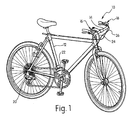
- the positioning device 38 is coupled to a link member 36a of the linkage mechanism 36 for moving the linkage mechanism 36 between the innermost or retracted position ( Figure 3 ) to the outermost or extended position ( Figure 4 ) with respect to the frame 12.
- the positioning device 38 can also maintain the chain guide 34 in a middle or intermediate position (not shown).
- the positioning device 38 firmly positions the chain guide 34 in one of a plurality of operating positions.
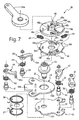
- the fixed structure 40 basically includes a first housing part 50, a second housing part 51, a mounting plate 52 and a main pivot axle 53.
- the first and second housing parts 50 and 51 form an enclosure with the first housing part 50 being fixed to the base member 30.
- the mounting plate 52 is non-movably mounted within the first and second housing parts 50 and 51.
- the main pivot axle 53 defines the main pivot axis A of the fixed structure 40 with the input member 43, the release plate 46 and the positioning plate 48 being mounted to rotate about the main pivot axis A in the first and second moving directions B and C.
- the input or operating member 43 is pivotally mounted on the main pivot axle 53 of the fixed structure 40 such that it pivots about the main pivot axis A.
- the input member 43 is movably coupled with respect to the fixed structure 40 to move in the first and second moving directions B and C from the neutral rest position.
- the input member 43 is preferably biased to a stationary neutral or rest position with respect to the fixed structure 40.
- a biasing arrangement is provided that includes a pair of torsion springs 58 and 59 arranged between the input member 43 and the mounting plate 52.
- the torsion springs 58 and 59 act as biasing elements that maintains the input member 43 in the stationary rest position.
- the input member 43 has a trigger action with the first torsion spring 58 urging the input member 43 to the stationary rest position when the input member 43 is pivoted in the first moving direction B.
- the second torsion spring 59 urges the input member 43 to the stationary rest position when the input member 43 is pivoted in the second moving direction C. Accordingly, when the shifter 18 is operated, the input member 43 is either pushed or pulled in response to movement of the shift lever 18a of the shifter 18 with the shift lever 18a and the input member 43 both automatically returning to their stationary rest positions.
- the input member 43 includes a base part 43a with a pivot hole and a cable attachment lever 43b extending outwardly from the base part 43a.
- the cable attachment lever 43b is provided with a cable attachment structure 43c in the form of a hole for attaching the control cable 26 thereto. Accordingly, when the shifter 18 is operated, the cable 26 either pulls or pushes the cable attachment lever 43b such that the input member 43 selectively pivots in either the first moving direction B or the second moving direction C.
- the positioning plate 48 has the derailleur link member 36a fixedly attached thereto such that the movement of the input member 43 from the shifter 18 is transmitted to the chain guide 34 as explained below.
- the input member 43 includes a pair of pivot pins 61 and 62 for pivotally supporting the first and second release pawls 44 and 45.
- the first release pawl 44 is biased in a counterclockwise direction in Figure 5 about the pivot pin 61 to contact an abutment 52a formed on the edge of the mounting plate 52 by a torsion spring 63 when the input member 43 is in the neutral rest position.
- the second release pawl 45 is biased in a clockwise direction in Figure 5 about the second pivot pin 62 to contact an abutment 52b formed on the edge of the mounting plate 52 by a torsion spring 64 when the input member 43 is in the neutral rest position.
- the first and second release pawls 44 and 45 are disengaged from the release plate 46.
- the first and second release pawls 44 and 45 are normally disengaged from the release plate 46 by projections 44a and 45a that rest on the abutments 52a and 52b when the input member 43 is in the neutral rest position.
- the projection 44a of the first release pawl 44 rides off of the abutment 52a and then engages the release plate 46.
- the projection 45a of the second release pawl 45 rides off of the abutment 52a and then engages the release plate 46.
- the release plate 46 is basically a flat metal plate that rotates on the main pivot axle 53.
- the release plate 46 has a peripheral edge with a set of first ratchet teeth 46a, a set of second ratchet teeth 46b and a set of release teeth 46c.
- the release plate 46 is operatively coupled to the first and second restricting members 41 and 42 to selectively disengage the first restricting pawl 41 to enable movement of the positioning plate 48 when the input member 43 is moved from the neutral rest position in the first moving direction B.
- This movement of the input member 43 in the first moving direction B also causes the release plate 46 to lift the second restricting pawl 42 as the positioning plate 48 moves to the next operating position, and then reengage the first and second restricting pawls 41 and 42 against the positioning plate 48 to prevent rotational movement.
- the second restricting pawl 42 is selectively disengaged from the positioning plate 48 to enable movement of the positioning plate 48 in response to the input member 43 being moved from the neutral rest position in the second moving direction C.
- This movement of the input member 43 in the second moving direction C also causes the release plate 46 to sequentially lift the first restricting pawl 41 as the positioning plate 48 moves to the next operating position, and then reengage the first and second restricting pawls 41 and 42 against the positioning plate 48 to prevent rotational movement.
- first ratchet teeth 46a are selectively engaged by the first release pawl 44 when the input member 43 is moved from the neutral rest position in the first moving direction B so that the movement of the input member 43 in the first moving direction B causes the release plate 46 to also move in the first moving direction B.
- the second ratchet teeth are selectively engaged by the second release pawl 45 in response to the input member 43 being moved from the neutral position in the second moving direction C so that the movement of the input member 43 in the second moving direction C causes the release plate 46 to also move in the second moving direction C.
- the release plate 46 is operatively coupled to the input member 43 via the first and second release pawls 44 and 45.
- the release teeth 46c selectively engage the first and second restricting members 41 and 42 to selectively disengage the first and second restricting members 41 and 42 from the positioning plate 48 when the input member 43 is moved from the neutral position in the first and second moving directions B and C, respectively.
- the release plate 46 also has an arcuate slot 46d and a pair of spring receiving apertures 46e.
- the slot 46d and receiving apertures 46e are used to control the relative movement between the release plate 46 and the positioning plate 48.
- the release plate 46 and the positioning plate 48 are movable relative to each other by a predetermined limited amount in both moving directions B and C.
- the release plate 46 In neutral rest position, the release plate 46 is maintained in a neutral position as shown in Figure 5 by a biasing arrangement that includes a pair of biasing elements in the form of coil compression springs 65.
- This biasing arrangement is disposed to maintain the release plate 46 in a stationary intermediate position with one of the release teeth 46c disposed between the first and second restricting pawls 41 and 42 when the input member 43 returns to the neutral rest position.
- the biasing elements or springs 65 are disposed between the release plate 46 and the positioning plate 48.
- the projections 48b engage recesses in the link member 36a so that the link member 36a and the positioning plate 48 move together.
- the pin 48c is disposed in the slot 46d of the release plate 46 so that the positioning plate 48 is movably coupled with respect to the release plate 46 through a limited range of movement.
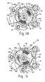
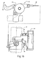
- the slot 46d of the release plate 46 and the pin 48c of the positioning plate 48 are dimensioned so that the release plate 46 initially moves with respect to the positioning plate 48 as seen in Figures 8 to 10 and Figures 14 to 16 . This allows for one of the first and second restricting pawls 41 and 42 to be lifted out of the path of the positioning teeth 48a.
- the release plate 46 and the positioning plate 48 rotate together such that the next one of the positioning teeth 48a moves between the first and second restricting pawls 41 and 42.
- the first and second restricting pawls 41 and 42 are sequentially lifted to perform a shifting operation.
- the biasing elements or springs 65 are disposed in the spring receiving apertures 46e and 48d to maintain the release plate 46 in a stationary intermediate position with one of the release teeth 46c disposed between the first and second restricting pawls 41 and 42 when the input member 43 returns to the neutral rest position. In the neutral rest position, the release teeth 46c and the positioning teeth 48a are also aligned.
- One of the springs 65 is compressed during initial movement of the input member 43 because the first and second restricting pawls 41 and 42 prevent the positioning plate 48 from initially rotating with the release plate 46. When the positioning plate 48 reaches the position as seen in Figures 10 , the positioning plate 48 is disengaged from the first restricting pawl 41.
- the input member 43 constitutes a rider shift control operable lever, which moves the positioning plate 48 and the wire takeup member 39.
- the wire takeup member 39 has a wire connection point 39a for attaching one end of an inner wire of a flexible control cable 26' thereto. The other end of the inner wire of the flexible control cable 26' is attached to a link member of the front derailleur 22.
- the positioning plate 48 is operatively coupled to the derailleur chain guide 34 via the flexible control cable 26' to move the chain guide 34 between a retracted position and an extended position in response to the input member 43 being moved from the neutral position in the first and second moving directions B and C.
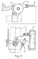
- a second one of the positioning teeth 48a and a second one of the release teeth 46c are located between the first and second restricting members or pawls 41 and 42 to prevent rotational movement of the positioning plate 48. Then when the input member 43 is initially moved in the second moving direction C from the neutral rest position to a position in which the second release pawl 45 initially engages one of the ratchet teeth 46b of the release plate 46, as seen in Figure 13 , the release plate 46 and the positioning plate 48 remains stationary.
Landscapes
- Engineering & Computer Science (AREA)
- Mechanical Engineering (AREA)
- Chemical & Material Sciences (AREA)
- Combustion & Propulsion (AREA)
- Transportation (AREA)
- Mechanical Control Devices (AREA)
- Gear-Shifting Mechanisms (AREA)
- Automatic Assembly (AREA)
Applications Claiming Priority (1)
| Application Number | Priority Date | Filing Date | Title |
|---|---|---|---|
| US11/740,514 US9334020B2 (en) | 2007-04-26 | 2007-04-26 | Bicycle component positioning device |
Publications (4)
| Publication Number | Publication Date |
|---|---|
| EP1985532A2 true EP1985532A2 (de) | 2008-10-29 |
| EP1985532A3 EP1985532A3 (de) | 2009-06-24 |
| EP1985532B1 EP1985532B1 (de) | 2012-11-21 |
| EP1985532B2 EP1985532B2 (de) | 2017-03-15 |
Family
ID=38705080
Family Applications (1)
| Application Number | Title | Priority Date | Filing Date |
|---|---|---|---|
| EP07118383.4A Not-in-force EP1985532B2 (de) | 2007-04-26 | 2007-10-12 | Vorrichtung zur Positionierung von Fahrradkomponenten |
Country Status (4)
| Country | Link |
|---|---|
| US (1) | US9334020B2 (de) |
| EP (1) | EP1985532B2 (de) |
| CN (1) | CN101293557A (de) |
| TW (1) | TW200842080A (de) |
Cited By (1)
| Publication number | Priority date | Publication date | Assignee | Title |
|---|---|---|---|---|
| EP2428441A1 (de) * | 2010-09-09 | 2012-03-14 | Chang Hui Lin | Kettenschaltung |
Families Citing this family (15)
| Publication number | Priority date | Publication date | Assignee | Title |
|---|---|---|---|---|
| JP5268572B2 (ja) * | 2008-11-06 | 2013-08-21 | 株式会社ミクニ | アクセル操作装置 |
| US9592879B2 (en) * | 2011-05-26 | 2017-03-14 | Shimano Inc. | Shift positioning mechanism |
| US8857839B2 (en) | 2013-03-13 | 2014-10-14 | Zike, Llc | Lever drive system for a scooter |
| US20140265220A1 (en) * | 2013-03-15 | 2014-09-18 | Zike, Llc | Low Profile Derailleur For Chain Driven Personal Vehicle |
| BR202013022462U2 (pt) * | 2013-09-03 | 2015-08-11 | Elias Rodrigues De Souza | Dispositivo introduzido em bicicletas |
| US10597109B2 (en) * | 2014-01-28 | 2020-03-24 | Shimano Inc. | Bicycle component positioning device |
| US9604691B2 (en) * | 2014-02-20 | 2017-03-28 | Shimano Inc. | Bicycle operating device |
| US9457871B2 (en) * | 2014-09-08 | 2016-10-04 | Shimano Inc. | Bicycle front derailleur |
| US10005513B2 (en) * | 2015-07-06 | 2018-06-26 | Shimano Inc. | Bicycle operating device |
| US10207768B2 (en) * | 2016-03-29 | 2019-02-19 | Shimano Inc. | Bicycle operating device |
| KR102453588B1 (ko) * | 2016-11-18 | 2022-10-11 | 현대자동차주식회사 | 차량용 시트의 릴리즈 액추에이터 |
| IT201700015361A1 (it) | 2017-02-13 | 2018-08-13 | Campagnolo Srl | Dispositivo meccanico di azionamento del cavo di comando di un deragliatore di bicicletta |
| US10232909B2 (en) * | 2017-03-06 | 2019-03-19 | Shimano Inc. | Bicycle operating device |
| US10259533B2 (en) * | 2017-03-06 | 2019-04-16 | Shimano Inc. | Bicycle operating device |
| US11072392B2 (en) | 2018-11-08 | 2021-07-27 | Shimano Inc. | Bicycle operating device |
Citations (3)
| Publication number | Priority date | Publication date | Assignee | Title |
|---|---|---|---|---|
| US3901095A (en) | 1974-06-17 | 1975-08-26 | Joseph W Wechsler | Bicycle gear shift |
| US6220111B1 (en) | 1999-08-10 | 2001-04-24 | Chieh-Yuan Chen | Bicycle speed changing device |
| EP1118534B1 (de) | 2000-01-22 | 2005-08-24 | SRAM Deutschland GmbH | Schalteinrichtung für Fahrradgetriebe |
Family Cites Families (58)
| Publication number | Priority date | Publication date | Assignee | Title |
|---|---|---|---|---|
| US1442003A (en) * | 1920-05-22 | 1923-01-09 | John W Rohrer | Spring-pawl drive for stokers |
| IT965346B (it) | 1971-09-16 | 1974-01-31 | Mathauser W | Perfezionamento nei cambi di velocita azionati idraulicamente per biciclette e simili |
| JPS5128934A (ja) | 1974-09-06 | 1976-03-11 | Shimano Industrial Co | Gaisohensokuki |
| JPS5118046A (ja) | 1974-08-06 | 1976-02-13 | Shimano Industrial Co | Gaisohensokuki |
| JPS5150141A (ja) | 1974-10-23 | 1976-05-01 | Shimano Industrial Co | Gaisohensokuki |
| JPS5143541A (en) | 1974-10-12 | 1976-04-14 | Shimano Industrial Co | Gaisohensokukino kirikaesochi |
| JPS5215033A (en) | 1975-07-24 | 1977-02-04 | Bridgestone Cycle Ind Co | External transmission for bicycle |
| DE2654426A1 (de) † | 1975-12-02 | 1977-06-23 | Simplex Ets | Gangschaltung fuer fahrraeder oder aehnliche fahrzeuge |
| JPS5398644A (en) | 1977-02-04 | 1978-08-29 | Shimano Industrial Co | Derailer for bicycle |
| JPS5415241A (en) | 1977-07-01 | 1979-02-05 | Shimano Industrial Co | Derailer for bicycle |
| DE2834646A1 (de) | 1978-08-08 | 1980-02-21 | Fichtel & Sachs Ag | Kettenschaltung mit gangvorwahl |
| US4530678A (en) † | 1984-01-12 | 1985-07-23 | Wechsler Joseph W | Derailer mechanism |
| DE8401905U1 (de) † | 1984-01-24 | 1984-06-07 | Schmidt, Richard, 8401 Kalsdorf | Gangschaltung fuer fahrraeder |
| US5222412A (en) * | 1988-07-29 | 1993-06-29 | Shimano Industrial Co., Ltd. | Change speed lever apparatus for use in bicycle |
| US5012692A (en) * | 1988-09-24 | 1991-05-07 | Shimano Industrial Company Limited | Change-speed lever apparatus for use in bicycle |
| US5044213A (en) * | 1988-11-29 | 1991-09-03 | Shimano Industrial Co., Ltd. | Speed control apparatus for a bicycle |
| JP2848842B2 (ja) * | 1989-04-11 | 1999-01-20 | 株式会社シマノ | 自転車用変速レバー装置 |
| DE9015515U1 (de) | 1990-11-13 | 1991-03-28 | Fichtel & Sachs Ag, 8720 Schweinfurt | Schrittschalter zur Steuerung von Fahrradgetrieben |
| JP3065656B2 (ja) * | 1990-11-14 | 2000-07-17 | 株式会社シマノ | 自転車用変速操作装置 |
| US5102372A (en) * | 1991-03-20 | 1992-04-07 | Sram Corporation | Bicycle derailleur cable actuating system |
| JP3245186B2 (ja) | 1991-04-04 | 2002-01-07 | 株式会社シマノ | 自転車用変速操作装置 |
| US5213549A (en) † | 1991-07-22 | 1993-05-25 | Pierre Blanchard | Derailleurs for multi-speed bicycles |
| US5666859A (en) * | 1994-12-02 | 1997-09-16 | Fichtel & Sachs Ag | Latching shifter for a bicycle transmission |
| US5588331A (en) * | 1995-03-21 | 1996-12-31 | Industrial Technology Research Institute | Rotary shifter for bicycle |
| US5799542A (en) * | 1995-10-11 | 1998-09-01 | Shimano, Inc. | Bicycle shift control device |
| US5673594A (en) * | 1996-01-03 | 1997-10-07 | Industrial Technology Research Institute | Speed change lever apparatus for use in bicycles |
| US5730030A (en) * | 1996-01-19 | 1998-03-24 | Shimano, Inc. | Shifting apparatus for bicycles having a brake operating unit disposed between first and second shifting levers |
| TW378183B (en) * | 1996-02-14 | 2000-01-01 | Shimano Kk | Bicycle shift levers which surround a handlebar |
| JP3678496B2 (ja) * | 1996-05-30 | 2005-08-03 | 株式会社シマノ | 自転車用変速操作装置 |
| US5688200A (en) † | 1996-08-09 | 1997-11-18 | White; Douglas M. | Linear bicycle derailleur |
| US6066057A (en) * | 1996-08-28 | 2000-05-23 | Shimano, Inc. | Gas actuated derailleur having an indexing mechanism for setting a chain guide in a plurality of fixed positions |
| DE19703931A1 (de) * | 1997-02-04 | 1998-08-06 | Sram De Gmbh | Schalter zur Steuerung von Fahrradgetrieben |
| DE19734685A1 (de) * | 1997-08-11 | 1999-02-18 | Sram De Gmbh | Rastenschalter, insbesondere Drehgriffschalter zur Steuerung eines Fahrradgetriebes |
| US6135906A (en) * | 1999-03-11 | 2000-10-24 | Shimano, Inc. | Gas actuating device with an exhaust passage that prevents contamination of an actuating member |
| DE19932513A1 (de) † | 1999-07-12 | 2001-01-18 | Helmig Hans Gmbh | Schaltvorrichtung für eine Kettengangschaltung zur Betätigung der Kettenradgruppe an dem Rad eines Fahrrades |
| US6467368B1 (en) * | 1999-08-03 | 2002-10-22 | National Science Council Of Republic Of China | Hand operated bicycle gear transmission device |
| US6443032B1 (en) | 1999-11-30 | 2002-09-03 | Shimano, Inc. | Assisting apparatus for shifting a bicycle transmission |
| US6629903B1 (en) * | 2000-04-17 | 2003-10-07 | Shimano Inc. | Bicycle derailleur |
| US20020112559A1 (en) * | 2001-02-22 | 2002-08-22 | Liu Jen-Chih | Manual shift mechanism of a bicycle |
| DE10111297A1 (de) † | 2001-03-09 | 2002-09-12 | Helmig Hans Gmbh | Kettengangschaltung für Fahrräder |
| US6497163B2 (en) * | 2001-04-04 | 2002-12-24 | Falcon Industrial Co., Ltd. | Dual dial rods speed changing controller capable of linear displacement |
| JP3501781B2 (ja) * | 2001-08-01 | 2004-03-02 | 株式会社シマノ | 自転車用変速位置決め装置 |
| US6862948B1 (en) * | 2001-10-18 | 2005-03-08 | John L. Calendrille, Jr. | Shifter for a bicycle using a dual action lever which moves in the same motion as the natural movement of the thumb |
| US7150205B2 (en) * | 2002-04-04 | 2006-12-19 | Shimano, Inc. | Handgrip shifter for a bicycle |
| US6729203B2 (en) * | 2002-06-04 | 2004-05-04 | Sram Corporation | Bicycle gear shifter having separate shift control members for cable pull and release |
| US8069749B2 (en) * | 2002-07-05 | 2011-12-06 | Shimano, Inc. | Shift control device for a bicycle transmission |
| TW532361U (en) * | 2002-08-08 | 2003-05-11 | Ad Ii Engineering Inc | Derailleur operating apparatus for bicycle |
| US7152497B2 (en) | 2003-01-27 | 2006-12-26 | Shimano, Inc. | Method and apparatus for shifting a bicycle transmission by multiple steps |
| US7125497B1 (en) * | 2003-05-22 | 2006-10-24 | Sandia Corporation | Reactive formulations for a neutralization of toxic industrial chemicals |
| US7290462B2 (en) * | 2003-08-11 | 2007-11-06 | Shimano, Inc. | Bicycle twist-grip shift control device with parallel gearing |
| EP1564131B1 (de) * | 2004-02-06 | 2007-08-15 | Campagnolo S.R.L. | Betätigungsvorrichtung für Steuerkabel einer Fahrradgangschaltung |
| EP1630094B1 (de) * | 2004-08-31 | 2007-05-30 | Campagnolo S.R.L. | Betätigungsvorrichtung für Steuerkabel einer Fahrradgangschaltung, mit drehbarem Tragkörper für die Kabeltrommel |
| DE102004051883B4 (de) | 2004-10-26 | 2020-09-10 | Sram Deutschland Gmbh | Schaltermechanismus für einen Schrittschalter für Fahrräder |
| US7340975B2 (en) * | 2004-12-21 | 2008-03-11 | Shimano, Inc. | Bicycle control apparatus with a position setting idler member |
| US7779718B2 (en) * | 2005-03-03 | 2010-08-24 | Sram, Llc | Bicycle shifter |
| US7650813B2 (en) * | 2005-05-19 | 2010-01-26 | Shimano Inc. | Position control mechanism for bicycle control device |
| US7526979B2 (en) * | 2005-07-19 | 2009-05-05 | Shimano Inc. | Bicycle shift position control mechanism |
| US7721621B2 (en) | 2005-11-04 | 2010-05-25 | Shimano Inc. | Bicycle shift control mechanism |
-
2007
- 2007-04-26 US US11/740,514 patent/US9334020B2/en active Active
- 2007-09-10 TW TW096133713A patent/TW200842080A/zh unknown
- 2007-10-12 EP EP07118383.4A patent/EP1985532B2/de not_active Not-in-force
- 2007-11-08 CN CNA2007101695031A patent/CN101293557A/zh active Pending
Patent Citations (3)
| Publication number | Priority date | Publication date | Assignee | Title |
|---|---|---|---|---|
| US3901095A (en) | 1974-06-17 | 1975-08-26 | Joseph W Wechsler | Bicycle gear shift |
| US6220111B1 (en) | 1999-08-10 | 2001-04-24 | Chieh-Yuan Chen | Bicycle speed changing device |
| EP1118534B1 (de) | 2000-01-22 | 2005-08-24 | SRAM Deutschland GmbH | Schalteinrichtung für Fahrradgetriebe |
Cited By (1)
| Publication number | Priority date | Publication date | Assignee | Title |
|---|---|---|---|---|
| EP2428441A1 (de) * | 2010-09-09 | 2012-03-14 | Chang Hui Lin | Kettenschaltung |
Also Published As
| Publication number | Publication date |
|---|---|
| EP1985532A3 (de) | 2009-06-24 |
| US20080264197A1 (en) | 2008-10-30 |
| TW200842080A (en) | 2008-11-01 |
| EP1985532B1 (de) | 2012-11-21 |
| CN101293557A (zh) | 2008-10-29 |
| EP1985532B2 (de) | 2017-03-15 |
| US9334020B2 (en) | 2016-05-10 |
Similar Documents
| Publication | Publication Date | Title |
|---|---|---|
| EP1985532B2 (de) | Vorrichtung zur Positionierung von Fahrradkomponenten | |
| US8549955B2 (en) | Bicycle control device | |
| US7665384B2 (en) | Bicycle control device | |
| EP2058219B1 (de) | Fahrrad-Steuerungsvorrichtung | |
| EP1997724B1 (de) | Steuerungseinrichtung für ein Fahrrad | |
| US10597109B2 (en) | Bicycle component positioning device | |
| US8549956B2 (en) | Bicycle control device | |
| US9132887B2 (en) | Bicycle operating device | |
| US20110079103A1 (en) | Shift operating device | |
| US20080202277A1 (en) | Bicycle shift operating device | |
| US8720301B2 (en) | Bicycle operating device | |
| US9016163B2 (en) | Bicycle control device | |
| US8297146B2 (en) | Bicycle control device | |
| US10259533B2 (en) | Bicycle operating device | |
| US10232909B2 (en) | Bicycle operating device | |
| US8746105B2 (en) | Bicycle operating device | |
| US8375824B2 (en) | Bicycle control device | |
| EP2223850B1 (de) | Kabelbetriebsmechanismus | |
| EP1982912B1 (de) | Positioniervorrichtung für eine Fahrradkomponente |
Legal Events
| Date | Code | Title | Description |
|---|---|---|---|
| PUAI | Public reference made under article 153(3) epc to a published international application that has entered the european phase |
Free format text: ORIGINAL CODE: 0009012 |
|
| AK | Designated contracting states |
Kind code of ref document: A2 Designated state(s): AT BE BG CH CY CZ DE DK EE ES FI FR GB GR HU IE IS IT LI LT LU LV MC MT NL PL PT RO SE SI SK TR |
|
| AX | Request for extension of the european patent |
Extension state: AL BA HR MK RS |
|
| PUAL | Search report despatched |
Free format text: ORIGINAL CODE: 0009013 |
|
| AK | Designated contracting states |
Kind code of ref document: A3 Designated state(s): AT BE BG CH CY CZ DE DK EE ES FI FR GB GR HU IE IS IT LI LT LU LV MC MT NL PL PT RO SE SI SK TR |
|
| AX | Request for extension of the european patent |
Extension state: AL BA HR MK RS |
|
| RIC1 | Information provided on ipc code assigned before grant |
Ipc: B62M 25/04 20060101ALI20090515BHEP Ipc: B62K 23/06 20060101ALI20090515BHEP Ipc: B62M 9/12 20060101AFI20071129BHEP |
|
| TPAC | Observations by third parties |
Free format text: ORIGINAL CODE: EPIDOSNTIPA |
|
| 17P | Request for examination filed |
Effective date: 20091210 |
|
| AKX | Designation fees paid |
Designated state(s): DE FR IT |
|
| 17Q | First examination report despatched |
Effective date: 20110803 |
|
| RIC1 | Information provided on ipc code assigned before grant |
Ipc: B62K 23/06 20060101ALI20120612BHEP Ipc: B62M 25/04 20060101ALI20120612BHEP Ipc: B62M 9/12 20060101AFI20120612BHEP Ipc: B62M 9/1346 20100101ALI20120612BHEP Ipc: B62M 9/1246 20100101ALI20120612BHEP |
|
| GRAP | Despatch of communication of intention to grant a patent |
Free format text: ORIGINAL CODE: EPIDOSNIGR1 |
|
| RIN1 | Information on inventor provided before grant (corrected) |
Inventor name: SHAHANA, SATOSHI C/O SHIMANO INC |
|
| GRAS | Grant fee paid |
Free format text: ORIGINAL CODE: EPIDOSNIGR3 |
|
| GRAA | (expected) grant |
Free format text: ORIGINAL CODE: 0009210 |
|
| AK | Designated contracting states |
Kind code of ref document: B1 Designated state(s): DE FR IT |
|
| REG | Reference to a national code |
Ref country code: DE Ref legal event code: R096 Ref document number: 602007026794 Country of ref document: DE Effective date: 20130117 |
|
| PLBI | Opposition filed |
Free format text: ORIGINAL CODE: 0009260 |
|
| 26 | Opposition filed |
Opponent name: SRAM DEUTSCHLAND GMBH Effective date: 20130716 |
|
| PG25 | Lapsed in a contracting state [announced via postgrant information from national office to epo] |
Ref country code: IT Free format text: LAPSE BECAUSE OF FAILURE TO SUBMIT A TRANSLATION OF THE DESCRIPTION OR TO PAY THE FEE WITHIN THE PRESCRIBED TIME-LIMIT Effective date: 20121121 |
|
| PLAX | Notice of opposition and request to file observation + time limit sent |
Free format text: ORIGINAL CODE: EPIDOSNOBS2 |
|
| REG | Reference to a national code |
Ref country code: DE Ref legal event code: R026 Ref document number: 602007026794 Country of ref document: DE Effective date: 20130716 |
|
| PLAF | Information modified related to communication of a notice of opposition and request to file observations + time limit |
Free format text: ORIGINAL CODE: EPIDOSCOBS2 |
|
| PLBB | Reply of patent proprietor to notice(s) of opposition received |
Free format text: ORIGINAL CODE: EPIDOSNOBS3 |
|
| REG | Reference to a national code |
Ref country code: FR Ref legal event code: ST Effective date: 20140630 |
|
| PG25 | Lapsed in a contracting state [announced via postgrant information from national office to epo] |
Ref country code: FR Free format text: LAPSE BECAUSE OF NON-PAYMENT OF DUE FEES Effective date: 20131031 |
|
| PUAH | Patent maintained in amended form |
Free format text: ORIGINAL CODE: 0009272 |
|
| STAA | Information on the status of an ep patent application or granted ep patent |
Free format text: STATUS: PATENT MAINTAINED AS AMENDED |
|
| 27A | Patent maintained in amended form |
Effective date: 20170315 |
|
| AK | Designated contracting states |
Kind code of ref document: B2 Designated state(s): DE FR IT |
|
| REG | Reference to a national code |
Ref country code: DE Ref legal event code: R102 Ref document number: 602007026794 Country of ref document: DE |
|
| PGFP | Annual fee paid to national office [announced via postgrant information from national office to epo] |
Ref country code: DE Payment date: 20181002 Year of fee payment: 12 |
|
| REG | Reference to a national code |
Ref country code: DE Ref legal event code: R119 Ref document number: 602007026794 Country of ref document: DE |
|
| PG25 | Lapsed in a contracting state [announced via postgrant information from national office to epo] |
Ref country code: DE Free format text: LAPSE BECAUSE OF NON-PAYMENT OF DUE FEES Effective date: 20200501 |