EP1985576A2 - Procédé et dispositif destinés à empêcher le basculement d'un dispositif d'empilage à contrepoids - Google Patents
Procédé et dispositif destinés à empêcher le basculement d'un dispositif d'empilage à contrepoids Download PDFInfo
- Publication number
- EP1985576A2 EP1985576A2 EP20080002794 EP08002794A EP1985576A2 EP 1985576 A2 EP1985576 A2 EP 1985576A2 EP 20080002794 EP20080002794 EP 20080002794 EP 08002794 A EP08002794 A EP 08002794A EP 1985576 A2 EP1985576 A2 EP 1985576A2
- Authority
- EP
- European Patent Office
- Prior art keywords
- speed
- internal combustion
- combustion engine
- control device
- driving speed
- Prior art date
- Legal status (The legal status is an assumption and is not a legal conclusion. Google has not performed a legal analysis and makes no representation as to the accuracy of the status listed.)
- Granted
Links
- 238000000034 method Methods 0.000 title claims abstract description 23
- 238000002485 combustion reaction Methods 0.000 claims abstract description 39
- 230000002265 prevention Effects 0.000 claims abstract description 9
- 230000007935 neutral effect Effects 0.000 claims abstract description 6
- 230000005540 biological transmission Effects 0.000 claims description 17
- 230000001133 acceleration Effects 0.000 claims description 16
- 230000001419 dependent effect Effects 0.000 claims description 5
- 230000001105 regulatory effect Effects 0.000 claims description 2
- 238000010586 diagram Methods 0.000 description 3
- 238000005259 measurement Methods 0.000 description 3
- 230000005484 gravity Effects 0.000 description 2
- 239000000243 solution Substances 0.000 description 2
- 238000002347 injection Methods 0.000 description 1
- 239000007924 injection Substances 0.000 description 1
- 230000001172 regenerating effect Effects 0.000 description 1
Images


Classifications
-
- B—PERFORMING OPERATIONS; TRANSPORTING
- B66—HOISTING; LIFTING; HAULING
- B66F—HOISTING, LIFTING, HAULING OR PUSHING, NOT OTHERWISE PROVIDED FOR, e.g. DEVICES WHICH APPLY A LIFTING OR PUSHING FORCE DIRECTLY TO THE SURFACE OF A LOAD
- B66F9/00—Devices for lifting or lowering bulky or heavy goods for loading or unloading purposes
- B66F9/06—Devices for lifting or lowering bulky or heavy goods for loading or unloading purposes movable, with their loads, on wheels or the like, e.g. fork-lift trucks
- B66F9/075—Constructional features or details
- B66F9/07559—Stabilizing means
-
- B—PERFORMING OPERATIONS; TRANSPORTING
- B66—HOISTING; LIFTING; HAULING
- B66F—HOISTING, LIFTING, HAULING OR PUSHING, NOT OTHERWISE PROVIDED FOR, e.g. DEVICES WHICH APPLY A LIFTING OR PUSHING FORCE DIRECTLY TO THE SURFACE OF A LOAD
- B66F17/00—Safety devices, e.g. for limiting or indicating lifting force
- B66F17/003—Safety devices, e.g. for limiting or indicating lifting force for fork-lift trucks
-
- B—PERFORMING OPERATIONS; TRANSPORTING
- B66—HOISTING; LIFTING; HAULING
- B66F—HOISTING, LIFTING, HAULING OR PUSHING, NOT OTHERWISE PROVIDED FOR, e.g. DEVICES WHICH APPLY A LIFTING OR PUSHING FORCE DIRECTLY TO THE SURFACE OF A LOAD
- B66F9/00—Devices for lifting or lowering bulky or heavy goods for loading or unloading purposes
- B66F9/06—Devices for lifting or lowering bulky or heavy goods for loading or unloading purposes movable, with their loads, on wheels or the like, e.g. fork-lift trucks
- B66F9/075—Constructional features or details
- B66F9/07509—Braking
-
- B—PERFORMING OPERATIONS; TRANSPORTING
- B66—HOISTING; LIFTING; HAULING
- B66F—HOISTING, LIFTING, HAULING OR PUSHING, NOT OTHERWISE PROVIDED FOR, e.g. DEVICES WHICH APPLY A LIFTING OR PUSHING FORCE DIRECTLY TO THE SURFACE OF A LOAD
- B66F9/00—Devices for lifting or lowering bulky or heavy goods for loading or unloading purposes
- B66F9/06—Devices for lifting or lowering bulky or heavy goods for loading or unloading purposes movable, with their loads, on wheels or the like, e.g. fork-lift trucks
- B66F9/075—Constructional features or details
- B66F9/0755—Position control; Position detectors
Definitions
- the invention relates to a method for tilting prevention of a counterbalance truck with an internal combustion engine as a drive machine according to claim 1.
- Counterbalance trucks have a front drive axle with two driven wheels.
- the rear axle is the steering axle and has at least one steered wheel. Especially when cornering there is a risk of tipping over of the vehicle, especially when a load is absorbed and this has a certain height, whereby the overturning moment is amplified.
- Various devices and methods for preventing tilting of road vehicles or forklifts have become known.
- DE 29 09 667 C3 a device for a tilt prevention for a electric counterbalanced forklift with two-wheeled front-wheel drive is described.
- the steering angle determines the degree of permissible driving speed. This limits the maximum specifications of the two drive speed controllers. Exceeding leads to a significant regenerative deceleration.
- EP 1 475 297 A1 A safety function is described which becomes active when the driver has left the vehicle.
- DE 199 19 655 A1 is a tilt protection described that evaluates the course of the wheel loads.
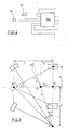
- Fig. 5 the conditions are shown in a four-wheel counterbalance truck.
- the steering axle is pendulum suspended in P.
- the wheelbase is y and the track b.
- the center of gravity S is located on the vehicle longitudinal axis at the height h and at a distance y F from the drive axle.
- the vehicle speed v is defined as the speed of the drive axle center M.
- the steered wheels of the rear axle are turned so that the vehicle turns around a point R. It lies at a distance r from the drive axle center point M.
- the stacker initially tilts over a tilting edge, which is formed by a connecting line between front wheel L and pendulum point P.
- the known in electric counterbalance trucks tilt prevention in which the vehicle speed is limited so that at the measured steering angle, the lateral acceleration remains below a predetermined value, is not readily applicable to counterbalanced forklift with an internal combustion engine with a hydrodynamic torque converter.
- the driver operates the driving function either via a Bowden cable or an electronic control. It lacks an actuator that limits the power output of the internal combustion engine, so as to limit the driving speed.
- the torque converter has a freewheeling function, so that no significant braking torque can be applied via the internal combustion engine.
- Another problem is the choice of a suitable sensor for determining the permissible driving speed.
- a speed sensor In regulated electric motor drives, as currently used, a speed sensor is already present. About the gear ratio and the wheel radius of the drive wheel, the driving speed can be determined. In a torque converter, the relationship between engine speed and vehicle speed is heavily load dependent. Older vehicles lack a speed sensor.
- the invention has for its object to provide a method and apparatus for tilting prevention of a counterbalance truck with an internal combustion engine, which can be effectively used by simple means.
- a characteristic for a tilt prevention is stored as a function of the driving speed from the steering angle. If the above-mentioned last formula is resolved according to the speed v and represented as a function of the steering angle ⁇ , a curve v ( ⁇ ) is obtained as the tilting limit. This is in Fig. 6 shown in a diagram.
- the characteristic stored in the control device which is located below the tipping limit, is naturally below the tipping limit and possibly includes dynamic reserves.
- the driving speed and the steering angle are measured or determined and from this the permissible driving speed is determined, namely from the mentioned characteristic. If the measured or determined driving speed or the specific speed exceeds the permissible value, two measures take place. On the one hand, the performance of the internal combustion engine is reduced. This is done by limiting the setpoint and / or by switching a power shift transmission in the neutral position. It is understood that the latter measure can only take place when a power shift transmission is arranged in the drive train. On the other hand, there is a deceleration, wherein the braking force is generated by driving a service brake and / or control of a counter-torque generator in the drive train and / or by switching the reverse gear in a power shift transmission.
- a counter-torque generator may e.g. be driven by a drive train hydraulic pump, which works on a hydraulic resistance.
- An alternative solution of the object according to the invention is to store in a control device, depending on the steering angle, maximum values for the lateral acceleration of the vehicle. While driving, the lateral acceleration is measured. In the control device, the lateral acceleration is compared with the respective maximum value. Exceeds the determined lateral acceleration the maximum value, the same measures are set in motion, as have been explained in connection with claim 1.
- the invention provides with simple measures that there is no risk of tipping when cornering counterbalance trucks. It is understood that the method steps prescribed by the method according to the invention are constantly repeated in order to counteract changing driving conditions.
- the steering angle and the driving speed must be measured.
- the steering angle may e.g. be measured by means of a steering angle sensor.
- the driving speed may e.g. be determined by the output speed of the transmission and the diameter of the driven wheels.
- the measurement of the driving speed is also conceivable via measurement of the engine speed and the engine load.
- the measure of the torque may e.g. be determined by known methods, such as measurement of the pressure or injection quantity.
- the driving speed can be estimated via the characteristic curve of the converter. For electronically controlled engines, both information is often available.
- the speed of both drive wheels can be measured. From the average and the wheel radius, the driving speed is determined. From the speed ratio of the steering angle can be determined and thus dispense with the steering angle sensor.
- the power reduction of the internal combustion engine can be done in different ways. If an electronically controlled combustion engine is available, the setpoint can be reduced via this. If a power shift transmission is set in the neutral position, This also leads to a reduction in performance. If the setpoint generator for the internal combustion engine mechanically works on an actuator of the internal combustion engine, a mechanical limitation can be made, for example, by the traction cable between accelerator pedal and actuator is extended. A comparable possibility results, for example, by an extension of the linkage between accelerator pedal and actuator of the internal combustion engine.
- Counterbalance trucks naturally have a service brake. This can be controlled by the control device according to the invention, if there is a risk of tipping.
- An alternative or additional possibility is a metered connection of the reverse gear in the presence of the power shift transmission in the drive train.
- a hydraulic pump may be driven by the drive train, which operates on a controllable hydraulic resistance, such as a controllable throttle to generate a counter-torque, resulting in a deceleration of the drive torque.
- the brake means used can generate a preset braking force. It is understood that the braking force can also be chosen differently high depending on the extent of the hazard, i. E. according to the extent of exceeding the permissible driving speed. It is further understood that for this purpose a brake controller can be used, which ensures that the desired braking value is achieved or maintained when driving the braking device.
- the risk of tipping is naturally influenced by the load taken and the height of the load on the counterbalance truck. Therefore, in one embodiment of the invention, it is provided to determine the height and the size of the load by means of corresponding sensors and to send a corresponding signal to the control device which thereby modifies the permissible value or the respectively measured speed value.
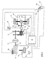
- Fig. 1 shows an internal combustion engine 10, such as a diesel or LPG engine, a torque converter 12, a power shift transmission 13 and a drive axle 14 with a differential 16 as the drive train of a counterbalance truck.
- Wheel brakes 18, 20 belong to front wheels 22, 24 of not shown Counterbalance truck. From this a rear steerable wheel 26 is shown for the steering axle.
- a hydraulic pump 28 is arranged, which operates on a controllable hydraulic throttle 30.
- On the drive axle 14 also sits another brake 32nd
- An accelerator pedal 34 acts on a control device 36, which controls the entire drive shown.
- Indicated at 38 is an actuator for the internal combustion engine 10, e.g. via a linkage or a traction cable (Bowden cable) adjusts the control variables of the internal combustion engine 10 or via an electronic control.
- the actuator 38 is also connected to the control device 36.
- a steering angle sensor 40 measures the steering angle of the steered wheel and provides a signal to the controller as well as a speed sensor 42 at the output of the engine 10, a speed sensor 44 on the output axle of the transmission 13, and speed sensors 46, 48 on the drive axle.
- the counterbalance truck naturally has a height-adjustable load-carrying device, which at 50 in Fig. 1 is shown. He is assigned a load sensor 52. For Hubtownnyak another sensor 54 is provided. The sensors 52, 54 are also connected to the central control device 36.
- a characteristic is stored, which in Fig. 6 is specified with "characteristic with dynamic reserves". It is located below the curve for the tilt limit during stationary cornering of the counterbalance truck.
- the tilting limit results from the calculations made above and it is understood that the driving condition must be chosen so that the tilting limit is not reached to prevent tilting.
- the individual sensors it is possible to determine the driving speed of the vehicle at any time. It is understood that not all speed sensors 42, 44, 46 or 48 are required. Via the drive axle 14, the speed can be determined when the radius of the driven wheels 22, 24 is known. The wheels may alternatively be assigned a respective speed sensor 46, 48. For this purpose, it is necessary to determine the speed values if the vehicle speed is to be determined during cornering.
- the driving speed is usually set by the pedal 34, and the actuator 38 adjusts the engine 10 so that the requirement of the setpoint generator is met. Now occurs at a measured steering angle via steering angle sensor 40 and a measured driving speed on a critical value, i. a value above the "dynamic reserve characteristic", appropriate countermeasures must be taken.
- the controller 36 modifies the setpoint and applies a reduced setpoint to the actuator 38.
- the power shift transmission 13 is switched to neutral position, also via the control device 36.
- a braking process is initiated.
- a braking option is to control the service brakes 18, 20 and 32 accordingly.
- Another possibility, additionally or alternatively, is to control the reverse gear in the manual transmission via the control device 36 in part.
- the hydraulic pump 28 which acts on the hydraulic throttle 30, a counter-torque can be generated on the drive axle 14, this counter-torque being adjustable in height via the control device 36.
- Fig. 2 an alternative solution with regard to the control of the control device 36 is shown.
- Their interconnection with regard to the components of the counterbalanced truck Fig. 1 resembles the Fig. 1
- a lateral accelerometer 56 is provided and in the control device 36 a steering angle dependent maximum values for the lateral acceleration are stored, which should not be exceeded during cornering. If this is the case, the measures will be taken individually or in combination, as in connection with Fig. 1 have been explained.
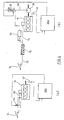
- Fig. 3 the three possibilities of modifying the speed setpoint of the internal combustion engine 10 are shown side by side.
- Fig. 3a the same drive of the actuator 38 is shown as in FIG Fig. 1
- Fig. 3b a separate engine control unit 60 is provided, which acts on the actuator 38 and to which the signal of the speed sensor 42 is given.
- the central control device 36b outputs in accordance with the measured values and the characteristic as described in connection with FIG Fig. 1 has been explained, the modified setpoint for the internal combustion engine 10, and the controller 16 downshifts the speed to the desired value.
- the pedal 34 acts directly on the engine control unit 60a, wherein in the control device 36c, in turn, the setpoint value for the internal combustion engine 10 is given modified to the control unit 60a in order to change the value predetermined by the pedal 34.
- FIGS. 4a and 4b there is a mechanical connection between the accelerator pedal 34 and the actuator on the internal combustion engine 10.
- Fig. 4a is a drawbar or Wegseilitati 62 indicated, which is variable by action on the control device 36 at 64 in length. If the setpoint, which is predetermined by the pedal 34, to be reduced, this is done by an extension of the drive connection, whereby the internal combustion engine 10 is set to a low speed.
Landscapes
- Engineering & Computer Science (AREA)
- Structural Engineering (AREA)
- Transportation (AREA)
- Life Sciences & Earth Sciences (AREA)
- Geology (AREA)
- Mechanical Engineering (AREA)
- Civil Engineering (AREA)
- Control Of Vehicle Engines Or Engines For Specific Uses (AREA)
- Forklifts And Lifting Vehicles (AREA)
- Control Of Transmission Device (AREA)
Applications Claiming Priority (1)
| Application Number | Priority Date | Filing Date | Title |
|---|---|---|---|
| DE200710019506 DE102007019506A1 (de) | 2007-04-25 | 2007-04-25 | Verfahren und Vorrichtung zur Kippvermeidung eines Gegengewichtsstaplers |
Publications (3)
| Publication Number | Publication Date |
|---|---|
| EP1985576A2 true EP1985576A2 (fr) | 2008-10-29 |
| EP1985576A3 EP1985576A3 (fr) | 2010-06-16 |
| EP1985576B1 EP1985576B1 (fr) | 2015-08-26 |
Family
ID=39708667
Family Applications (1)
| Application Number | Title | Priority Date | Filing Date |
|---|---|---|---|
| EP08002794.9A Not-in-force EP1985576B1 (fr) | 2007-04-25 | 2008-02-15 | Procédé et dispositif destinés à empêcher le basculement d'un dispositif d'empilage à contrepoids |
Country Status (2)
| Country | Link |
|---|---|
| EP (1) | EP1985576B1 (fr) |
| DE (1) | DE102007019506A1 (fr) |
Cited By (15)
| Publication number | Priority date | Publication date | Assignee | Title |
|---|---|---|---|---|
| EP2172414A1 (fr) * | 2008-10-01 | 2010-04-07 | Still Sas | Chariot de manutention commandé par timon |
| EP2409887A3 (fr) * | 2010-07-19 | 2013-08-28 | Noell Mobile Systems GmbH | Procédé et système de régulation de la tenue de route d'un véhicule utilitaire |
| EP2674387A1 (fr) | 2012-06-12 | 2013-12-18 | Atlet AB | Camion industriel avec contrôle d'angle amélioré |
| CN103675320A (zh) * | 2013-12-13 | 2014-03-26 | 中联重科股份有限公司 | 压路机最大转向速度检测方法、防侧翻控制方法及设备 |
| EP2733036A3 (fr) * | 2012-11-16 | 2018-05-02 | Kramer-Werke GmbH | Machine mobile comprenant une installation de chargement |
| EP3330145A1 (fr) * | 2016-11-30 | 2018-06-06 | Jungheinrich Aktiengesellschaft | Chariot de manutention doté d'une commande de freinage |
| CN109531585A (zh) * | 2017-09-22 | 2019-03-29 | 松下知识产权经营株式会社 | 机器人 |
| US10452080B1 (en) | 2018-05-21 | 2019-10-22 | International Business Machines Corporation | Self-actuating device for facilitating preventing product tip over |
| US10743666B2 (en) | 2018-09-21 | 2020-08-18 | International Business Machines Corporation | Self-acting device for facilitating preventing product tip over |
| DE102021211708A1 (de) | 2021-10-18 | 2023-04-20 | Zf Friedrichshafen Ag | Verfahren zur Beschränkung des Fahrverhaltens eines motorgetriebenen Flurförderzeugs, Steuereinrichtung dafür und motorgetriebenes Flurförderzug |
| DE102022107761A1 (de) | 2022-04-01 | 2023-10-05 | Hamm Ag | Verfahren zum Betreiben einer Bodenbearbeitungsmaschine |
| US11827503B2 (en) | 2020-03-18 | 2023-11-28 | Crown Equipment Corporation | Adaptive acceleration for materials handling vehicle |
| EP4389683A1 (fr) | 2022-12-23 | 2024-06-26 | Manitou Bf | Engin de manutention de charge |
| US12066844B2 (en) | 2020-11-03 | 2024-08-20 | Crown Equipment Corporation | Adaptive acceleration for materials handling vehicle |
| US12259724B2 (en) | 2019-08-27 | 2025-03-25 | Crown Equipment Corporation | Adaptive acceleration for materials handling vehicle |
Families Citing this family (3)
| Publication number | Priority date | Publication date | Assignee | Title |
|---|---|---|---|---|
| DE102011080805B4 (de) | 2011-08-11 | 2020-03-26 | Robert Bosch Gmbh | Verfahren und Vorrichtung zum Betreiben einer Hubeinrichtung |
| DE102016205491A1 (de) * | 2016-04-04 | 2017-10-05 | Zf Friedrichshafen Ag | Getriebeanordnung zum Antrieb eines Kraftfahrzeugs |
| CN112193338B (zh) * | 2020-10-10 | 2022-03-22 | 伊威智能科技(常州)有限公司 | 一种可装卸重心偏移自调节的防倾倒智能叉车 |
Citations (10)
| Publication number | Priority date | Publication date | Assignee | Title |
|---|---|---|---|---|
| DE2909667C2 (de) | 1979-03-12 | 1985-02-14 | Jungheinrich Unternehmensverwaltung Kg, 2000 Hamburg | Elektrischer Antriebs-Steuerteil für lenkbare Fahrzeuge, insbesondere Hublader |
| DE19919655A1 (de) | 1999-04-29 | 2000-11-09 | Jungheinrich Ag | Flurförderzeug mit Kippsicherung |
| DE19918597A1 (de) | 1999-04-23 | 2000-11-23 | Deutsch Zentr Luft & Raumfahrt | Verfahren zur Reduktion der Kippgefahr von Straßenfahrzeugen |
| EP1475297A1 (fr) | 2003-05-08 | 2004-11-10 | Bt Industries Ab | Dispositif de sécurité pour un chariot mené par un conducteur marchant |
| DE102004028053A1 (de) | 2004-06-09 | 2005-12-29 | Still Gmbh | Verfahren und Vorrichtung zur Kippvermeidung eines Flurförderzeugs |
| DE102004035888A1 (de) | 2004-07-23 | 2006-03-16 | Bayerische Motoren Werke Ag | Verfahren zur Reduktion der Kippgefahr eines zweispurigen Straßenfahrzeugs |
| DE102004046890A1 (de) | 2004-09-28 | 2006-03-30 | Jungheinrich Ag | Verfahren zur Kippvermeidung von hinterradgelenkten Fahrzeugen, insbesondere Flurförderzeugen |
| DE20023781U1 (de) | 2000-07-20 | 2006-06-14 | Frie, Werner, Dr. | Vorrichtung zur Fahrdynamikregelung |
| DE10035180B4 (de) | 2000-07-20 | 2006-07-06 | Frie, Werner, Dr. | Verfahren und Vorrichtung zur Fahrdynamikregelung |
| DE102005015673A1 (de) | 2005-04-06 | 2006-10-12 | Jungheinrich Ag | Lenksystem für ein Flurförderzeug |
Family Cites Families (8)
| Publication number | Priority date | Publication date | Assignee | Title |
|---|---|---|---|---|
| DE2651594A1 (de) * | 1976-11-12 | 1978-05-24 | Bengel Friedrich | Gabelstapler |
| US4942529A (en) * | 1988-05-26 | 1990-07-17 | The Raymond Corporation | Lift truck control systems |
| DE19830190A1 (de) * | 1998-04-18 | 1999-10-21 | Continental Teves Ag & Co Ohg | Verfahren und Vorrichtung zur Begrenzung der Querbeschleunigung eines fahrenden Fahrzeugs |
| US6494281B1 (en) * | 1998-04-07 | 2002-12-17 | Robert Bosch Gmbh | Method and device for stabilizing a vehicle |
| DE10010011A1 (de) * | 1999-07-27 | 2001-02-01 | Linde Ag | Flurförderzeug mit einer Stabilisierungseinrichtung zur Erhöhung der Standsicherheit |
| DE10128357A1 (de) * | 2001-06-13 | 2003-03-06 | Continental Teves Ag & Co Ohg | Verfahren zur Regelung der Fahrstabilität |
| DE102005012004B4 (de) * | 2004-04-07 | 2020-09-24 | Linde Material Handling Gmbh | Flurförderzeug mit erhöhter statischer/quasistatischer und dynamischer Kippstabilität |
| JP4807028B2 (ja) * | 2005-09-30 | 2011-11-02 | 株式会社豊田自動織機 | フォークリフトの走行制御装置 |
-
2007
- 2007-04-25 DE DE200710019506 patent/DE102007019506A1/de not_active Withdrawn
-
2008
- 2008-02-15 EP EP08002794.9A patent/EP1985576B1/fr not_active Not-in-force
Patent Citations (10)
| Publication number | Priority date | Publication date | Assignee | Title |
|---|---|---|---|---|
| DE2909667C2 (de) | 1979-03-12 | 1985-02-14 | Jungheinrich Unternehmensverwaltung Kg, 2000 Hamburg | Elektrischer Antriebs-Steuerteil für lenkbare Fahrzeuge, insbesondere Hublader |
| DE19918597A1 (de) | 1999-04-23 | 2000-11-23 | Deutsch Zentr Luft & Raumfahrt | Verfahren zur Reduktion der Kippgefahr von Straßenfahrzeugen |
| DE19919655A1 (de) | 1999-04-29 | 2000-11-09 | Jungheinrich Ag | Flurförderzeug mit Kippsicherung |
| DE20023781U1 (de) | 2000-07-20 | 2006-06-14 | Frie, Werner, Dr. | Vorrichtung zur Fahrdynamikregelung |
| DE10035180B4 (de) | 2000-07-20 | 2006-07-06 | Frie, Werner, Dr. | Verfahren und Vorrichtung zur Fahrdynamikregelung |
| EP1475297A1 (fr) | 2003-05-08 | 2004-11-10 | Bt Industries Ab | Dispositif de sécurité pour un chariot mené par un conducteur marchant |
| DE102004028053A1 (de) | 2004-06-09 | 2005-12-29 | Still Gmbh | Verfahren und Vorrichtung zur Kippvermeidung eines Flurförderzeugs |
| DE102004035888A1 (de) | 2004-07-23 | 2006-03-16 | Bayerische Motoren Werke Ag | Verfahren zur Reduktion der Kippgefahr eines zweispurigen Straßenfahrzeugs |
| DE102004046890A1 (de) | 2004-09-28 | 2006-03-30 | Jungheinrich Ag | Verfahren zur Kippvermeidung von hinterradgelenkten Fahrzeugen, insbesondere Flurförderzeugen |
| DE102005015673A1 (de) | 2005-04-06 | 2006-10-12 | Jungheinrich Ag | Lenksystem für ein Flurförderzeug |
Cited By (21)
| Publication number | Priority date | Publication date | Assignee | Title |
|---|---|---|---|---|
| EP2172414A1 (fr) * | 2008-10-01 | 2010-04-07 | Still Sas | Chariot de manutention commandé par timon |
| EP2409887A3 (fr) * | 2010-07-19 | 2013-08-28 | Noell Mobile Systems GmbH | Procédé et système de régulation de la tenue de route d'un véhicule utilitaire |
| EP2674387A1 (fr) | 2012-06-12 | 2013-12-18 | Atlet AB | Camion industriel avec contrôle d'angle amélioré |
| EP2733036A3 (fr) * | 2012-11-16 | 2018-05-02 | Kramer-Werke GmbH | Machine mobile comprenant une installation de chargement |
| CN103675320A (zh) * | 2013-12-13 | 2014-03-26 | 中联重科股份有限公司 | 压路机最大转向速度检测方法、防侧翻控制方法及设备 |
| EP3330145A1 (fr) * | 2016-11-30 | 2018-06-06 | Jungheinrich Aktiengesellschaft | Chariot de manutention doté d'une commande de freinage |
| CN109531585A (zh) * | 2017-09-22 | 2019-03-29 | 松下知识产权经营株式会社 | 机器人 |
| US10768640B2 (en) | 2018-05-21 | 2020-09-08 | International Business Machines Corporation | Self-actuating device for facilitating preventing product tip over |
| US10452080B1 (en) | 2018-05-21 | 2019-10-22 | International Business Machines Corporation | Self-actuating device for facilitating preventing product tip over |
| US10606284B2 (en) | 2018-05-21 | 2020-03-31 | International Business Machines Corporation | Self-actuating device for facilitating preventing product tip over |
| US10743666B2 (en) | 2018-09-21 | 2020-08-18 | International Business Machines Corporation | Self-acting device for facilitating preventing product tip over |
| US12259724B2 (en) | 2019-08-27 | 2025-03-25 | Crown Equipment Corporation | Adaptive acceleration for materials handling vehicle |
| US11919761B2 (en) | 2020-03-18 | 2024-03-05 | Crown Equipment Corporation | Based on detected start of picking operation, resetting stored data related to monitored drive parameter |
| US11827503B2 (en) | 2020-03-18 | 2023-11-28 | Crown Equipment Corporation | Adaptive acceleration for materials handling vehicle |
| US12066844B2 (en) | 2020-11-03 | 2024-08-20 | Crown Equipment Corporation | Adaptive acceleration for materials handling vehicle |
| US12411505B2 (en) | 2020-11-03 | 2025-09-09 | Crown Equipment Corporation | Adaptive acceleration for materials handling vehicle |
| DE102021211708A1 (de) | 2021-10-18 | 2023-04-20 | Zf Friedrichshafen Ag | Verfahren zur Beschränkung des Fahrverhaltens eines motorgetriebenen Flurförderzeugs, Steuereinrichtung dafür und motorgetriebenes Flurförderzug |
| DE102022107761A1 (de) | 2022-04-01 | 2023-10-05 | Hamm Ag | Verfahren zum Betreiben einer Bodenbearbeitungsmaschine |
| US12473026B2 (en) | 2022-04-01 | 2025-11-18 | Hamm Ag | Method for operating a soil processing machine |
| EP4389683A1 (fr) | 2022-12-23 | 2024-06-26 | Manitou Bf | Engin de manutention de charge |
| FR3144125A1 (fr) * | 2022-12-23 | 2024-06-28 | Manitou Bf | Engin de manutention de charge |
Also Published As
| Publication number | Publication date |
|---|---|
| EP1985576A3 (fr) | 2010-06-16 |
| DE102007019506A1 (de) | 2008-10-30 |
| EP1985576B1 (fr) | 2015-08-26 |
Similar Documents
| Publication | Publication Date | Title |
|---|---|---|
| EP1985576B1 (fr) | Procédé et dispositif destinés à empêcher le basculement d'un dispositif d'empilage à contrepoids | |
| EP0606345B1 (fr) | Systeme d'entrainement d'un vehicule a moteur | |
| DE102005011613B4 (de) | Regelungssystem für ein brems-lenk-assistiertes Parken und ein Verfahren dafür | |
| EP1919728B1 (fr) | Systeme de controle d'adherence en descente pour un vehicule a moteur | |
| EP0607226B1 (fr) | Direction assistee pour vehicules non relies a des rails | |
| DE10200783C2 (de) | Anfahrhilfesteuerungsvorrichtung | |
| EP2512886B1 (fr) | Procédé et système de freinage permettant d'influer sur le comportement dynamique en intervenant sur le freinage et l'entraînement | |
| DE19831071C2 (de) | Lenksystem für Kraftfahrzeuge | |
| WO2008037347A1 (fr) | Système de freinage et méthode de freinage d'un véhicule à propulsion hybride | |
| EP2487079B1 (fr) | Procédé de fonctionnement d'un véhicule automobile lors du passage d'un virage | |
| EP2013069A1 (fr) | Procédé et dispositif de détermination d'un angle de braquage optimal lors de situations de sous-virage d'un véhicule | |
| DE102007007127A1 (de) | Differenzialbeschränkungssteuergerät für ein Fahrzeug | |
| EP0140208B1 (fr) | Dispositif pour limiter ou empêcher le patinage des roues motrices d'un camion | |
| EP0318857A1 (fr) | Dispositif de réglage du moment du moteur à combustion interne d'un véhicule automobile | |
| DE102014202230A1 (de) | Verfahren und Vorrichtung zum Verhindern eines Kippens eines lenkbaren Fahrzeugs | |
| EP1045783B1 (fr) | Dispositif et procede pour limiter la vitesse de roulement en arriere d'un vehicule automobile | |
| DE10332023A1 (de) | Verfahren zum Bestimmen eines Lenkmoments für eine Lenkung eines Fahrzeugs | |
| EP2072364B1 (fr) | Dispositif destiné à la prise en charge semi-automatique d'un processus de stationnement d'un véhicule | |
| EP2733036B1 (fr) | Machine mobile comprenant une installation de chargement | |
| DE10008984B4 (de) | Lenksystem für ein Flurförderzeug | |
| EP0962369A2 (fr) | Dispositif pour générer une pression de freinage au moyen d' une pompe | |
| EP1826082B1 (fr) | Système de réglage de patinage et procédé destiné au réglage de mouvements de roues d'un véhicule | |
| DE10250764B3 (de) | Verfahren und Vorrichtung zur Lenkung eines Flurförderzeuges | |
| EP3214035B1 (fr) | Procédé de fonctionnement d'un chariot de manutention | |
| WO2024132400A1 (fr) | Procédé de détermination d'un écart de performance entre une performance cible et une performance réelle d'un actionneur de véhicule |
Legal Events
| Date | Code | Title | Description |
|---|---|---|---|
| PUAI | Public reference made under article 153(3) epc to a published international application that has entered the european phase |
Free format text: ORIGINAL CODE: 0009012 |
|
| AK | Designated contracting states |
Kind code of ref document: A2 Designated state(s): AT BE BG CH CY CZ DE DK EE ES FI FR GB GR HR HU IE IS IT LI LT LU LV MC MT NL NO PL PT RO SE SI SK TR |
|
| AX | Request for extension of the european patent |
Extension state: AL BA MK RS |
|
| PUAL | Search report despatched |
Free format text: ORIGINAL CODE: 0009013 |
|
| AK | Designated contracting states |
Kind code of ref document: A3 Designated state(s): AT BE BG CH CY CZ DE DK EE ES FI FR GB GR HR HU IE IS IT LI LT LU LV MC MT NL NO PL PT RO SE SI SK TR |
|
| AX | Request for extension of the european patent |
Extension state: AL BA MK RS |
|
| 17P | Request for examination filed |
Effective date: 20101126 |
|
| AKX | Designation fees paid |
Designated state(s): DE FR GB IT |
|
| 17Q | First examination report despatched |
Effective date: 20121011 |
|
| GRAP | Despatch of communication of intention to grant a patent |
Free format text: ORIGINAL CODE: EPIDOSNIGR1 |
|
| INTG | Intention to grant announced |
Effective date: 20150423 |
|
| GRAS | Grant fee paid |
Free format text: ORIGINAL CODE: EPIDOSNIGR3 |
|
| GRAA | (expected) grant |
Free format text: ORIGINAL CODE: 0009210 |
|
| AK | Designated contracting states |
Kind code of ref document: B1 Designated state(s): DE FR GB IT |
|
| REG | Reference to a national code |
Ref country code: GB Ref legal event code: FG4D Free format text: NOT ENGLISH |
|
| REG | Reference to a national code |
Ref country code: DE Ref legal event code: R096 Ref document number: 502008013298 Country of ref document: DE |
|
| REG | Reference to a national code |
Ref country code: FR Ref legal event code: PLFP Year of fee payment: 9 |
|
| REG | Reference to a national code |
Ref country code: DE Ref legal event code: R097 Ref document number: 502008013298 Country of ref document: DE |
|
| PLBE | No opposition filed within time limit |
Free format text: ORIGINAL CODE: 0009261 |
|
| STAA | Information on the status of an ep patent application or granted ep patent |
Free format text: STATUS: NO OPPOSITION FILED WITHIN TIME LIMIT |
|
| 26N | No opposition filed |
Effective date: 20160530 |
|
| REG | Reference to a national code |
Ref country code: FR Ref legal event code: PLFP Year of fee payment: 10 |
|
| PGFP | Annual fee paid to national office [announced via postgrant information from national office to epo] |
Ref country code: FR Payment date: 20170224 Year of fee payment: 10 |
|
| PGFP | Annual fee paid to national office [announced via postgrant information from national office to epo] |
Ref country code: GB Payment date: 20170228 Year of fee payment: 10 |
|
| PGFP | Annual fee paid to national office [announced via postgrant information from national office to epo] |
Ref country code: IT Payment date: 20170221 Year of fee payment: 10 |
|
| GBPC | Gb: european patent ceased through non-payment of renewal fee |
Effective date: 20180215 |
|
| REG | Reference to a national code |
Ref country code: FR Ref legal event code: ST Effective date: 20181031 |
|
| PG25 | Lapsed in a contracting state [announced via postgrant information from national office to epo] |
Ref country code: IT Free format text: LAPSE BECAUSE OF NON-PAYMENT OF DUE FEES Effective date: 20180215 Ref country code: GB Free format text: LAPSE BECAUSE OF NON-PAYMENT OF DUE FEES Effective date: 20180215 Ref country code: FR Free format text: LAPSE BECAUSE OF NON-PAYMENT OF DUE FEES Effective date: 20180228 |
|
| PGFP | Annual fee paid to national office [announced via postgrant information from national office to epo] |
Ref country code: DE Payment date: 20200429 Year of fee payment: 13 |
|
| REG | Reference to a national code |
Ref country code: DE Ref legal event code: R119 Ref document number: 502008013298 Country of ref document: DE |
|
| PG25 | Lapsed in a contracting state [announced via postgrant information from national office to epo] |
Ref country code: DE Free format text: LAPSE BECAUSE OF NON-PAYMENT OF DUE FEES Effective date: 20210901 |