EP1985770A2 - Procédé de réalisation d'une fixation d'éléments de construction à du béton - Google Patents
Procédé de réalisation d'une fixation d'éléments de construction à du béton Download PDFInfo
- Publication number
- EP1985770A2 EP1985770A2 EP08007166A EP08007166A EP1985770A2 EP 1985770 A2 EP1985770 A2 EP 1985770A2 EP 08007166 A EP08007166 A EP 08007166A EP 08007166 A EP08007166 A EP 08007166A EP 1985770 A2 EP1985770 A2 EP 1985770A2
- Authority
- EP
- European Patent Office
- Prior art keywords
- concrete
- wire body
- insert body
- rod
- mounting bracket
- Prior art date
- Legal status (The legal status is an assumption and is not a legal conclusion. Google has not performed a legal analysis and makes no representation as to the accuracy of the status listed.)
- Withdrawn
Links
Images




Classifications
-
- E—FIXED CONSTRUCTIONS
- E04—BUILDING
- E04B—GENERAL BUILDING CONSTRUCTIONS; WALLS, e.g. PARTITIONS; ROOFS; FLOORS; CEILINGS; INSULATION OR OTHER PROTECTION OF BUILDINGS
- E04B1/00—Constructions in general; Structures which are not restricted either to walls, e.g. partitions, or floors or ceilings or roofs
- E04B1/38—Connections for building structures in general
- E04B1/41—Connecting devices specially adapted for embedding in concrete or masonry
- E04B1/4114—Elements with sockets
- E04B1/4121—Elements with sockets with internal threads or non-adjustable captive nuts
-
- B—PERFORMING OPERATIONS; TRANSPORTING
- B25—HAND TOOLS; PORTABLE POWER-DRIVEN TOOLS; MANIPULATORS
- B25B—TOOLS OR BENCH DEVICES NOT OTHERWISE PROVIDED FOR, FOR FASTENING, CONNECTING, DISENGAGING, OR HOLDING
- B25B27/00—Hand tools, specially adapted for fitting together or separating parts or objects whether or not involving some deformation, not otherwise provided for
- B25B27/14—Hand tools, specially adapted for fitting together or separating parts or objects whether or not involving some deformation, not otherwise provided for for assembling objects other than by press fit or detaching same
- B25B27/143—Hand tools, specially adapted for fitting together or separating parts or objects whether or not involving some deformation, not otherwise provided for for assembling objects other than by press fit or detaching same for installing wire thread inserts or tubular threaded inserts
-
- F—MECHANICAL ENGINEERING; LIGHTING; HEATING; WEAPONS; BLASTING
- F16—ENGINEERING ELEMENTS AND UNITS; GENERAL MEASURES FOR PRODUCING AND MAINTAINING EFFECTIVE FUNCTIONING OF MACHINES OR INSTALLATIONS; THERMAL INSULATION IN GENERAL
- F16B—DEVICES FOR FASTENING OR SECURING CONSTRUCTIONAL ELEMENTS OR MACHINE PARTS TOGETHER, e.g. NAILS, BOLTS, CIRCLIPS, CLAMPS, CLIPS OR WEDGES; JOINTS OR JOINTING
- F16B37/00—Nuts or like thread-engaging members
- F16B37/12—Nuts or like thread-engaging members with thread-engaging surfaces formed by inserted coil-springs, discs, or the like; Independent pieces of wound wire used as nuts; Threaded inserts for holes
Definitions
- the invention relates to a method for producing a fastening of components to concrete, so for example on construction sites of columns on prefabricated concrete slabs, in which in the concrete a helical wire body is used, which forms an internal thread for receiving a provided with an external threaded fastener.
- the anchor rod is characterized by a thread that an inserted wire body whose last turns to the free end tapered when screwing the fastener is spread by the force applied thereby , This adhesion depends very much on the precise coordination of the dimensions of the fastener and the wire body from each other and requires the construction of a complicated and precise assembly of the individual parts.
- the invention has for its object to provide a method of the type mentioned and suitable means that are simpler.
- This object is achieved in that the helical wire body is held by a support rod, that the support rod removed after curing of the concrete and the fastener is screwed.
- the invention further comprises advantageous developments.
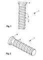
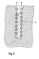
- FIGS. 1 and 2 show a substantially cylindrical holding bar 1 made of foamed plastic (for example Styrofoam) with a length of about 110 and a diameter of about 20 mm. It is - similar to a screw - with a helical, in cross-section approximately semicircular circumferential groove 2 provided.
- foamed plastic for example Styrofoam
- the holding bar 1 is surrounded on its cylindrical outer side by a helical wire body 3, which fits into the groove 2.
- the wire body 3 has the shape of a spring, although the spring properties in the present context are not important.
- the wire from which the wire body 3 is bent has a diameter of about 2 - 5 mm, wherein the individual turns from each other may have a distance of about 2-10 mm.
- the wire body 3 is about 100 mm long. With its half cross section, the wire protrudes beyond the cylindrical outer surface 1 'of the retaining bar 1.
- the upper end 4 of the retaining bar 1 is used for handling. Holding rod 1 and wire body 3 form an insert body 20.
- the retaining bar 1 separately - with groove 2 - foam, holding rod and wire body manufacture and deliver separately, so that the user then the holding rod in the Turns in the wire body before inserting the insert body into the concrete or attaching it to the reinforcement.
- the insert body 20 it is also possible to produce the insert body 20 such that the holding bar 1 is foamed in a mold into which the wire body 3 has already been inserted.
- the insert body 20 is when concreting, for example, a concrete slab at the point from which it is known that thereafter in the course of a mounting another component to be attached, inserted into the still liquid concrete, as in FIG. 4 is shown.
- the upper end 4 of the support bar 1 is pressed so far into the concrete that it subsequently flush with the upper boundary surface 5 of the concrete body 6, so that you can see after curing of the concrete, where is the support rod.
- the holding rod 1 made of foamed plastic is removed from this composite. If the retaining bar 1 is partially glued to the concrete and therefore can not be easily unscrewed, it will be removed by drilling with a drill whose diameter should be slightly less than the inside diameter of the wire body 3. This can easily be done with a cordless screwdriver. That not all parts of the existing plastic foam holding rod 1 are removed, but possibly some crumbs remain in the resulting cavity 7, is not a hindrance to further use.
- the resulting by removal of the retaining rod 1 cavity 7 is in section in FIG. 5 shown.
- the retaining bar 1 thus has the function of a body made of polystyrene, which can subsequently be removed in a simple manner for the insert body 20.
- the only part of his Cross-section in the outer wall integrated wire body 3 now has the function of an internal thread.
- a provided with the internal thread cavity 7 has arisen, in which a provided with a matching external thread - known per se - tension rod 9 can be screwed to form a fastener for another component, such as a formwork or a support ,
- tension rod 9 is a steel rod with a circumferential, forming an external thread bead 8.
- anchor is a steel rod with a circumferential, forming an external thread bead 8.
- This tension rod 9 is screwed into the internal thread formed by the wire body 3 and can be used for fastening a plate 11 using a nut 10, for example.
- FIG. 7 shows an alternative to the preparation of the provided with an internal thread in the form of an integrated wire body 3 cavity 7.
- a bore 12 is drilled in the already hardened concrete body 6, whose diameter is larger than the outer diameter of the insert body 20.
- the insert body 20 is used.
- a fast-curing anchor adhesive is commercially available, for example, under the name "Sika Ancor Fix” or “Sikadur” (see brochure of Sika GmbH, 72574 Bad Urach).
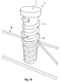
- FIG. 8 shows a mounting bracket 30 which is integrally bent from wire. Starting from its end 31, it has the shape of an elongated rectangular frame, which merges at the point 32 approximately in the middle of a longitudinal side of the frame in a trained as a spring wire body 33, which - in the embodiment - comprises about two and a half turns. Due to the frame-like design of the mounting bracket this can be placed on any surface.
- the wire body 33 then provides for the wire body 3 of an insert body 20 (FIG. FIG. 3 ) in turn is a thread into which the insert body 20 can be screwed and securely held in the concrete, such as when the mounting bracket 30 rests on a horizontally disposed formwork panel 50.
- FIG. 9 and 10 Such a situation is in the Figures 9 and 10 illustrated, wherein - for illustration - the two narrow side portions of the mounting bracket are mounted on pins 36.
- a mounting bracket 30 not only - as in FIG. 8 - Can be placed on a surface, so as a horizontally lying formwork panel 50 in which a concrete part is poured, but can be arranged with simple tools at a certain height on a formwork panel.
- FIG. 11 It can be seen how a structure consisting of mounting bracket 30 and insert body 20 can be fastened to a bar 35 of a reinforcement for a concrete slab.
- the attachment is by means of a piece of wire 40 which is wound around the wire forming the mounting bracket 30 and the rod 35. Since such reinforcements in turn by suitable spacers of the Base, which in turn can be formed, for example, by a formwork panel, are kept at a certain distance to this, a secure position of the insert body 20 is ensured in the desired position in this way.
- Insert body 20 and mounting bracket 30 can also be used vice versa on a formwork panel, so that the surface of the end 4 of the support rod 1 of the insert body 20 rests on the formwork panel 50 and, if this surface then forms the visible surface of the concrete part to be created, directly from this is accessible.
Landscapes
- Engineering & Computer Science (AREA)
- Architecture (AREA)
- Physics & Mathematics (AREA)
- Electromagnetism (AREA)
- Civil Engineering (AREA)
- Structural Engineering (AREA)
- Mechanical Engineering (AREA)
- Joining Of Building Structures In Genera (AREA)
Applications Claiming Priority (2)
| Application Number | Priority Date | Filing Date | Title |
|---|---|---|---|
| DE102007020320 | 2007-04-23 | ||
| DE102008014806A DE102008014806A1 (de) | 2007-04-23 | 2008-03-10 | Verfahren zur Herstellung einer Befestigung von Bauteilen an Beton |
Publications (2)
| Publication Number | Publication Date |
|---|---|
| EP1985770A2 true EP1985770A2 (fr) | 2008-10-29 |
| EP1985770A3 EP1985770A3 (fr) | 2010-12-15 |
Family
ID=39542993
Family Applications (1)
| Application Number | Title | Priority Date | Filing Date |
|---|---|---|---|
| EP08007166A Withdrawn EP1985770A3 (fr) | 2007-04-23 | 2008-04-11 | Procédé de réalisation d'une fixation d'éléments de construction à du béton |
Country Status (1)
| Country | Link |
|---|---|
| EP (1) | EP1985770A3 (fr) |
Cited By (3)
| Publication number | Priority date | Publication date | Assignee | Title |
|---|---|---|---|---|
| CN107100278A (zh) * | 2017-06-22 | 2017-08-29 | 绍兴明煌建材科技有限公司 | 一种混凝土预埋螺纹套及其使用方法 |
| CN111764507A (zh) * | 2020-06-05 | 2020-10-13 | 李华 | 一种后浇丝预制连接结构 |
| EP4613954A3 (fr) * | 2016-01-11 | 2025-11-05 | Pino Albanese | Douille filetée pour l'ancrage d'éléments de construction dans une construction en béton, et un tuyau d'écartement |
Citations (4)
| Publication number | Priority date | Publication date | Assignee | Title |
|---|---|---|---|---|
| DE78235C (de) | j. boeddinghaus, Düsseldorf, Stephanienstr. 17 | Befestigungsweise von mit Schraubenbolzen versehenen Haken und dergl. in der Wand | ||
| US1145462A (en) | 1912-11-11 | 1915-07-06 | Francis M Barton | Socket for concrete construction. |
| DE19547318A1 (de) | 1995-12-18 | 1997-06-19 | Manfred Hoffmann | Ankerstab zum Einleiten von Zug- und/oder Druckkräften in Baustoffe |
| DE20111550U1 (de) | 2001-07-13 | 2002-01-17 | Betomax Kunststoff- und Metallwarenfabrik GmbH & Co. KG, 41460 Neuss | Einbetonierbare Gewindehülse für Ankerstäbe |
Family Cites Families (2)
| Publication number | Priority date | Publication date | Assignee | Title |
|---|---|---|---|---|
| JPS57120746A (en) * | 1981-01-16 | 1982-07-27 | Nhk Spring Co Ltd | Coil spring device |
| FR2543481B1 (fr) * | 1983-03-31 | 1986-03-14 | Francis Laroche | Dispositif d'ancrage dans le beton |
-
2008
- 2008-04-11 EP EP08007166A patent/EP1985770A3/fr not_active Withdrawn
Patent Citations (4)
| Publication number | Priority date | Publication date | Assignee | Title |
|---|---|---|---|---|
| DE78235C (de) | j. boeddinghaus, Düsseldorf, Stephanienstr. 17 | Befestigungsweise von mit Schraubenbolzen versehenen Haken und dergl. in der Wand | ||
| US1145462A (en) | 1912-11-11 | 1915-07-06 | Francis M Barton | Socket for concrete construction. |
| DE19547318A1 (de) | 1995-12-18 | 1997-06-19 | Manfred Hoffmann | Ankerstab zum Einleiten von Zug- und/oder Druckkräften in Baustoffe |
| DE20111550U1 (de) | 2001-07-13 | 2002-01-17 | Betomax Kunststoff- und Metallwarenfabrik GmbH & Co. KG, 41460 Neuss | Einbetonierbare Gewindehülse für Ankerstäbe |
Cited By (3)
| Publication number | Priority date | Publication date | Assignee | Title |
|---|---|---|---|---|
| EP4613954A3 (fr) * | 2016-01-11 | 2025-11-05 | Pino Albanese | Douille filetée pour l'ancrage d'éléments de construction dans une construction en béton, et un tuyau d'écartement |
| CN107100278A (zh) * | 2017-06-22 | 2017-08-29 | 绍兴明煌建材科技有限公司 | 一种混凝土预埋螺纹套及其使用方法 |
| CN111764507A (zh) * | 2020-06-05 | 2020-10-13 | 李华 | 一种后浇丝预制连接结构 |
Also Published As
| Publication number | Publication date |
|---|---|
| EP1985770A3 (fr) | 2010-12-15 |
Similar Documents
| Publication | Publication Date | Title |
|---|---|---|
| EP2666919B1 (fr) | Procédé et système de fixation pour le montage de plaques d'isolant sur une surface de support | |
| DE2627524B2 (de) | Verpressanker | |
| DE102011078696A1 (de) | Anordnung aus Gewebehülse und Aushärtmaterial zum Befestigen eines Verankerungselements in einem Bohrloch | |
| DE3100730A1 (de) | Verfahren zum stuetzen und/oder verfestigen von hohlraumwaenden im tief-, berg- und tunnelbau, vorrichtung zum durchfuehren des verfahrens und in einem bohrloch der hohlraumwand sitzender verfestigungsanker | |
| EP2817465B1 (fr) | Dispositif d'introduction de force dans des éléments de traction à partir de lamelles de bandes plates en matière synthétique renforcées en fibres | |
| EP2606185B1 (fr) | Dispositif d'introduction de force dans des éléments de traction constitués de lamelles plates en matière plastique renforcée par des fibres | |
| EP2992226B1 (fr) | Système d'ancrage | |
| EP2853654A2 (fr) | Console et infrastructure de façade dotée d'une telle console | |
| EP2003270B1 (fr) | Système et procédé de fixation d'un objet en forme de mât ou de poteau dans le sol en terre avec une partie réceptrice en plusieurs pièces pouvant être vissées sur le sol en terre | |
| EP3190244A1 (fr) | Douille filetée d'ancrage d'éléments de construction dans un ouvrage en béton et entretoise tubulaire | |
| DE102008014806A1 (de) | Verfahren zur Herstellung einer Befestigung von Bauteilen an Beton | |
| DE102006017459A1 (de) | Abstandshalter für die Befestigung eines Gegenstandes an einem eine Dämmschicht aufweisenden Untergrund | |
| DE102010061344A1 (de) | Anker und Befestigungsanordnung für thermisch isolierte Wände | |
| DE202019100898U1 (de) | Wanddübel für ein Betonfertigteil | |
| EP0422034B1 (fr) | Structure d'armature et elements de coffrage de dalle fabriques a l'aide de ladite structure | |
| DE102012020946A1 (de) | In einen Wärmedämmstoff einbringbare Befestigungsvorrichtung | |
| DE202007013670U1 (de) | Dübel zur Befestigung von plattenförmigen Elementen aus einem schaumstoffartigen nachgiebigen Material | |
| DE3922961A1 (de) | Abstandshalter zum halten von beiderseits einer zu errichtenden betonwand aufgestellten schaltafeln im wandabstand zueinander | |
| DE20105494U1 (de) | Montageanker für Betonelemente | |
| DE10258435B4 (de) | Verankerungselement | |
| DE102007035953A1 (de) | Dübel zur Befestigung von plattenförmigen Elementen aus einem schaumstoffartigen nachgiebigen Material | |
| DE20214186U1 (de) | Nicht selbstbohrender Vergußdübel für Mauer-, Betonbau- und Betonfertigteilbauwerke | |
| DE29803927U1 (de) | Vorrichtung zur Erstellung eines Verbundankers in hohlen Bauteilen | |
| DE102004055166B4 (de) | Ankerstange für gedämmte Mauerwerke | |
| DE10161426A1 (de) | Verankerung für verspannte Konstruktionen |
Legal Events
| Date | Code | Title | Description |
|---|---|---|---|
| PUAI | Public reference made under article 153(3) epc to a published international application that has entered the european phase |
Free format text: ORIGINAL CODE: 0009012 |
|
| AK | Designated contracting states |
Kind code of ref document: A2 Designated state(s): AT BE BG CH CY CZ DE DK EE ES FI FR GB GR HR HU IE IS IT LI LT LU LV MC MT NL NO PL PT RO SE SI SK TR |
|
| AX | Request for extension of the european patent |
Extension state: AL BA MK RS |
|
| PUAL | Search report despatched |
Free format text: ORIGINAL CODE: 0009013 |
|
| AK | Designated contracting states |
Kind code of ref document: A3 Designated state(s): AT BE BG CH CY CZ DE DK EE ES FI FR GB GR HR HU IE IS IT LI LT LU LV MC MT NL NO PL PT RO SE SI SK TR |
|
| AX | Request for extension of the european patent |
Extension state: AL BA MK RS |
|
| AKY | No designation fees paid | ||
| REG | Reference to a national code |
Ref country code: DE Ref legal event code: R108 |
|
| REG | Reference to a national code |
Ref country code: DE Ref legal event code: R108 Effective date: 20110824 |
|
| STAA | Information on the status of an ep patent application or granted ep patent |
Free format text: STATUS: THE APPLICATION IS DEEMED TO BE WITHDRAWN |
|
| 18D | Application deemed to be withdrawn |
Effective date: 20110616 |