EP1985780A2 - Dispositif d'enceinte de protection - Google Patents
Dispositif d'enceinte de protection Download PDFInfo
- Publication number
- EP1985780A2 EP1985780A2 EP08154756A EP08154756A EP1985780A2 EP 1985780 A2 EP1985780 A2 EP 1985780A2 EP 08154756 A EP08154756 A EP 08154756A EP 08154756 A EP08154756 A EP 08154756A EP 1985780 A2 EP1985780 A2 EP 1985780A2
- Authority
- EP
- European Patent Office
- Prior art keywords
- fence device
- protective fence
- lock
- spacer
- base body
- Prior art date
- Legal status (The legal status is an assumption and is not a legal conclusion. Google has not performed a legal analysis and makes no representation as to the accuracy of the status listed.)
- Granted
Links
- 230000001681 protective effect Effects 0.000 title claims description 32
- 125000006850 spacer group Chemical group 0.000 claims abstract description 53
- 230000000903 blocking effect Effects 0.000 claims description 5
- 230000000295 complement effect Effects 0.000 claims description 4
- 238000006073 displacement reaction Methods 0.000 claims description 4
- 230000004888 barrier function Effects 0.000 abstract 1
- 230000007246 mechanism Effects 0.000 description 5
- 238000009434 installation Methods 0.000 description 4
- 230000037431 insertion Effects 0.000 description 3
- 238000003780 insertion Methods 0.000 description 3
- 230000008901 benefit Effects 0.000 description 2
- 230000009471 action Effects 0.000 description 1
- 230000008859 change Effects 0.000 description 1
- 230000006835 compression Effects 0.000 description 1
- 238000007906 compression Methods 0.000 description 1
- 230000001419 dependent effect Effects 0.000 description 1
- 230000003993 interaction Effects 0.000 description 1
- 230000008439 repair process Effects 0.000 description 1
- 238000009420 retrofitting Methods 0.000 description 1
Images





Classifications
-
- E—FIXED CONSTRUCTIONS
- E04—BUILDING
- E04H—BUILDINGS OR LIKE STRUCTURES FOR PARTICULAR PURPOSES; SWIMMING OR SPLASH BATHS OR POOLS; MASTS; FENCING; TENTS OR CANOPIES, IN GENERAL
- E04H17/00—Fencing, e.g. fences, enclosures, corrals
- E04H17/14—Fences constructed of rigid elements, e.g. with additional wire fillings or with posts
- E04H17/16—Fences constructed of rigid elements, e.g. with additional wire fillings or with posts using prefabricated panel-like elements, e.g. wired frames
- E04H17/161—Fences constructed of rigid elements, e.g. with additional wire fillings or with posts using prefabricated panel-like elements, e.g. wired frames using wire panels
- E04H17/163—Fences constructed of rigid elements, e.g. with additional wire fillings or with posts using prefabricated panel-like elements, e.g. wired frames using wire panels using wired panels with frame
-
- E—FIXED CONSTRUCTIONS
- E05—LOCKS; KEYS; WINDOW OR DOOR FITTINGS; SAFES
- E05C—BOLTS OR FASTENING DEVICES FOR WINGS, SPECIALLY FOR DOORS OR WINDOWS
- E05C1/00—Fastening devices with bolts moving rectilinearly
- E05C1/02—Fastening devices with bolts moving rectilinearly without latching action
- E05C1/06—Fastening devices with bolts moving rectilinearly without latching action with operating handle or equivalent member moving otherwise than rigidly with the bolt
Definitions
- the invention relates to a protective fence device for industrial plants with at least two mutually parallel vertically extending struts and at least one interposed, removable and rectangular Zaungitterrahmen in which in corner regions of the top or the bottom of Zaungitterrahmens vertically extending bolts for receiving in attached to the struts Holding elements are arranged, according to the preamble of claim 1.
- a fence grid frame is arranged between two generally vertically extending struts, which has a basic shape which is adapted to the protected area to be covered.
- Zaungitterrahmen are with a Zaungitter arranged therein, which is to protect against unauthorized access to the system, removable in certain areas, that is detachably arranged between the struts.
- This is achieved by means of fferbefest Trents drivenen such that the Zaungitterrahmen be held on the struts by screws, which are passed through through holes in both components, and attached thereto nuts.
- Such screw must then be solved when removing the protective grid frame respectively. This is time consuming and labor intensive.
- Zaungitterrahmen are usually not lockable in its installed state due to the simple screw, so can be removed at any time by unauthorized persons from the safety fence device, which is often not desirable due to existing safety regulations.
- the present invention seeks to provide a protective fencing device for industrial plants with at least two mutually parallel vertically extending struts and at least one interposed Zaungitterrahmen available, which allows a fast and less labor intensive installation and removal of Zaungitterrahmens as protective fence device, said the Zaungitterrahmen in the installed state against the remaining safety fence device should be closed.
- An essential point of the invention is that in a protective fencing device for industrial plants with at least two mutually parallel vertically extending struts and at least one interposed, removable and rectangular Zaungitterrahmen between a top or bottom of Zaungitterrahmens and a holding element in each case a bolt comprehensive removable and lockable spacer element is arranged, wherein in corner regions of the top or bottom of Zaungitterrahmens vertically extending bolts are arranged for receiving in attached to the struts holding elements.
- Such a protective fencing device has the advantage that previous protective fencing devices can be retrofitted by the holding elements, which are usually as angle elements in conventional rail-like designed as a profile strips struts with their screw along slidably disposed in the struts grooves are moved to arrange them so in that allowing the additional insertion of the spacer elements between the holding elements and the bottom or the top of the fence grid frame.
- the holding elements which are usually as angle elements in conventional rail-like designed as a profile strips struts with their screw along slidably disposed in the struts grooves are moved to arrange them so in that allowing the additional insertion of the spacer elements between the holding elements and the bottom or the top of the fence grid frame.
- angle elements are often fastened with screws within the grooves of the struts.
- the spacer elements can now be placed in the intermediate areas on the bolts, which may need to be replaced with longer bolts, and allow the completion of Zaungitterrahmen without this, further changes are necessary.
- a retrofit kit
- the spacer element preferably has a preferably rectangular base body with a through hole receiving the bolt.
- the passage opening is connected along its longitudinal side to a supply passage opening extending parallel thereto for laterally feeding the base body onto the bolt.
- the passage opening is open along its longitudinal side to one side of the main body.
- the passage opening is at least partially closable by a blocking element arranged in the feed passage opening, from which a latching mechanism can result.
- the blocking element is a spring-loaded perpendicular to the longitudinal axis of the Zu211 trimgangsö Maschinen displaceable or pivotable wedge-shaped component.
- This wedge-shaped member can automatically close the feed through hole after the bolt has been inserted into the through hole through this feed through hole due to its spring mechanism acting, for example, perpendicular to the longitudinal direction of the feed through hole and thus spring-urged by the wedge-shaped member perpendicular to the feed through hole.
- the spring can be formed spirally, as a leg spring, as a spiral leg spring, as a compression spring and the like.
- a lock is preferably arranged, which is connected to the locking element to its locking in the closed state and its displacement / pivoting in an open state.
- the lock is preferably lockable with a coded key, which may be both a cylinder key, a lock key or the like.
- the lock is, if it is cylindrical, preferably by means of a in the outer surface of the lock in the inner surface of a complementary formed in the base body to the shape of the cylindrical lock hole engaging cylindrical pin in the Main body permanently fixed. This is done by a subsequently performed bore for the cylinder pin, which engages along its longitudinal side with its left longitudinal half in the outer surface of the lock and with its right half in the inner surface of the bore.
- a locking of the cylinder lock in the body is possible in a simple and fast way, which still meets a high safety standard.
- the pin is covered on top and bottom sides by further surfaces of the base body.
- two spacer elements arranged in the two corner regions of the upper side or lower side are connected to each other by means of a rod element, which allows both spacer elements not to be removed separately, but always present after their removal in a contiguous state. A faster retrieval of the spacer elements when installing the Zaungitterrahmens is made possible.
- Fig. 1a is a schematic representation of a safety fence device according to a first embodiment of the invention in front view and in Fig. 1b reproduced in perspective.
- the protective fencing device 1 has a left-side strut 2 and a right-side strut 3, each by means of fastening elements 4, 5 on the foot side, for example, a floor on which also an industrial plant, which is to be protected, is attached.
- a fence grid 6 has a grid 7, which is hinted at.
- the Zaungitterrahmen is provided on the underside with a bottom 8 and a top 9.
- the Zaungitterrahmen shown here rectangular is held by means of upper side angle-shaped holding elements 10, 11 which are fixed to the struts 2,3.
- the holding elements 10, 11 preferably have bolt elements which engage in the fence grid frame in its corner regions along the upper side 9.
- the bolts are not fastened in the holding elements 10, 11 but at the top of the fence grid frame.
- Spacer elements 12, 13 are arranged between the underside 8 of the fence grid frame 6 and also arranged there angular retaining elements.
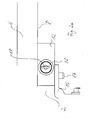
- Fig. 1c is a section A, as in Fig. 1b is indicated, reproduced.
- the spacer element 13 is reproduced in an enlarged view as well as the cooperating parts.
- the spacer element 13 has a lock 16 and is arranged between the lower-side holding element 14, which is fastened to the right strut 3, and the underside 8 of the fence grid frame 6.
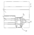
- Fig. 2a is reproduced in a sectional view of the way to the left strut 2 distance element 12.
- This illustration clearly shows that the spacing element 12 is arranged between an angle-shaped holding element 15, which is fastened to the strut 2 by means of a screw, and the underside 8 of the fence-grid frame 6 in its corner area.
- a key 18 is arranged, which is in a vertical position. This key can preferably be rotated 90 ° to open a locking mechanism.
- a bolt 17 engages starting from the corner region of the underside 8 of the fence grid frame 6 through the spacer element 12 into the holding element 15 by means of through holes.
- the spacer 12 consists of a base body 19, which is formed substantially rectangular.
- the main body 19 has a passage opening 22 in which the bolt 7 can be arranged.
- the passage opening 22 is connected along its longitudinal side to a Zuglass barngangsö réelle 23, which is intended for receiving the bolt.
- a wedge-shaped member 22 are moved to the right and then automatically moved by means of a spring, not shown here again to the left, as indicated by the double arrow 21.
- Fig. 2b reproduced representation is clear that it is the struts 2, 3 to profile strips with groove-shaped recesses, which allows a displacement of the holding elements 15 along the grooves to adapt an existing protective fence device on the object of the invention, ie a subsequent Insertion of the spacer elements 12, 13 between the bottom of Zaungitterrahmens 6 and to be moved retaining elements 14, 15 to allow.
- Fig. 2c is the cutout along the section H -.-.- H, as in Fig. 2a is reproduced.
- This illustration shows that the wedge-shaped component 20 can change its position as a function of the rotational position of the cylindrical lock 16 and thereby releases the bolt 17.
- Fig. 3a is shown in a schematic representation in front view of a protective fence device according to a second embodiment of the invention.
- the same and equally important parts are provided with the same reference numerals.
- the safety fence device 1 in turn has the struts 2 and 3 with foot-side fastening elements 4, 5.
- the Zaungitterrahmen 6 is in turn provided between the lower side holding elements 14, 15 and its underside 8 with spacers 12, 13, which allow a closing of the fence grid frame.
- Fig. 3a and 3b reproduced safety fence device according to the second embodiment is different from that in Fig. 1a and 1b reproduced safety fence device according to the first embodiment of the invention in that the two spacer elements 12, 13 by means of a rod member 25, which may be formed square-shaped, for example, also in its cross-section, is connected.
- a rod member 25 which may be formed square-shaped, for example, also in its cross-section.
- the rod member may be extensibly oriented such that it has different lengths between the struts 2, 3.
- Fig. 3c is again shown in an enlarged view clearly represented as a connecting element rod member 25.
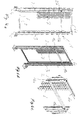
- Fig. 4a and 4b are shown in front and perspective view of a protective fence device according to a third embodiment of the invention.
- the same and equally important parts are provided with the same reference numerals.
- Fig. 4a, 4b, 4c reproduced safety fence device differs from the in Fig. 1a, 1b and 1c such as 3a, 3b and 3c represented safety fence devices in that spacer elements 12a and 13a are arranged between two Zaungitterierin 6, 6a, which may be designed so that either the lower Zaungitterrahmen 6 or the upper Zaungitterrahmen 6a are removable.
- spacer elements 12a and 13a are arranged between two Zaungitterettin 6, 6a, which may be designed so that either the lower Zaungitterrahmen 6 or the upper Zaungitterrahmen 6a are removable.
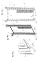
- Fig. 5a a safety fence device according to a fourth embodiment of the invention is shown.
- the same and equally important parts are provided with the same reference numerals.
- FIG. 5a, 5b and 5c reproduced safety fence device shows spacer elements 12b and 13b, which are arranged on the upper side, ie on an upper side 9 of the fence grid frame 6. Again, these spacers are as in Fig. 5c and 6c shown in more detail, disposed between angularly shaped retaining elements 14a and 15a and have a lock 16 for closing the spacer elements.
- Fig. 6c and 6b which is a cross-sectional view along the section D -.-.- D according to FIG Fig. 6a reproduce
- Fig. 6a in a front view reproduced detail clearly show that the basic function of the spacer in interaction with the other components is substantially the same, as already in connection with the FIGS. 2a . 2 B and 2c described.
- a bolt 17a which engages in a passage opening 22 of the base body 19, is arranged.
- a supply passage 23 is formed.
- a locking element which is designed as a wedge-shaped member 20 can be moved along the arrow 21 by spring action to the left and right.
- a safety fence device according to a fifth embodiment of the invention is shown.
- the same and equally important parts are provided with the same reference numerals.
- Fig. 7a, 7b, 7c reproduced safety fence device differs from the in Fig. 5a, 5b and 5c reproduced embodiment of the safety fence device in that the upper side arranged spacer elements 12b and 13b by means of a rod member 25a, which may be formed square in its cross section, are connected. Again, this allows the two spacer elements 12b and 13b are held together when they have been taken out of the intermediate areas between the support members 15a and the top 9 of the fence grid frame 6.
Landscapes
- Engineering & Computer Science (AREA)
- Architecture (AREA)
- Civil Engineering (AREA)
- Structural Engineering (AREA)
- Fencing (AREA)
- Refuge Islands, Traffic Blockers, Or Guard Fence (AREA)
- Catching Or Destruction (AREA)
- Cleaning Or Clearing Of The Surface Of Open Water (AREA)
Applications Claiming Priority (1)
| Application Number | Priority Date | Filing Date | Title |
|---|---|---|---|
| DE102007019195A DE102007019195B3 (de) | 2007-04-20 | 2007-04-20 | Schutzzaunvorrichtung |
Publications (3)
| Publication Number | Publication Date |
|---|---|
| EP1985780A2 true EP1985780A2 (fr) | 2008-10-29 |
| EP1985780A3 EP1985780A3 (fr) | 2009-01-14 |
| EP1985780B1 EP1985780B1 (fr) | 2010-11-17 |
Family
ID=39666081
Family Applications (1)
| Application Number | Title | Priority Date | Filing Date |
|---|---|---|---|
| EP08154756A Not-in-force EP1985780B1 (fr) | 2007-04-20 | 2008-04-18 | Dispositif d'enceinte de protection |
Country Status (3)
| Country | Link |
|---|---|
| EP (1) | EP1985780B1 (fr) |
| AT (1) | ATE488656T1 (fr) |
| DE (2) | DE102007019195B3 (fr) |
Cited By (4)
| Publication number | Priority date | Publication date | Assignee | Title |
|---|---|---|---|---|
| DE102009045413A1 (de) | 2009-10-07 | 2011-04-14 | Eleggs Gmbh Consulting & Components | Befestigungswinkel sowie einen Befestigungswinkel aufweisende Trenneinrichtung |
| EP2407604A1 (fr) * | 2010-07-13 | 2012-01-18 | RK Rose + Krieger GmbH System- & Lineartechnik | Dispositif de connexion |
| FR2997121A1 (fr) * | 2012-10-24 | 2014-04-25 | Cetal | Dispositif de fixation d'un cadre de cloture, claustra ou similaire a un poteau. |
| CN107152190A (zh) * | 2017-06-21 | 2017-09-12 | 湖北美力防护设施科技有限公司 | 组合防护的方法和装置 |
Citations (5)
| Publication number | Priority date | Publication date | Assignee | Title |
|---|---|---|---|---|
| US4355829A (en) | 1980-12-29 | 1982-10-26 | Gregory James E | Gate latch |
| US4465262A (en) | 1982-07-14 | 1984-08-14 | Gary Itri | Portable expandable barrier |
| US4697443A (en) | 1987-02-03 | 1987-10-06 | Hillin Wilbert L | Multi-lock security device |
| EP0835974A1 (fr) | 1996-10-11 | 1998-04-15 | Troax S.A. | Dispositif d'assemblage |
| WO2003016788A1 (fr) | 2001-08-09 | 2003-02-27 | Toshiba Carrier Corporation | Unite exterieure de climatiseur |
Family Cites Families (2)
| Publication number | Priority date | Publication date | Assignee | Title |
|---|---|---|---|---|
| DE4210998A1 (de) * | 1991-04-03 | 1992-10-22 | Papst Hans Dieter | Schutzgitter mit festen rahmenteilen und halteelement hierfuer |
| SE524266C2 (sv) * | 2002-06-12 | 2004-07-20 | Gunnebo Troax Ab | System för avskärmning samt förfarande för montering därav |
-
2007
- 2007-04-20 DE DE102007019195A patent/DE102007019195B3/de not_active Expired - Fee Related
-
2008
- 2008-04-18 EP EP08154756A patent/EP1985780B1/fr not_active Not-in-force
- 2008-04-18 DE DE502008001797T patent/DE502008001797D1/de active Active
- 2008-04-18 AT AT08154756T patent/ATE488656T1/de active
Patent Citations (5)
| Publication number | Priority date | Publication date | Assignee | Title |
|---|---|---|---|---|
| US4355829A (en) | 1980-12-29 | 1982-10-26 | Gregory James E | Gate latch |
| US4465262A (en) | 1982-07-14 | 1984-08-14 | Gary Itri | Portable expandable barrier |
| US4697443A (en) | 1987-02-03 | 1987-10-06 | Hillin Wilbert L | Multi-lock security device |
| EP0835974A1 (fr) | 1996-10-11 | 1998-04-15 | Troax S.A. | Dispositif d'assemblage |
| WO2003016788A1 (fr) | 2001-08-09 | 2003-02-27 | Toshiba Carrier Corporation | Unite exterieure de climatiseur |
Cited By (4)
| Publication number | Priority date | Publication date | Assignee | Title |
|---|---|---|---|---|
| DE102009045413A1 (de) | 2009-10-07 | 2011-04-14 | Eleggs Gmbh Consulting & Components | Befestigungswinkel sowie einen Befestigungswinkel aufweisende Trenneinrichtung |
| EP2407604A1 (fr) * | 2010-07-13 | 2012-01-18 | RK Rose + Krieger GmbH System- & Lineartechnik | Dispositif de connexion |
| FR2997121A1 (fr) * | 2012-10-24 | 2014-04-25 | Cetal | Dispositif de fixation d'un cadre de cloture, claustra ou similaire a un poteau. |
| CN107152190A (zh) * | 2017-06-21 | 2017-09-12 | 湖北美力防护设施科技有限公司 | 组合防护的方法和装置 |
Also Published As
| Publication number | Publication date |
|---|---|
| ATE488656T1 (de) | 2010-12-15 |
| DE502008001797D1 (de) | 2010-12-30 |
| EP1985780B1 (fr) | 2010-11-17 |
| DE102007019195B3 (de) | 2008-10-16 |
| EP1985780A3 (fr) | 2009-01-14 |
Similar Documents
| Publication | Publication Date | Title |
|---|---|---|
| EP2616621B1 (fr) | Grille de protection | |
| EP0526522B1 (fr) | Fermeture a levier pivotant verrouillee par une serrure a pompe | |
| DE69507825T2 (de) | Verbesserungen an sicherheitsgittern | |
| DE2412114A1 (de) | Vorrichtung zum verriegeln bestimmter von mehreren herausziehbaren aufbewahrungseinheiten bei einer aufbewahrungseinrichtung, z.b. einem schrank | |
| EP1985780B1 (fr) | Dispositif d'enceinte de protection | |
| DE102009037977A1 (de) | Absperrelement, insbesondere ein Bauzaun, eine Absperrschranke oder dgl., Vorrichtung zur Verkettung von Absperrelementen und Schwenkvorrichtung zwischen zwei Absperrelementen | |
| DE2706302C3 (de) | Einsteckbügel mit zugehöriger Einsteckkanalausbildung in einem Schloßgehäuse eines Vorhängeschlosses | |
| DE102015114596B4 (de) | Werkzeugschrank | |
| DE102011053263A1 (de) | Leitschwellenschranke sowie Fahrzeugrückhaltesystem mit einer Leitschwellenschranke | |
| DE102014004160B3 (de) | Einrichtung zum Spannen von Strangelementen | |
| WO1991017333A1 (fr) | Fermeture a levier pivotant escamotable munie d'un dispositif a serrure | |
| DE10037186C1 (de) | Schutzgeländer für Tiertransporter | |
| DE102006029822B4 (de) | Vorrichtung zum Sichern von Baustellentüren gegen unrechtmäßiges Eindringen in Gebäude | |
| EP0422254B1 (fr) | Plafond filtrant spécialement pour chambres de pulvérisation | |
| DE4013408A1 (de) | Sicherheitsgitter fuer gebaeudeoeffnungen | |
| DE202022103377U1 (de) | Vorrichtung zur Einbruchsicherung von Fenstern und Türen | |
| DE202016100430U1 (de) | Mobiler Zaun | |
| DE19603417C1 (de) | Vorrichtung zur Sicherung eines zwischen zwei Endstellungen bewegbaren Bauteils zum Verschließen einer Wandöffnung eines Gebäudes | |
| DE9300647U1 (de) | Sicherheitsvorrichtung einer Bautür | |
| DE29903244U1 (de) | Verteilergestell | |
| DE202006018739U1 (de) | Treibstangengetriebe | |
| DE29817064U1 (de) | Ortsveränderliche Tür | |
| EP2534323A2 (fr) | Ensemble de sécurité pour portes coulissantes | |
| DE202013001051U1 (de) | Gegenkasten | |
| DE29802058U1 (de) | Sicherung für aus Stäben zusammengesetzten Rolladen |
Legal Events
| Date | Code | Title | Description |
|---|---|---|---|
| PUAI | Public reference made under article 153(3) epc to a published international application that has entered the european phase |
Free format text: ORIGINAL CODE: 0009012 |
|
| AK | Designated contracting states |
Kind code of ref document: A2 Designated state(s): AT BE BG CH CY CZ DE DK EE ES FI FR GB GR HR HU IE IS IT LI LT LU LV MC MT NL NO PL PT RO SE SI SK TR |
|
| AX | Request for extension of the european patent |
Extension state: AL BA MK RS |
|
| PUAL | Search report despatched |
Free format text: ORIGINAL CODE: 0009013 |
|
| AK | Designated contracting states |
Kind code of ref document: A3 Designated state(s): AT BE BG CH CY CZ DE DK EE ES FI FR GB GR HR HU IE IS IT LI LT LU LV MC MT NL NO PL PT RO SE SI SK TR |
|
| AX | Request for extension of the european patent |
Extension state: AL BA MK RS |
|
| 17P | Request for examination filed |
Effective date: 20090714 |
|
| 17Q | First examination report despatched |
Effective date: 20090812 |
|
| AKX | Designation fees paid |
Designated state(s): AT BE BG CH CY CZ DE DK EE ES FI FR GB GR HR HU IE IS IT LI LT LU LV MC MT NL NO PL PT RO SE SI SK TR |
|
| GRAP | Despatch of communication of intention to grant a patent |
Free format text: ORIGINAL CODE: EPIDOSNIGR1 |
|
| GRAS | Grant fee paid |
Free format text: ORIGINAL CODE: EPIDOSNIGR3 |
|
| GRAA | (expected) grant |
Free format text: ORIGINAL CODE: 0009210 |
|
| AK | Designated contracting states |
Kind code of ref document: B1 Designated state(s): AT BE BG CH CY CZ DE DK EE ES FI FR GB GR HR HU IE IS IT LI LT LU LV MC MT NL NO PL PT RO SE SI SK TR |
|
| REG | Reference to a national code |
Ref country code: GB Ref legal event code: FG4D Free format text: NOT ENGLISH |
|
| REG | Reference to a national code |
Ref country code: CH Ref legal event code: EP |
|
| REG | Reference to a national code |
Ref country code: IE Ref legal event code: FG4D |
|
| REF | Corresponds to: |
Ref document number: 502008001797 Country of ref document: DE Date of ref document: 20101230 Kind code of ref document: P |
|
| REG | Reference to a national code |
Ref country code: NL Ref legal event code: VDEP Effective date: 20101117 |
|
| LTIE | Lt: invalidation of european patent or patent extension |
Effective date: 20101117 |
|
| PG25 | Lapsed in a contracting state [announced via postgrant information from national office to epo] |
Ref country code: LT Free format text: LAPSE BECAUSE OF FAILURE TO SUBMIT A TRANSLATION OF THE DESCRIPTION OR TO PAY THE FEE WITHIN THE PRESCRIBED TIME-LIMIT Effective date: 20101117 Ref country code: NO Free format text: LAPSE BECAUSE OF FAILURE TO SUBMIT A TRANSLATION OF THE DESCRIPTION OR TO PAY THE FEE WITHIN THE PRESCRIBED TIME-LIMIT Effective date: 20110217 |
|
| PG25 | Lapsed in a contracting state [announced via postgrant information from national office to epo] |
Ref country code: LV Free format text: LAPSE BECAUSE OF FAILURE TO SUBMIT A TRANSLATION OF THE DESCRIPTION OR TO PAY THE FEE WITHIN THE PRESCRIBED TIME-LIMIT Effective date: 20101117 Ref country code: SI Free format text: LAPSE BECAUSE OF FAILURE TO SUBMIT A TRANSLATION OF THE DESCRIPTION OR TO PAY THE FEE WITHIN THE PRESCRIBED TIME-LIMIT Effective date: 20101117 Ref country code: PT Free format text: LAPSE BECAUSE OF FAILURE TO SUBMIT A TRANSLATION OF THE DESCRIPTION OR TO PAY THE FEE WITHIN THE PRESCRIBED TIME-LIMIT Effective date: 20110317 Ref country code: SE Free format text: LAPSE BECAUSE OF FAILURE TO SUBMIT A TRANSLATION OF THE DESCRIPTION OR TO PAY THE FEE WITHIN THE PRESCRIBED TIME-LIMIT Effective date: 20101117 Ref country code: BG Free format text: LAPSE BECAUSE OF FAILURE TO SUBMIT A TRANSLATION OF THE DESCRIPTION OR TO PAY THE FEE WITHIN THE PRESCRIBED TIME-LIMIT Effective date: 20110217 Ref country code: NL Free format text: LAPSE BECAUSE OF FAILURE TO SUBMIT A TRANSLATION OF THE DESCRIPTION OR TO PAY THE FEE WITHIN THE PRESCRIBED TIME-LIMIT Effective date: 20101117 Ref country code: CY Free format text: LAPSE BECAUSE OF FAILURE TO SUBMIT A TRANSLATION OF THE DESCRIPTION OR TO PAY THE FEE WITHIN THE PRESCRIBED TIME-LIMIT Effective date: 20101117 Ref country code: FI Free format text: LAPSE BECAUSE OF FAILURE TO SUBMIT A TRANSLATION OF THE DESCRIPTION OR TO PAY THE FEE WITHIN THE PRESCRIBED TIME-LIMIT Effective date: 20101117 Ref country code: IS Free format text: LAPSE BECAUSE OF FAILURE TO SUBMIT A TRANSLATION OF THE DESCRIPTION OR TO PAY THE FEE WITHIN THE PRESCRIBED TIME-LIMIT Effective date: 20110317 Ref country code: HR Free format text: LAPSE BECAUSE OF FAILURE TO SUBMIT A TRANSLATION OF THE DESCRIPTION OR TO PAY THE FEE WITHIN THE PRESCRIBED TIME-LIMIT Effective date: 20101117 |
|
| REG | Reference to a national code |
Ref country code: IE Ref legal event code: FD4D |
|
| PG25 | Lapsed in a contracting state [announced via postgrant information from national office to epo] |
Ref country code: GR Free format text: LAPSE BECAUSE OF FAILURE TO SUBMIT A TRANSLATION OF THE DESCRIPTION OR TO PAY THE FEE WITHIN THE PRESCRIBED TIME-LIMIT Effective date: 20110218 |
|
| PG25 | Lapsed in a contracting state [announced via postgrant information from national office to epo] |
Ref country code: CZ Free format text: LAPSE BECAUSE OF FAILURE TO SUBMIT A TRANSLATION OF THE DESCRIPTION OR TO PAY THE FEE WITHIN THE PRESCRIBED TIME-LIMIT Effective date: 20101117 Ref country code: IE Free format text: LAPSE BECAUSE OF FAILURE TO SUBMIT A TRANSLATION OF THE DESCRIPTION OR TO PAY THE FEE WITHIN THE PRESCRIBED TIME-LIMIT Effective date: 20101117 Ref country code: ES Free format text: LAPSE BECAUSE OF FAILURE TO SUBMIT A TRANSLATION OF THE DESCRIPTION OR TO PAY THE FEE WITHIN THE PRESCRIBED TIME-LIMIT Effective date: 20110228 Ref country code: EE Free format text: LAPSE BECAUSE OF FAILURE TO SUBMIT A TRANSLATION OF THE DESCRIPTION OR TO PAY THE FEE WITHIN THE PRESCRIBED TIME-LIMIT Effective date: 20101117 |
|
| PGFP | Annual fee paid to national office [announced via postgrant information from national office to epo] |
Ref country code: FR Payment date: 20110630 Year of fee payment: 4 |
|
| PG25 | Lapsed in a contracting state [announced via postgrant information from national office to epo] |
Ref country code: RO Free format text: LAPSE BECAUSE OF FAILURE TO SUBMIT A TRANSLATION OF THE DESCRIPTION OR TO PAY THE FEE WITHIN THE PRESCRIBED TIME-LIMIT Effective date: 20101117 Ref country code: DK Free format text: LAPSE BECAUSE OF FAILURE TO SUBMIT A TRANSLATION OF THE DESCRIPTION OR TO PAY THE FEE WITHIN THE PRESCRIBED TIME-LIMIT Effective date: 20101117 Ref country code: PL Free format text: LAPSE BECAUSE OF FAILURE TO SUBMIT A TRANSLATION OF THE DESCRIPTION OR TO PAY THE FEE WITHIN THE PRESCRIBED TIME-LIMIT Effective date: 20101117 Ref country code: SK Free format text: LAPSE BECAUSE OF FAILURE TO SUBMIT A TRANSLATION OF THE DESCRIPTION OR TO PAY THE FEE WITHIN THE PRESCRIBED TIME-LIMIT Effective date: 20101117 |
|
| PLBE | No opposition filed within time limit |
Free format text: ORIGINAL CODE: 0009261 |
|
| STAA | Information on the status of an ep patent application or granted ep patent |
Free format text: STATUS: NO OPPOSITION FILED WITHIN TIME LIMIT |
|
| PGFP | Annual fee paid to national office [announced via postgrant information from national office to epo] |
Ref country code: BE Payment date: 20110621 Year of fee payment: 4 |
|
| 26N | No opposition filed |
Effective date: 20110818 |
|
| PG25 | Lapsed in a contracting state [announced via postgrant information from national office to epo] |
Ref country code: MC Free format text: LAPSE BECAUSE OF NON-PAYMENT OF DUE FEES Effective date: 20110430 |
|
| PGFP | Annual fee paid to national office [announced via postgrant information from national office to epo] |
Ref country code: DE Payment date: 20110630 Year of fee payment: 4 |
|
| REG | Reference to a national code |
Ref country code: DE Ref legal event code: R097 Ref document number: 502008001797 Country of ref document: DE Effective date: 20110818 |
|
| PG25 | Lapsed in a contracting state [announced via postgrant information from national office to epo] |
Ref country code: IT Free format text: LAPSE BECAUSE OF FAILURE TO SUBMIT A TRANSLATION OF THE DESCRIPTION OR TO PAY THE FEE WITHIN THE PRESCRIBED TIME-LIMIT Effective date: 20101117 Ref country code: MT Free format text: LAPSE BECAUSE OF FAILURE TO SUBMIT A TRANSLATION OF THE DESCRIPTION OR TO PAY THE FEE WITHIN THE PRESCRIBED TIME-LIMIT Effective date: 20101117 |
|
| BERE | Be: lapsed |
Owner name: GEHMEYR, MANFRED Effective date: 20120430 Owner name: HELD, HEINZ Effective date: 20120430 |
|
| REG | Reference to a national code |
Ref country code: CH Ref legal event code: PL |
|
| GBPC | Gb: european patent ceased through non-payment of renewal fee |
Effective date: 20120418 |
|
| REG | Reference to a national code |
Ref country code: FR Ref legal event code: ST Effective date: 20121228 |
|
| PG25 | Lapsed in a contracting state [announced via postgrant information from national office to epo] |
Ref country code: CH Free format text: LAPSE BECAUSE OF NON-PAYMENT OF DUE FEES Effective date: 20120430 Ref country code: LI Free format text: LAPSE BECAUSE OF NON-PAYMENT OF DUE FEES Effective date: 20120430 Ref country code: BE Free format text: LAPSE BECAUSE OF NON-PAYMENT OF DUE FEES Effective date: 20120430 Ref country code: GB Free format text: LAPSE BECAUSE OF NON-PAYMENT OF DUE FEES Effective date: 20120418 |
|
| REG | Reference to a national code |
Ref country code: DE Ref legal event code: R119 Ref document number: 502008001797 Country of ref document: DE Effective date: 20121101 |
|
| PG25 | Lapsed in a contracting state [announced via postgrant information from national office to epo] |
Ref country code: FR Free format text: LAPSE BECAUSE OF NON-PAYMENT OF DUE FEES Effective date: 20120430 |
|
| PG25 | Lapsed in a contracting state [announced via postgrant information from national office to epo] |
Ref country code: LU Free format text: LAPSE BECAUSE OF NON-PAYMENT OF DUE FEES Effective date: 20110418 |
|
| PG25 | Lapsed in a contracting state [announced via postgrant information from national office to epo] |
Ref country code: TR Free format text: LAPSE BECAUSE OF FAILURE TO SUBMIT A TRANSLATION OF THE DESCRIPTION OR TO PAY THE FEE WITHIN THE PRESCRIBED TIME-LIMIT Effective date: 20101117 |
|
| PG25 | Lapsed in a contracting state [announced via postgrant information from national office to epo] |
Ref country code: HU Free format text: LAPSE BECAUSE OF FAILURE TO SUBMIT A TRANSLATION OF THE DESCRIPTION OR TO PAY THE FEE WITHIN THE PRESCRIBED TIME-LIMIT Effective date: 20101117 |
|
| REG | Reference to a national code |
Ref country code: AT Ref legal event code: MM01 Ref document number: 488656 Country of ref document: AT Kind code of ref document: T Effective date: 20130418 |
|
| PG25 | Lapsed in a contracting state [announced via postgrant information from national office to epo] |
Ref country code: AT Free format text: LAPSE BECAUSE OF NON-PAYMENT OF DUE FEES Effective date: 20130418 |
|
| PG25 | Lapsed in a contracting state [announced via postgrant information from national office to epo] |
Ref country code: DE Free format text: LAPSE BECAUSE OF NON-PAYMENT OF DUE FEES Effective date: 20121101 |