EP1986155A2 - Analyse de spécimen et analyseurs de région aciculaire - Google Patents
Analyse de spécimen et analyseurs de région aciculaire Download PDFInfo
- Publication number
- EP1986155A2 EP1986155A2 EP08250902A EP08250902A EP1986155A2 EP 1986155 A2 EP1986155 A2 EP 1986155A2 EP 08250902 A EP08250902 A EP 08250902A EP 08250902 A EP08250902 A EP 08250902A EP 1986155 A2 EP1986155 A2 EP 1986155A2
- Authority
- EP
- European Patent Office
- Prior art keywords
- image
- acicular
- region
- specimen
- counting
- Prior art date
- Legal status (The legal status is an assumption and is not a legal conclusion. Google has not performed a legal analysis and makes no representation as to the accuracy of the status listed.)
- Withdrawn
Links
Images


Classifications
-
- G—PHYSICS
- G06—COMPUTING OR CALCULATING; COUNTING
- G06T—IMAGE DATA PROCESSING OR GENERATION, IN GENERAL
- G06T7/00—Image analysis
- G06T7/0002—Inspection of images, e.g. flaw detection
- G06T7/0004—Industrial image inspection
-
- G—PHYSICS
- G01—MEASURING; TESTING
- G01N—INVESTIGATING OR ANALYSING MATERIALS BY DETERMINING THEIR CHEMICAL OR PHYSICAL PROPERTIES
- G01N15/00—Investigating characteristics of particles; Investigating permeability, pore-volume or surface-area of porous materials
- G01N15/10—Investigating individual particles
- G01N15/14—Optical investigation techniques, e.g. flow cytometry
- G01N15/1429—Signal processing
- G01N15/1433—Signal processing using image recognition
-
- G—PHYSICS
- G01—MEASURING; TESTING
- G01N—INVESTIGATING OR ANALYSING MATERIALS BY DETERMINING THEIR CHEMICAL OR PHYSICAL PROPERTIES
- G01N15/00—Investigating characteristics of particles; Investigating permeability, pore-volume or surface-area of porous materials
- G01N2015/0042—Investigating dispersion of solids
- G01N2015/0053—Investigating dispersion of solids in liquids, e.g. trouble
-
- G—PHYSICS
- G01—MEASURING; TESTING
- G01N—INVESTIGATING OR ANALYSING MATERIALS BY DETERMINING THEIR CHEMICAL OR PHYSICAL PROPERTIES
- G01N15/00—Investigating characteristics of particles; Investigating permeability, pore-volume or surface-area of porous materials
- G01N15/10—Investigating individual particles
- G01N15/14—Optical investigation techniques, e.g. flow cytometry
- G01N15/1434—Optical arrangements
- G01N2015/1454—Optical arrangements using phase shift or interference, e.g. for improving contrast
-
- G—PHYSICS
- G01—MEASURING; TESTING
- G01N—INVESTIGATING OR ANALYSING MATERIALS BY DETERMINING THEIR CHEMICAL OR PHYSICAL PROPERTIES
- G01N15/00—Investigating characteristics of particles; Investigating permeability, pore-volume or surface-area of porous materials
- G01N15/10—Investigating individual particles
- G01N15/14—Optical investigation techniques, e.g. flow cytometry
- G01N2015/1486—Counting the particles
-
- G—PHYSICS
- G06—COMPUTING OR CALCULATING; COUNTING
- G06T—IMAGE DATA PROCESSING OR GENERATION, IN GENERAL
- G06T2207/00—Indexing scheme for image analysis or image enhancement
- G06T2207/10—Image acquisition modality
- G06T2207/10141—Special mode during image acquisition
- G06T2207/10152—Varying illumination
Definitions
- the present invention relates to a method for analyzing a specimen included in an image, and an apparatus using the method. More specifically, the present invention relates to a method for counting particle regions and acicular regions using an image processing technique, and an apparatus employing this method.
- Non-Patent Document 1 provides, as qualitative analysis means, two methods: the dispersion staining method using a phase-contrast microscope, and the extinction-angle method using a polarization microscope.
- a preparation prepared by pulverizing a sample extracted from a building material and immersing the pulverized sample in a liquid of known refractive index (hereinafter referred to as "immersion liquid”) is visually observed under a phase-contrast microscope or a polarization microscope to determine whether or not fibers exist based on its colors and shapes.
- Non-Patent Document 1 the dispersion staining method may be used in practice as a quantitative analysis method (see, for example, "Notice Regarding Methods for Analyzing the Content of Asbestos in Building Materials", Bureau Chief's Notice No. 0821002, Chief of Labor Standards Bureau, Ministry of Health, Labor and Welfare, Japanese Government (Non-Patent Document 2)). Also, a phase-contrast microscope for performing such dispersion staining method with high accuracy is disclosed in JP 2005-338567 A (Patent Document 1) .
- the observer When determining whether or not asbestos exists by means of the dispersion staining method according to the description in Non-Patent Document 1 (hereinafter, referred to as the "Official Protocol"), the observer first prepares a specimen (such as a pulverized building material) from a sample (such as a building material) by means of a predetermined method. Then, the observer loads the specimen on the stage of the phase-contrast microscope. Next, the observer sets a dispersion staining objective lens with a magnification of 10x and checks whether there is a fiber that exhibits a dispersion color according to a kind of asbestos (chrysotile, amosite and crocidolite).
- a specimen such as a pulverized building material
- a sample such as a building material
- the observer sets a dispersion staining objective lens with a magnification of 40x, and further, counts all the particles, including fibrous particles, existing within an eyepiece graticule circle with a diameter of 100 ⁇ m seen in the eyepiece lens (10x) of the phase-contrast microscope, and continues the counting while shifting his/her point of view until the total number of particles reaches 1000.
- the observer then records the kind and particle count of the asbestos exhibiting the dispersion color.
- the Official Protocol since it provides that three specimens are to be prepared for a single sample undergoing the analysis and also since it requires respective immersion liquid for a kind of asbestos, the abovementioned observation and counting are performed for nine specimens in total for a single sample.
- Non-Patent Document 2 Building materials are regulated according to a prescribed regulation value as to whether or not they include fibrous particles that are determined to be asbestos in the total number of particles based on a result of the aforementioned observation. This regulation value was lowered to 0.1% in 2006 from the conventional value of 1%, whereby the regulation has been substantially strengthened (Non-Patent Document 2).
- JP 2005-233658 A discloses an automatic determination method and judgment apparatus for asbestos.
- the content of asbestos is calculated using an element map image based on a characteristic X-ray together with a shape map image, that is, using element analysis together with image analysis.
- analysis means for performing element analysis is required.
- Patent Document 1 JP 2005-338567 A
- Patent Document 2 JP 2005-233658 A
- Non-Patent Document 1 "Methods for Measuring the Content of Asbestos in Building Materials", Japanese Industrial Standards (JIS) A1481, Established on March 25, 2006
- Non-Patent Document 2 "Notice Regarding Methods for Analyzing the Content of Asbestos in Building Materials", Bureau Chief's Notice No.
- An object of the present invention is to solve at least one of the aforementioned problems by analyzing a specimen using an image processing technique.
- the present invention involves counting acicular regions or particle regions from an image using an image processing technique, in order to, for example, assist an observer with his/her visual observation-based determination of specimens for qualitative analysis in the aforementioned Official Protocol, or provide a substitute method for visual judgment.
- the present invention provides a specimen analysis method for analyzing an acicular crystal in a specimen of an unidentified sample using a captured image of the specimen, the method comprising steps of: capturing a first image of an imaging area in the specimen under a first imaging condition; capturing a second image of the imaging area in the specimen under a second imaging condition, the first imaging condition and the second imaging condition being conditions providing mutually different data on an image of the acicular crystal or an area neighboring the image in their captured images; counting a particle region by setting, as an original image, any of the first image, the second image or a third captured image of the imaging area in the specimen, counting the number of regions that have pixel values different from a pixel value of a background in the original image, and at least storing or outputting the result of the counting; and counting an acicular region by obtaining a differential image based on a difference in data between the first image and the second image, selecting acicular regions based on the differential image, counting the number of the selected acicular regions, and at
- the present invention provides an analysis method in which the unidentified sample is an unidentified sample of a pulverized building material; the specimen is a specimen prepared by immersing the sample of the pulverized building material in an immersion liquid having a known refractive index substantially equal to a refractive index of an asbestos crystal of a kind that may be contained in the sample; the first imaging condition and the second imaging condition are conditions for capturing an image of the specimen using a phase-contrast microscope in which their respective azimuths of a polarizer inserted from the specimen to an optical path are different for each condition; the method further includes steps of:
- the present invention provides an acicular region analysis system.
- a specimen analysis system for analyzing an acicular crystal in a specimen of an unidentified sample using a captured image of the specimen, the system comprising: an image capturing unit adapted to take an image of the specimen of the unidentified sample according to a plurality of imaging conditions to capture image data; a first image recording unit for storing first image data for an imaging area in the specimen, the first image data being captured by the image capturing unit according to a first imaging condition; a second image recording unit for storing second image data for the imaging area in the specimen, the second image data being captured by the image capturing unit according to a second imaging condition, the first imaging condition and the second imaging condition being conditions providing mutually different data on an image of the acicular crystal or an area neighboring the image in their taken images; a particle region counting unit that sets any of the first image, the second image or a third image taken of the imaging area in the specimen, as an original image, and at least counts the number of regions in
- An unidentified sample intended by the present invention is a material that can be a specimen to be used for imaging for analyzing acicular crystals.
- solid materials such as building materials are typical examples of this unidentified sample
- the solid materials may arbitrarily include mixtures and composite materials, etc., and not only solid materials, but also mixtures of solid materials and liquids such as waste solution and sludge, powders such as substances collected by fibrous trapping materials such as a membrane filter that samples suspended particles from a gas may be used.
- the collection target can arbitrarily determined; it may be a natural product, such as soil or minerals, a biological sample from a laboratory animal or a human body, or an artificial product created in what is called nanotechnology field.
- the unidentified sample used in the present invention may be any sample for which existence or non-existence of acicular substances is judged or the acicular substances are counted using an image, for example.
- the specimen is typically a preparation for a microscope, prepared by processing such unidentified sample to be suitable for observation, and the specific structure and size, etc., are not limited.
- the imaging area is an area for which an image that is the object of image processing is captured.
- the imaging area may have a round shape conforming to a graticule, or for preliminary processing before carrying out the Official Protocol, it may have a quadrangular shape with an appropriate aspect ratio to be suited for computer processing.
- the image is typically the whole or a part of an image taken by a microscope using visible light, and may be an arbitrary image with no limitations with regard to the physical means used for imaging and the shape of the image itself, etc.
- the image is captured in the form of data that can be electronically processed.
- regions having pixel values different from that of the background are counted by grayscaling the original image, for example.
- the number of target objects is determined by a counting process.
- the imaging conditions are conditions for capturing an image. At least a part of the imaging conditions includes a condition enabling selection of a plurality of conditions that may change pixel value data for the image of the acicular crystal or the area neighboring the image.
- a condition enabling selection of a plurality of conditions that may change pixel value data for the image of the acicular crystal or the area neighboring the image.
- the imaging conditions in the present invention are not limited to those for capturing an image by the imaging device, and include arbitrary conditions for, for example, changing the conditions for radiation, such as light, used for capturing images and changing the state of the specimen.
- the present invention further provides an apparatus for reviewing a specimen and a computer program.
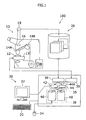
- FIG. 1 is a block diagram illustrating the configuration of an analysis system 100, which is an embodiment of the present invention.
- a phase-contrast microscope 10 includes a stage 13 on which a specimen 12 is mounted, and also includes dispersion staining objective lenses 14A and 14B that can be set in a position facing the specimen 12.
- An image sensor 18 for capturing an image in the form of electric signals is attached to the phase-contrast microscope 10, and an analyzer 16 is disposed at the optical path between the dispersion staining objective lens 14A or 14B and a camera.
- An image captured by the image sensor 18 is stored in an arbitrary computer apparatus (not shown), or arbitrary storage means 20, such as image database, that can store images, in such a manner that the stored image can be identified.
- the analysis system 100 further includes a computer 30.
- the computer 30 includes input/output devices such as a display 32, a keyboard 33, a mouse 34, and also includes computing means 35 and storage means 36.
- the analysis system 100 includes an input/output interface unit 38 for capturing image data and a control board 39 for controlling external devices.
- This input/output interface may be a general-purpose interface such as IEEE1394 or USB, for example.
- the control board for controlling external devices may be a device control interface such as GP-IB, for example.
- a particle counting unit 42 and an acicular region counting unit 44 are provided by means of the computing means 35, and the particle count recording unit 46 and an acicular region count recording unit 48 are also provided by means of the storage means 36.
- the acicular region counting unit 44 includes an acicular region selecting unit 44A.
- the computer 30 can read data from, for example, an image file or an image record in the storage means 20 that stores images.
- the present embodiment can be provided by means of the aforementioned device configuration. Hereinafter, specific processing according to the present embodiment will be described with reference to the drawings.
- FIG. 2 is a flowchart illustrating the overview of processing according to the embodiment of the present invention.
- an image is captured using the analysis system 100 shown in FIG. 1 (S12), and particle counting processing S20 and acicular region counting processing S30 are performed using the captured image, and specimen analysis processing S14 using these data is performed.
- FIG. 3 is a flowchart illustrating the image capture processing S12.
- a clean preparation slide with no sample contained is provided to take an image of it (S122).
- S122 image of it
- the background image is stored in proper storage means (for example, storage means 20).
- the specimen is provided (S124).
- the specimen is prepared in advance from a sample, such as a building material, that is the target of the analysis.
- the processing at this stage is performed according to, for example, the procedure set forth in the Official Protocol.
- the thus-provided specimen is loaded on the stage 13 in the form of a preparation.
- the specimen can be loaded on a stage, etc., that can perform preset operations, by means of a proper loader (not shown), etc.
- the thus-provided specimen then proceeds to image capturing.
- the stage 13 includes coordinate detection means (not shown) such as a rotary encoder, and such record may be stored in relation to image data. In that case, information indicating the relationship with the image data can be stored in the storage means 36 shown in FIG. 1 .
- Image capturing starts from a step where the stage 13 is moved to the imaging area (S126) so that the imaging area such as the particular position of the preparation, for example, is included in the field of view of the microscope.
- a first imaging condition is set (S128), and then a first image is taken according to the first imaging condition (S128A).
- Imaging condition setting and image capturing according to that condition are repeated at least twice, including this processing for the first image; thus, second imaging condition setting (S130) and second image-taking are also performed (S130A).
- the first imaging condition and the second imaging condition are conditions that provide mutually different data on the image of an acicular crystal and an area neighboring the image in their captured images.
- This third imaging condition can be set as an imaging condition that, when it is necessary to count the number of particles imaged in the Official Protocol, for example, is useful for the particle counting.
- This third imaging condition can be set as an imaging condition that, when it is necessary to count the number of particles imaged in the Official Protocol, for example, is useful for the particle counting.
- the insertion and removal of the analyzer into and from the optical path, and the azimuth of the analyzer can be provided by drive means as necessary, and controlled by a computer. When capturing images of one imaging area has been completed as described above, the imaging area is shifted to another imaging area as necessary.
- the processing for identifying a particle candidate region (S22) is performed.
- the present embodiment is described so that the acicular region counting processing (S30) is executed after the particle counting processing (S20) is performed, this order of processing can be reversed, or these processing can also be performed simultaneously using separate processors.
- any of the first to third images captured as a result of the processing shown in FIG. 3 can be used.
- the background image is used.
- a particle candidate region in the present embodiment is a region that the image processing may determine to have a high possibility of containing a particle in the image.
- the processing for grayscaling the captured original image is performed (S222). This grayscaling makes it possible to, for example, use data for only a particular original color from among image data captured in the three original color (RGB) format and discard the other data, or use processing such as making the data be luminance data by means of proper matrix computation.
- RGB original color
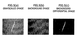
- FIG. 5(A) An example of a specimen image and a grayscaled image used in this processing are shown in FIG. 5(A) .
- differential processing is processing for subtracting data for the pixels of the grayscaled background image from data for the pixels of the grayscaled original image.
- differential processing sparse noise components contained in the image remain in a nonzero value, and they may become indistinguishable from the particles in the subsequent processing, and accordingly, the processing for removing such noise components is performed (S226).
- This noise removal processing is processing for making data for a pixel whose differential-image pixel value is equal to or lower than a certain value be 0.
- a background differential image is obtained by reducing the background components and removing the noise components.
- FIG. 5 shows an image in which an image taken of a specimen has been grayscaled ( FIG. 5(A) ); an image in which an image taken of a background has been grayscaled ( FIG. 5(B) ); and a background differential image created from these images ( FIG. 5(C) ).
- the background differential image an image in which image irregularities and noises have been removed can be obtained.
- FIGS. 6 and 7 show the processing flow of this particle detection processing.
- particles are detected by setting different threshold values for the respective candidate regions using the discriminant analysis method (S240).
- a candidate region refers to a region surrounded by pixels having a pixel value equal to or close to 0 in a background differential image.
- a background differential image as described above, is one obtained by subtracting a background image from an original image after grayscaling, and an image having a pixel value equal to or close to 0 at that time corresponds to an image having a pixel value obtained by subtracting the pixel value of the grayscaled background level from the grayscaled original image. Since noise removal processing has been performed previously, there may also be a minor difference when the pixel value is a small but nonzero value; however, such difference is not essential.
- the candidate regions are associated with different thresholds values.
- One of the methods for determining these threshold values based only on the statistical nature of data for the respective candidate regions is the discriminant analysis method.
- Other than the discriminant analysis method methods such as the p-tile method and the mode method can be used.
- a histogram is classified by a certain threshold value into two classes; a threshold value at which the ratio between the interclass dispersion and the intra-class dispersion becomes a maximum (local maximum) is calculated, and that threshold value is used as the threshold value for classification.
- a threshold value is set for a candidate region by means of a grayscaled image expressed by 256-shade pixel values, for example, using a threshold value t
- n k is the number of pixels having a pixel value of k.
- FIG. 7 shows the flow of the processing for setting a threshold value using this discriminant analysis method.
- the threshold value t is set to be an appropriate value (S242)
- the interclass dispersion is calculated according to Formula 4 (S244A)
- the intra-class dispersion is calculated according to Formula 5 (S244B).
- This order of processing may be reversed.
- the dispersion ratio is calculated from the interclass dispersion and the intra-class dispersion according to Formula 6 (S244C).
- S246 whether or not there is any remaining threshold value to be used
- the threshold value is set to a new value and the calculation is repeated.
- the threshold value that provides the maximum dispersion ratio is extracted (S248).
- the initial value of the threshold value for the loop calculation shown in FIG. 7 is set to 0, for example, and in the threshold value setting S242, the threshold value is incremented.
- a device for further enhancing the accuracy is made. Even though the aforementioned noise removal is performed, noise may still remain in the background differential image. At that time, since the images of the particles including ones in the form of acicular crystals are accompanied by the reflection (or halo) of the phase-contrast microscope 10, positional changes can be seen in the pixel values in the candidate region, while such change cannot be seen in noise. Accordingly, in the image data for such images, the pixel values of the regions with changes or variations smaller than a certain value are set to 0. This processing is referred to as "non-variation noise removal" in the present invention.
- this certain value may greatly vary depending on the imaging conditions of the image, etc., it may be determined empirically.
- FIG. 6 also shows the processing after the processing for determining the threshold values for the candidate regions (S240) .
- each candidate region is binarized by the threshold value related to the candidate region, and this is repeated with regard to all the candidate regions (S256).
- all the candidate regions within the background differential image are binarized.
- the variation of each candidate region is compared with a variation threshold value (S250), all the pixel values in the candidate region that exhibit only a variation smaller than the variation threshold value are made to 0 (S252).
- S254 an image (binary image) in which only the pixels are observed as particles in the phase-contrast microscope have values that are not 0 can be obtained.
- the thus-obtained binary image correctly reflects the positions of particles as image data.
- the number of particles in this binary image is totaled ( FIG. 2 , S26) .
- labeling processing is employed for this processing.
- FIG. 8 shows the processing for counting the number of particles including labeling processing.
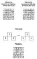
- FIG. 9 shows explanatory diagrams illustrating the relationship between a pixel of interest and its neighboring pixels
- FIG. 10 is an explanatory diagram for describing the conditions used in labeling processing.
- the processing is performed by detecting four neighboring connection components ( FIG. 9(A) ) and eight neighboring connection components ( FIG. 9(B) ) in neighboring pixels of a pixel of interest. More specifically, a raster scan is performed twice on the image to search for four neighboring connection components ( FIG. 8 , S262 and S264), and one more raster scan is performed to search for eight neighboring connection components (S266).
- the four neighboring connection components can be obtained by performing the raster scan while performing the processing according to the following four conditions on the pixel of interest, and performing the processing twice:
- FIG. 11 shows an example of labeling after the first scan, and an example of labeling after the second scan.
- the main scan is performed rightward from the upper left side, and the vertical scan is performed downward from the upper side, thereby shifting the pixel of interest.
- FIG. 11 shows the result of the processing according to the aforementioned four conditions being applied to the pixels once ( FIG. 11(A) ) and the result of the processing being applied once more (( FIG. 11(A) ) in these scans.
- FIG. 12 shows the state of this processing.
- the label of the pixel of interest is compared with the label of the lower left pixel, and also, the label of the pixel of interest is compared with the label of the lower right pixel, and sequentially making the labels be the same so that the label of the pixel of interest is the same as those of the lower left and lower right pixels.
- FIG. 12(A) shows the state in which the labels are made to be the same at this stage.
- labeling processing providing eight connected neighboring pixels is performed.
- the number of labeled regions is counted after such labeling processing, and such number is determined to be the number of particles contained in the binary image.
- the particles in the image are counted irrespective of their shapes. Accordingly, they are counted irrespective of whether or not the particles seen in the processing target image (any of the first to third images) are acicular crystals.
- the acicular region counting processing consists of the processing for identifying an asbestos crystal candidate (S32), and the processing for detecting an asbestos crystal (S34), and the processing for counting the number of asbestos crystals and identifying the crystals (S36).
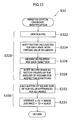
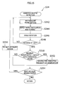
- the processing for identifying an asbestos crystal candidate will be described with reference to FIG. 13 .
- the asbestos crystals are measured using the first image taken according to the first imaging condition, and the second image taken according to the second imaging condition.
- these images are a pair of images taken by changing the azimuths of the analyzer, for example.
- the images of the imaging area that are completely the same can be obtained in principle, but in actual use where measurement is performed using a microscope, the position where the image is captured may be shifted when observed minutely, due to the effect of machinery vibration or the rotational components such as the analyzer. In many cases, such shifting occurs in a parallel direction, but even such minute shifting of the imaging area may cause an impact on the processing for counting acicular regions.
- position correction processing (or aligning processing) S320 is performed for such unintended shifting, and then, the processing for the two images is performed (S330).
- the position correction processing S320 is started by grayscaling the first image and the second image. Grayscaling is executed to exclude irregularities in data with poor coherency that can often be seen when original three color data (RGB data) is used and accurately calculating a shift vector. Accordingly, it is preferable that one value for each pixel is calculated using RGB data when grayscaling is performed.
- the grayscaling is performed for position correction, but the subsequent processing (S330) is performed on an image that is not grayscaled.
- a shift vector is a vector necessary to superpose the pixels of one image on the pixels of the other image, and it can be calculated for each pixel, depending on where the same pixel value as that of data for a pixel in one grayscaled image appears among corresponding neighboring pixel positions in the other image. More specifically, a pixel having the same pixel value as that of a pixel of interest (x 1i , y 1i ) in one image is searched for from 48 pixels in the other image neighboring the position of the corresponding pixel of interest (x 2i , y 2i ) (the range of 7 by 7 pixels).
- the second image which is not grayscaled, is shifted by the shift vector created by the thus-obtained medians (S328) to make it to a new second image.
- this new second image is simply referred to the second image.
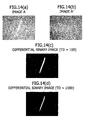
- FIG. 14 An example of an image at each stage of obtaining a binary image in such a manner described above is shown in FIG. 14.
- FIGS. 14(A) and 14(B) show the first image and the second image used in this processing
- FIGS. 14(C) and 14(D) each show a binary image obtained by the processing S32 for identifying an asbestos crystal candidate from the first image and second image where td is 100 and where td is 1000, respectively.
- td is set to a small value, for example, 100. This is because if td is set to a large value, for example, 1000, the possibility that the regions not selected as acicular regions may include regions that should be judged to be asbestos when counting asbestos, for example, is increased.
- a rectangular region is set in an acicular region in a binary image (S342).
- This rectangular region is a quadrangle that may be a rectangle or a square circumscribing the acicular region. Since the rectangle can turn to any direction, there are numerous setting methods, but here, the direction is determined according to an x-y coordinate that provides the positions of the pixels of image data.
- the range of the x-coordinate included in the acicular region corresponds to the length in the x-direction of the rectangular region, and the range of the y-coordinate corresponds to the length in the y-direction.
- the aspect ratio can be calculated (5344) .
- the aspect ratio is stored in a proper storage unit in relation to the acicular region.
- the image is rotated.
- the image is rotated by every 30 degrees.
- the image can easily be rotated by rotational transformation (S346).
- the aspect ratio is measured for each angle, and this processing loop is terminated when the image is rotated by 180 degrees (S348). Then, the maximum value is selected from the stored aspect ratios for the respective rotation angles.
- acicular regions are selected focusing on their shapes. For example, in a qualitative analysis of asbestos employing the present embodiment, whether or not the particle is counted is determined depending on whether its aspect ratio is no less than 3:1 or less than 3:1. Accordingly, in the present embodiment, the reference value for selecting a particle as an acicular region is set to an aspect ratio of a value close to and smaller than 3:1, for example, 2.0:1. Then, the reference value is compared with the maximum value of the aspect ratio (S350), if the maximum value exceeds the reference value, the relevant acicular region is marked (S352). This processing is repeated until no acicular regions appear in the imaging area (S354 and S356).
- Tables 1 to 3 show data indicating the detection failure count and erroneous detection count when the aspect ratio reference value has been changed for chrysotile, amosite and crocidolite, respectively. Although some differences can be seen depending on the kind of asbestos, all of the data shows small values in both the detection failure count and the erroneous detection count at aspect ratio reference values of around 2.0:1, which shows that the analysis method according to the present embodiment can be employed.
- the present invention provides not only an analysis method and an analysis system, but also counting processing for an observer to re-conduct an acicular region judgment based on an image or in particular, specifying the position for acicular region observation, using the method according to the aforementioned embodiment as a screening method before the observer reviews the specimen.
- the proper storage means storing information (image correspondence information) for identifying acicular regions and relating them to the images, as an image relation storing unit
- image correspondence information information for identifying acicular regions and relating them to the images
- an acicular region is specified by, for example, by the receipt of selection of the acicular region from an observer or as a result of the acicular region being selected according to some rule such as sequentially displaying acicular regions having a certain aspect ratio or larger when they are found
- the corresponding image is specified based on the information in the image relation storing unit, and the image is retrieved up afterward to show it on the display.
- the observer can retrieve the image of the judged acicular region, and review the region based on the image.
- information for identifying acicular regions and positional information for specifying the positions of the acicular regions in the specimen are related to each other.
- stage encoder information for identifying acicular regions by means of proper IDs and specifying an imaging area according to those IDs, and coordinate data indicating the positions of acicular regions in the imaging area are held in a coordinate data storing unit.
- the positional information for the selected acicular region is retrieved up from the positional data storing unit. Visual observation is conducted using the same microscope used at the stage of the initial image being taken, or another microscope using a preparation with a device enabling position specification.
- observation is carried out using a microscope having an automatic stage that can be controlled from the device control interface of the computer 30, or the observer can move the stage manually by showing the movement destination coordinate to the observer via the display 32.
- the observer can visually observe an object judged to be an acicular region through the eyepiece lens of a microscope, or through a direct image from the camera 18 shown in FIG. 1 .
- the particle measurement according to the present embodiment provides sufficient accuracy and it is sufficient as processing used for preliminary processing for analysis.
- the embodiment can properly count the number of particles by means of processing using a computer, which is different from a judgment according to the conventional Official Protocol in which thousands of particles are visually observed using a microscope, and it enables an observer to perform an observation focusing on visual judgment of acicular regions, providing a sufficient advantageous effect.
- the acicular region counting processing S30 was performed on the images shown in Table 4.
- Table 6 shows the asbestos counts obtained by actual visual observations and the asbestos counts obtained by the measurement for the respective samples.
- the Table also provides the average detection failure count and the average erroneous detection count per image. As shown in the Table, it was confirmed that the analysis method according to the present embodiment has usefulness that can provide sufficient assistance for an observer's visual observation also in crystal counting.
- any of the aspects of the present invention it is possible to, at least when an observer observes an image to search for, for example, asbestos using, for example, the Official Protocol, count numerous particles in the observation object specimen, and count candidates that may be asbestos from them. Also, it is possible to enhance the accuracy of particle counting, or the accuracy of acicular crystal counting.
- any of the aspects of the present invention it is possible to, when observing, for example, asbestos using, for example, the Official Protocol, assist an observer with the observation, and reduces the burden on the observer. Also, according to the present invention, at least a part of an acicular crystal analysis of, for example, asbestos according to the aforementioned current Official Protocol or the other methods using images can be conducted.
- an observer it is possible for an observer to retrieve an image identified as an acicular region onto a display for review, or to visually review the specimen at the position where the specimen is identified as an acicular region.
- the present invention is not limited to the aforementioned embodiment, various alterations, modifications and combinations are possible based on the technical idea of the present invention.
- the imaging area is shifted immediately after the capture of an image, but it is also possible that each imaging area is shifted after the image capture S12 to the specimen analysis processing S14 are performed for the imaging area.
- phase-contrast microscope Although the description has been made mainly on an embodiment using a phase-contrast microscope, other types of imaging apparatus can also be used. For example, it is possible to, using a polarization microscope instead of a phase-contrast microscope, rotate a polarizer and an analyzer included in the polarization microscope at an angle maintained between them, or analyze a specimen at least using two images obtained by rotating the stage. Also, the scope of the claims in the present application includes the use of any image capture means providing acicular crystal image data or image-neighboring data that may vary depending on the imaging condition, besides the techniques in which images can be captured by an optical microscope.
- these azimuths may be a combination of arbitrary angles perpendicular to each other, and for example, when the tone difference greatly varies depending on the relationship between the direction of the crystal and the azimuth of the analyzer, an image according to another azimuth can be added.
- the imaging conditions that may change acicular crystal image data or image-neighboring data may include, for example, changing the temperature of the specimen to take an image of it using the temperature dependency of the refractive index of an immersion liquid for asbestos detection, and thus, they are not limited to conditions for an apparatus for image-taking, and include arbitrary conditions relating to acicular crystal images.
Landscapes
- Engineering & Computer Science (AREA)
- Physics & Mathematics (AREA)
- General Physics & Mathematics (AREA)
- Chemical & Material Sciences (AREA)
- Quality & Reliability (AREA)
- Computer Vision & Pattern Recognition (AREA)
- Theoretical Computer Science (AREA)
- Dispersion Chemistry (AREA)
- Signal Processing (AREA)
- Health & Medical Sciences (AREA)
- Life Sciences & Earth Sciences (AREA)
- Analytical Chemistry (AREA)
- Biochemistry (AREA)
- General Health & Medical Sciences (AREA)
- Immunology (AREA)
- Pathology (AREA)
- Investigating Or Analysing Materials By Optical Means (AREA)
Applications Claiming Priority (1)
| Application Number | Priority Date | Filing Date | Title |
|---|---|---|---|
| JP2007115157A JP5223069B2 (ja) | 2007-04-25 | 2007-04-25 | 標本の分析方法およびそれを利用した針状領域の分析装置 |
Publications (2)
| Publication Number | Publication Date |
|---|---|
| EP1986155A2 true EP1986155A2 (fr) | 2008-10-29 |
| EP1986155A3 EP1986155A3 (fr) | 2009-09-16 |
Family
ID=39629274
Family Applications (1)
| Application Number | Title | Priority Date | Filing Date |
|---|---|---|---|
| EP08250902A Withdrawn EP1986155A3 (fr) | 2007-04-25 | 2008-03-17 | Analyse de spécimen et analyseurs de région aciculaire |
Country Status (3)
| Country | Link |
|---|---|
| US (1) | US20080267469A1 (fr) |
| EP (1) | EP1986155A3 (fr) |
| JP (1) | JP5223069B2 (fr) |
Cited By (4)
| Publication number | Priority date | Publication date | Assignee | Title |
|---|---|---|---|---|
| WO2018071958A1 (fr) | 2016-10-21 | 2018-04-26 | First Frontier Pty Ltd | Système et procédé d'analyse automatisée d'échantillons d'air |
| AU2018101327B4 (en) * | 2016-10-21 | 2019-04-18 | First Frontier Pty Ltd | System and method for performing automated analysis of air samples |
| CN114723695A (zh) * | 2022-03-28 | 2022-07-08 | 宁波永新光学股份有限公司 | 一种基于差分度量的浅色生物样本的检测方法 |
| US11774735B2 (en) | 2018-04-24 | 2023-10-03 | First Frontier Pty Ltd | System and method for performing automated analysis of air samples |
Families Citing this family (10)
| Publication number | Priority date | Publication date | Assignee | Title |
|---|---|---|---|---|
| US8600127B2 (en) * | 2008-02-29 | 2013-12-03 | Fujifilm Corporation | Radiation image capturing system, radiation detecting apparatus, image capturing base, radiation image capturing method, and program |
| JP5490568B2 (ja) * | 2010-02-26 | 2014-05-14 | オリンパス株式会社 | 顕微鏡システム、標本観察方法およびプログラム |
| US8731278B2 (en) * | 2011-08-15 | 2014-05-20 | Molecular Devices, Inc. | System and method for sectioning a microscopy image for parallel processing |
| CN112235160B (zh) * | 2020-10-14 | 2022-02-01 | 福建奇点时空数字科技有限公司 | 一种基于协议数据深层检测的流量识别方法 |
| JP7641528B2 (ja) * | 2021-05-21 | 2025-03-07 | パナソニックIpマネジメント株式会社 | 位相差顕微鏡 |
| CN113450339A (zh) * | 2021-07-12 | 2021-09-28 | 中建西部建设贵州有限公司 | 一种基于数字图像处理的碎石形状检测方法和装置 |
| JP7553213B2 (ja) * | 2021-07-27 | 2024-09-18 | 鹿島建設株式会社 | アスベスト含有量測定方法及び装置 |
| CN114858801B (zh) * | 2022-05-25 | 2023-04-18 | 中国科学院西北生态环境资源研究院 | 一种基于图像光谱原理的炭屑自动统计方法 |
| KR102790649B1 (ko) * | 2023-04-19 | 2025-04-02 | 경북대학교 산학협력단 | 시료 내 나노 입자 분석 방법 및 이를 수행하기 위한 컴퓨팅 장치 |
| CN118778532B (zh) * | 2024-09-10 | 2025-01-21 | 青岛华芯晶电科技有限公司 | 基于多源数据融合的晶体降温过程监控系统及方法 |
Citations (2)
| Publication number | Priority date | Publication date | Assignee | Title |
|---|---|---|---|---|
| JP2005233658A (ja) | 2004-02-17 | 2005-09-02 | Shimadzu Corp | アスベスト自動判定方法及び判定装置 |
| JP2005338567A (ja) | 2004-05-28 | 2005-12-08 | Nikon Corp | 光学顕微鏡および顕微鏡システム |
Family Cites Families (16)
| Publication number | Priority date | Publication date | Assignee | Title |
|---|---|---|---|---|
| JPH02170549A (ja) * | 1988-12-23 | 1990-07-02 | Nec Corp | ウェハ外観比較検査装置 |
| JP3364323B2 (ja) * | 1994-05-17 | 2003-01-08 | 謙 石原 | 非侵襲血液分析装置 |
| US5768412A (en) * | 1994-09-19 | 1998-06-16 | Hitachi, Ltd. | Region segmentation method for particle images and apparatus thereof |
| JPH09127102A (ja) * | 1995-11-02 | 1997-05-16 | Nichias Corp | 石綿等繊維の定性分析方法 |
| JP3981445B2 (ja) * | 1997-09-09 | 2007-09-26 | シスメックス株式会社 | 検査装置 |
| WO2002049080A2 (fr) * | 2000-12-15 | 2002-06-20 | Kla Tencor Corporation | Procédé et dispositif d'examen de substrat |
| IL141650A (en) * | 2001-02-26 | 2005-12-18 | Elop Electrooptics Ind Ltd | Method and system for tracking an object |
| JP2004199391A (ja) * | 2002-12-18 | 2004-07-15 | Manabu Tanaka | 画像解析におけるしきい値決定方法とその装置、二値化装置並びに画像解析装置、学習機能付き情報処理方法と学習機能付き画像解析装置並びにそれらのための記録媒体 |
| US7508973B2 (en) * | 2003-03-28 | 2009-03-24 | Hitachi High-Technologies Corporation | Method of inspecting defects |
| JP4230880B2 (ja) * | 2003-10-17 | 2009-02-25 | 株式会社東芝 | 欠陥検査方法 |
| JP2005308464A (ja) * | 2004-04-20 | 2005-11-04 | Dainippon Screen Mfg Co Ltd | 欠陥検出装置および欠陥検出方法 |
| JP2005345310A (ja) * | 2004-06-03 | 2005-12-15 | Sadahiko Nagae | 血液健康支援システム |
| JP4413767B2 (ja) * | 2004-12-17 | 2010-02-10 | 株式会社日立ハイテクノロジーズ | パターン検査装置 |
| US7796815B2 (en) * | 2005-06-10 | 2010-09-14 | The Cleveland Clinic Foundation | Image analysis of biological objects |
| JP4843297B2 (ja) * | 2005-11-24 | 2011-12-21 | 良次 大塲 | 被写体監視方法、被写体監視装置、および被写体監視プログラム |
| JP4516516B2 (ja) * | 2005-12-07 | 2010-08-04 | 本田技研工業株式会社 | 人物検出装置、人物検出方法及び人物検出プログラム |
-
2007
- 2007-04-25 JP JP2007115157A patent/JP5223069B2/ja not_active Expired - Fee Related
-
2008
- 2008-03-12 US US12/047,186 patent/US20080267469A1/en not_active Abandoned
- 2008-03-17 EP EP08250902A patent/EP1986155A3/fr not_active Withdrawn
Patent Citations (2)
| Publication number | Priority date | Publication date | Assignee | Title |
|---|---|---|---|---|
| JP2005233658A (ja) | 2004-02-17 | 2005-09-02 | Shimadzu Corp | アスベスト自動判定方法及び判定装置 |
| JP2005338567A (ja) | 2004-05-28 | 2005-12-08 | Nikon Corp | 光学顕微鏡および顕微鏡システム |
Non-Patent Citations (1)
| Title |
|---|
| "Methods for Measuring the Content of Asbestos in Building Materials", JAPANESE INDUSTRIAL STANDARDS (JIS, vol. A1481, 25 March 2006 (2006-03-25) |
Cited By (9)
| Publication number | Priority date | Publication date | Assignee | Title |
|---|---|---|---|---|
| WO2018071958A1 (fr) | 2016-10-21 | 2018-04-26 | First Frontier Pty Ltd | Système et procédé d'analyse automatisée d'échantillons d'air |
| AU2018101327B4 (en) * | 2016-10-21 | 2019-04-18 | First Frontier Pty Ltd | System and method for performing automated analysis of air samples |
| AU2017344741B2 (en) * | 2016-10-21 | 2019-06-20 | First Frontier Pty Ltd | System and method for performing automated analysis of air samples |
| CN110383038A (zh) * | 2016-10-21 | 2019-10-25 | 第一前沿有限公司 | 用于对空气样本进行自动分析的系统和方法 |
| JP2020502490A (ja) * | 2016-10-21 | 2020-01-23 | ファースト フロンティア ピーティーワイ リミテッドFirst Frontier Pty Ltd | 空気試料の自動分析を実行するためのシステム及び方法 |
| US11079585B2 (en) | 2016-10-21 | 2021-08-03 | First Frontier Pty Ltd | System and method for performing automated analysis of air samples |
| CN110383038B (zh) * | 2016-10-21 | 2022-09-23 | 第一前沿有限公司 | 用于对空气样本进行自动分析的系统和方法 |
| US11774735B2 (en) | 2018-04-24 | 2023-10-03 | First Frontier Pty Ltd | System and method for performing automated analysis of air samples |
| CN114723695A (zh) * | 2022-03-28 | 2022-07-08 | 宁波永新光学股份有限公司 | 一种基于差分度量的浅色生物样本的检测方法 |
Also Published As
| Publication number | Publication date |
|---|---|
| EP1986155A3 (fr) | 2009-09-16 |
| JP5223069B2 (ja) | 2013-06-26 |
| US20080267469A1 (en) | 2008-10-30 |
| JP2008268150A (ja) | 2008-11-06 |
Similar Documents
| Publication | Publication Date | Title |
|---|---|---|
| EP1986155A2 (fr) | Analyse de spécimen et analyseurs de région aciculaire | |
| EP3785021B1 (fr) | Système et procédé de réalisation d'analyse automatisée d'échantillons d'air | |
| US9064304B2 (en) | Image quality assessment of microscopy images | |
| JP4558047B2 (ja) | 顕微鏡システム、画像生成方法、及びプログラム | |
| US6658143B2 (en) | Ray-based image analysis for biological specimens | |
| AU725820B2 (en) | Method and apparatus for assessing slide and specimen preparation quality | |
| US8068662B2 (en) | Method and system for determining a defect during charged particle beam inspection of a sample | |
| EP2095332B1 (fr) | Enregistrement de sections d'images basé sur des traits | |
| US10664966B2 (en) | Anomaly detection using image-based physical characterization | |
| TW546754B (en) | On-the-fly automatic defect classification for substrates using signal attributes | |
| US9080935B2 (en) | Image analysis method for cell observation, image-processing program, and image-processing device | |
| US12141959B2 (en) | Streamlining an automatic visual inspection process | |
| JP2009198709A (ja) | 観察装置と、観察方法 | |
| Li et al. | Propagation measurement for visually thin fatigue crack using homography mapping error and digital image correlation | |
| JP2023079806A (ja) | 微小粒子の計測方法、微小粒子計測装置及び微小粒子計測システム | |
| JP4523310B2 (ja) | 異物識別方法及び異物識別装置 | |
| Shi et al. | Automatic recognition and evaluation of micro-contaminant particles on ultra-smooth optical substrates using image analysis method | |
| KR20180030310A (ko) | 편광유닛의 결함 검출 장치 및 방법 | |
| JP3745075B2 (ja) | 膜厚測定装置 | |
| Lauvvik et al. | Biofilm thickness measurements by variance analysis of optical images | |
| Dawson | Applying Automated Optical Inspection. | |
| Li et al. | Propagation Monitoring for Fine Fatigue Crack Using Homography Mapping Error and Digital Image Correlation | |
| Gleadow et al. | Automation of grain selection for fission track analysis in minerals | |
| Corvaglia et al. | Automatic Composite Parts Defect Detector |
Legal Events
| Date | Code | Title | Description |
|---|---|---|---|
| PUAI | Public reference made under article 153(3) epc to a published international application that has entered the european phase |
Free format text: ORIGINAL CODE: 0009012 |
|
| AK | Designated contracting states |
Kind code of ref document: A2 Designated state(s): AT BE BG CH CY CZ DE DK EE ES FI FR GB GR HR HU IE IS IT LI LT LU LV MC MT NL NO PL PT RO SE SI SK TR |
|
| AX | Request for extension of the european patent |
Extension state: AL BA MK RS |
|
| PUAL | Search report despatched |
Free format text: ORIGINAL CODE: 0009013 |
|
| AK | Designated contracting states |
Kind code of ref document: A3 Designated state(s): AT BE BG CH CY CZ DE DK EE ES FI FR GB GR HR HU IE IS IT LI LT LU LV MC MT NL NO PL PT RO SE SI SK TR |
|
| AX | Request for extension of the european patent |
Extension state: AL BA MK RS |
|
| AKX | Designation fees paid | ||
| REG | Reference to a national code |
Ref country code: DE Ref legal event code: 8566 |
|
| STAA | Information on the status of an ep patent application or granted ep patent |
Free format text: STATUS: THE APPLICATION IS DEEMED TO BE WITHDRAWN |
|
| 18D | Application deemed to be withdrawn |
Effective date: 20100310 |