EP1986484A2 - Appareil de montage de composant électronique - Google Patents
Appareil de montage de composant électronique Download PDFInfo
- Publication number
- EP1986484A2 EP1986484A2 EP08008102A EP08008102A EP1986484A2 EP 1986484 A2 EP1986484 A2 EP 1986484A2 EP 08008102 A EP08008102 A EP 08008102A EP 08008102 A EP08008102 A EP 08008102A EP 1986484 A2 EP1986484 A2 EP 1986484A2
- Authority
- EP
- European Patent Office
- Prior art keywords
- electronic components
- beams
- suction nozzles
- carrying device
- printed board
- Prior art date
- Legal status (The legal status is an assumption and is not a legal conclusion. Google has not performed a legal analysis and makes no representation as to the accuracy of the status listed.)
- Granted
Links
Images


Classifications
-
- H—ELECTRICITY
- H05—ELECTRIC TECHNIQUES NOT OTHERWISE PROVIDED FOR
- H05K—PRINTED CIRCUITS; CASINGS OR CONSTRUCTIONAL DETAILS OF ELECTRIC APPARATUS; MANUFACTURE OF ASSEMBLAGES OF ELECTRICAL COMPONENTS
- H05K13/00—Apparatus or processes specially adapted for manufacturing or adjusting assemblages of electric components
- H05K13/04—Mounting of components, e.g. of leadless components
- H05K13/0404—Pick-and-place heads or apparatus, e.g. with jaws
- H05K13/0411—Pick-and-place heads or apparatus, e.g. with jaws having multiple mounting heads
-
- Y—GENERAL TAGGING OF NEW TECHNOLOGICAL DEVELOPMENTS; GENERAL TAGGING OF CROSS-SECTIONAL TECHNOLOGIES SPANNING OVER SEVERAL SECTIONS OF THE IPC; TECHNICAL SUBJECTS COVERED BY FORMER USPC CROSS-REFERENCE ART COLLECTIONS [XRACs] AND DIGESTS
- Y10—TECHNICAL SUBJECTS COVERED BY FORMER USPC
- Y10T—TECHNICAL SUBJECTS COVERED BY FORMER US CLASSIFICATION
- Y10T29/00—Metal working
- Y10T29/49—Method of mechanical manufacture
- Y10T29/49002—Electrical device making
- Y10T29/49117—Conductor or circuit manufacturing
- Y10T29/49124—On flat or curved insulated base, e.g., printed circuit, etc.
- Y10T29/4913—Assembling to base an electrical component, e.g., capacitor, etc.
- Y10T29/49131—Assembling to base an electrical component, e.g., capacitor, etc. by utilizing optical sighting device
-
- Y—GENERAL TAGGING OF NEW TECHNOLOGICAL DEVELOPMENTS; GENERAL TAGGING OF CROSS-SECTIONAL TECHNOLOGIES SPANNING OVER SEVERAL SECTIONS OF THE IPC; TECHNICAL SUBJECTS COVERED BY FORMER USPC CROSS-REFERENCE ART COLLECTIONS [XRACs] AND DIGESTS
- Y10—TECHNICAL SUBJECTS COVERED BY FORMER USPC
- Y10T—TECHNICAL SUBJECTS COVERED BY FORMER US CLASSIFICATION
- Y10T29/00—Metal working
- Y10T29/49—Method of mechanical manufacture
- Y10T29/49002—Electrical device making
- Y10T29/49117—Conductor or circuit manufacturing
- Y10T29/49124—On flat or curved insulated base, e.g., printed circuit, etc.
- Y10T29/4913—Assembling to base an electrical component, e.g., capacitor, etc.
- Y10T29/49133—Assembling to base an electrical component, e.g., capacitor, etc. with component orienting
-
- Y—GENERAL TAGGING OF NEW TECHNOLOGICAL DEVELOPMENTS; GENERAL TAGGING OF CROSS-SECTIONAL TECHNOLOGIES SPANNING OVER SEVERAL SECTIONS OF THE IPC; TECHNICAL SUBJECTS COVERED BY FORMER USPC CROSS-REFERENCE ART COLLECTIONS [XRACs] AND DIGESTS
- Y10—TECHNICAL SUBJECTS COVERED BY FORMER USPC
- Y10T—TECHNICAL SUBJECTS COVERED BY FORMER US CLASSIFICATION
- Y10T29/00—Metal working
- Y10T29/53—Means to assemble or disassemble
- Y10T29/5313—Means to assemble electrical device
- Y10T29/53174—Means to fasten electrical component to wiring board, base, or substrate
- Y10T29/53178—Chip component
-
- Y—GENERAL TAGGING OF NEW TECHNOLOGICAL DEVELOPMENTS; GENERAL TAGGING OF CROSS-SECTIONAL TECHNOLOGIES SPANNING OVER SEVERAL SECTIONS OF THE IPC; TECHNICAL SUBJECTS COVERED BY FORMER USPC CROSS-REFERENCE ART COLLECTIONS [XRACs] AND DIGESTS
- Y10—TECHNICAL SUBJECTS COVERED BY FORMER USPC
- Y10T—TECHNICAL SUBJECTS COVERED BY FORMER US CLASSIFICATION
- Y10T29/00—Metal working
- Y10T29/53—Means to assemble or disassemble
- Y10T29/5313—Means to assemble electrical device
- Y10T29/53191—Means to apply vacuum directly to position or hold work part
Definitions
- the invention relates to an electronic component mounting apparatus for picking up electronic components from a component feeding device by suction by suction nozzles and mounting the electronic components on a positioned printed board.
- the invention relates to an electronic component mounting apparatus having a carrying device carrying a printed board, a component feeding device supplying electronic components, a pair of beams movable in one direction by drive sources, mounting heads each having suction nozzles and movable along the beams by drive sources respectively.
- component feeding devices supplying electronic components are respectively provided on both sides of a carrying device carrying a printed board, and a pair of beams each having a mounting head are provided for the component feeding devices respectively. It means that each of the beams corresponds to each of the component feeding devices and the mounting head of one beam picks up electronic components from the corresponding component feeding device only and mounts the electronic components on a printed board.
- component feeding devices need not be provided on both sides of a carrying device respectively for reasons of types of electronic components or a setting space. Furthermore, when component feeding devices are respectively provided on both sides of a carrying device, particularly in a case of using a tray feeder as one of the component feeding devices which has electronic components on trays so as to be picked up by suction nozzles, if the frequency of picking up the electronic components from this tray feeder is low, the operating rate of a corresponding beam is decreased and production efficiency is degraded.
- the object of the invention is directed to an electronic component mounting apparatus which increases the operating rate of the beam to enhance the production efficiency.
- the object of the invention is also directed to an electronic component mounting apparatus which is applicable to the case in which the component feeding device is provided on one side of the carrying device as well as the case in which the component feeding device are provided on both sides of the carrying device respectively for reasons of types of electronic components or a setting space.
- the invention provides an electronic component mounting apparatus including: a carrying device carrying a printed board; a component feeding device supplying an electronic component; a pair of beams movable in one direction by beam drive sources respectively; and mounting heads each having a suction nozzle and movable along the beams by mounting head drive sources respectively, wherein the component feeding device is provided on only one side of the carrying device, and the suction nozzle provided on each of the mounting heads picks up an electronic component from the component feeding device and mounts the electronic component on a printed board by moving each of the mounting heads provided on the beams between the printed board on the carrying device and the component feeding device by driving each of the drive sources.
- the invention also provides an electronic component mounting apparatus including: a carrying device carrying a printed board; component feeding devices supplying an electronic component and provided on both sides of the carrying device respectively; a pair of beams movable in one direction by beam drive sources respectively; and mounting heads each having a suction nozzle and movable along the beams by mounting head drive sources respectively, wherein the suction nozzle of the mounting head provided on each of the beams picks up an electronic component from either of the component feeding devices by driving the drive sources respectively.
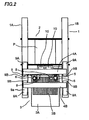
- An electronic component mounting apparatus 1 is provided with a carrying device 2 carrying a printed board P, a component feeding device 3 supplying electronic components, a pair of beams 4A and 4B movable in one direction by drive sources, and mounting heads 6 each having suction nozzles 5 and movable along the beams 4A and 4B by drive sources respectively.
- the carrying device 2 is disposed in the middle portion of the electronic component mounting apparatus 1, and has a board supply portion receiving a printed board P from an upstream device, a positioning portion positioning the printed board P supplied from the board supply portion for mounting electronic components held by suction by the suction nozzles 5 of the mounting heads 6, and a discharging portion receiving the printed board P on which the electronic components are mounted at the positioning portion and discharging it to a downstream device.
- the board supply portion is located at the left end of the carrying device 2 and the discharging portion is located at the right end of the carrying device 2. In other words, the printed board P is transported from left to right in the X direction.
- the component feeding device 3 is disposed on one side of the carrying device 2, for example, on the front side of the carrying device 2, and has a feeder base 3A mounted on the body of the electronic component mounting apparatus 1 and a group of component feeding units 3B arrayed on this feeder base 3A and supplying various electronic components to those component pickup portions (component suction positions) one by one.
- a pair of front and rear beams 4A and 4B extending in the X direction are moved in the Y direction separately by sliders fixed to each of the beams sliding along a pair of left and right guides extending in the front to rear direction, driven by each of Y direction linear motors.
- Each of the Y direction linear motors has a pair of upper and lower stationary members fixed to a pair of left and right bases 1A and 1B therealong, and moving members 9a fixed to lower portions of attachment boards respectively provided on both the ends of each of the beams 4A and 4B.
- Each of the moving members 9a includes a moving member 9A on the outside of the beams 4A and 4B and a moving member 9B on the inside thereof, and the length of the moving member 9B in the moving direction is shorter than the length of the moving member 9A in the moving direction.
- the mounting heads 6 which move along guides in the longitudinal direction (the X direction) of the beams 4A and 4B by X direction linear motors are provided on the beams 4A and 4B on the inside respectively, and each of the X direction linear motors has a pair of front and rear stationary members fixed to each of the beams 4A and 4B and a moving member located between the stationary members which is provided on each of the mounting heads 6.
- the mounting heads 6 are provided on the beams 4A and 4B on the inside so as to face each other, and move above a printed board P on the positioning portion of the carrying device 2 or above the component pickup positions of the component feeding units 3B.
- the twelve suction nozzles 5 are provided on each of the mounting heads 6 at predetermined intervals in a circle, being pushed downward by springs, and the suction nozzles 5 in the 3 o'clock and 9 o'clock positions of each of the mounting heads 6 may pick up electronic components simultaneously from the arrayed component feeding units 3B.
- the suction nozzles 5 are vertically movable by a vertical axis motor and movable in the X and Y directions by rotating the mounting head 6 about a vertical axis by a ⁇ axis motor, having a capability of rotating about a vertical axis and moving vertically.
- a board recognition camera 8 is provided on each of the mounting heads 6, which takes an image of a positioning mark given to a positioned printed board P.
- Component recognition cameras 10 sequentially take images of electronic components picked up by suction by the suction nozzles 5.
- a printed board P is received from the upstream device (not shown) and supplied onto the supply portion of the carrying device 2, and the printed board P on the supply portion is moved to the positioning portion, positioned, and fixed.
- the beam 4B on the front side moves in the Y direction by the sliders sliding along the guides extending in the front to rear direction, driven by the Y direction linear motor, and the mounting head 6 moves in the X direction by the X direction linear motor, reaches the position above the component pickup position of the component feeding unit 3B, and lowers the suction nozzle 5 by the vertical axis motor to pick up an electronic component from the component feeding unit 3.
- the plurality of suction nozzles 5 achieve picking up the electronic components from the component feeding units 3B respectively.
- the beam 4A on the rear side moves in the Y direction by the Y direction linear motor, and simultaneously the mounting head 6 moves in the X direction by the X direction linear motor, reaches the position above the component pickup position of the component feeding unit 3B, lowers the suction nozzle 5 by the vertical axis motor, and picks up an electronic component from the component feeding unit 3.
- the corresponding Y direction linear motors and the corresponding X direction linear motors are controlled so that the mounting heads 6 of both the beams 4B and 4A do not hit against each other ( Fig. 1 ).
- the apparatus realizes not only the operation in which the mounting head 6 of the beam 4B on the front side picks up electronic components from the component feeding units 3B in the left half portion of the component feeding device 3 and the mounting head 6 of the beam 4A on the rear side picks up electronic components from the component feeding units 3B in the right half portion of the component feeding device 3 ( Fig.
- the mounting head 6 of the beam 4B on the front side picks up electronic components from the component feeding units 3B in the right half portion of the component feeding device 3 and the mounting head 6 of the beam 4A on the rear side picks up electronic components from the component feeding units 3B in the left half portion of the component feeding device 3 by moving the beam 4A and/or the beam 4B in the Y direction apart from each other to positions where both the mounting heads 6 do not hit against each other, then moving both the mounting heads 6 in the X direction, and moving the beam 4A and/or the beam 4B in the Y direction close to each other ( Fig. 2 ).
- both the beams 4B and 4A are controlled so as not to come too close in the Y direction and both the mounting heads 6 are controlled so as not to come too close in the X direction, thereby preventing the mounting heads 6 of both the beams 4B and 4A from hitting against each other.
- the suction nozzles 5 of both the mounting heads 6 are then moved upward after picking up the electronic components, and the mounting heads 6 of both the beams 4A and 4B pass the component recognition cameras 10 thereabove.
- the component recognition cameras 10 take images of the plurality of electronic components held by suction by the suction nozzles 5 of both the mounting heads 6, and a recognition processing device performs recognition processing to these images to recognize the positional shifts of the electronic components relative to the suction nozzles 5.
- the board recognition camera 8 of each of both the beams 4A and 4B is moved to above the printed board P and takes an image of a positioning mark given to a positioned printed board P, and the recognition processing device performs recognition processing to this image to recognize the position of the printed board P.
- the positional recognition result about the printed board P and each of the component recognition processing results are added to the mounting coordinate of mounting data, and each of the suction nozzles 5 mounts the electronic component on the printed board P after the correction of the positional shift.
- the suction nozzles 5 of the mounting head 6 of the beam 4A on the rear side mount the electronic components on the printed board P or during this mounting
- the suction nozzles 5 of the mounting head 6 of the beam 4B on the front side mount the electronic components on the printed board P.
- the corresponding Y direction linear motors and the corresponding X direction linear motors are controlled so that the mounting heads 6 of both the beams 4A and 4B do not hit against each other ( Fig. 3 ).
- the apparatus realizes not only the operation in which the mounting head 6 of the beam 4B on the front side mounts electronic components on the left half region of the printed board P and the mounting head 6 of the beam 4A on the rear side mounts electronic components on the right half region of the printed board P ( Fig.
- the suction nozzles 5 of the mounting head 6 the beam 4A on the rear side as well as the suction nozzles 5 of the mounting head 6 of the beam 4B on the front side pick up electronic components, and even simultaneously pick up electronic components. Furthermore, the suction nozzles 5 of the mounting head 6 of the beam 4B on the front side and the suction nozzles 5 of the mounting head 6 of the beam 4A on the rear side simultaneously mount electronic components on the printed board P.
- the invention is applicable to the case in which the component feeding devices 3 need not be provided on both the sides of the carrying device 2 respectively for reasons of types of electronic components used or a setting space. After all the electronic components are mounted on the printed board P by sequentially mounting the electronic components in this manner, the printed board P is carried from the positioning portion to the discharging portion.
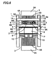
- a second embodiment will be described referring to Figs. 5 to 7 , but only a structure differing from the first embodiment will be described. While the component feeding device 3 is disposed on only one side of the carrying device 2, for example, on the front side of the carrying device 2 in the first embodiment, the component feeding devices 3 are disposed on both the sides of the carrying device 2 respectively in the second embodiment.
- the Y direction linear motors and the X direction linear motors corresponding to the beams 4A and 4B respectively are controlled so that the suction nozzles 5 of the mounting heads 6 provided on the beams 4A and 4B pick up electronic components from either of the component feeding devices 3.
- the suction nozzles 5 of the mounting head 6 provided on the beam 4A on the rear side pick up electronic components from the component feeding device 3 on the rear side and the suction nozzles 5 of the mounting head 6 provided on the beam 4B on the front side pick up electronic components from the component feeding device 3 on the front side. Furthermore, as shown in Fig. 5 , the suction nozzles 5 of the mounting head 6 provided on the beam 4A on the rear side pick up electronic components from the component feeding device 3 on the rear side and the suction nozzles 5 of the mounting head 6 provided on the beam 4B on the front side pick up electronic components from the component feeding device 3 on the front side. Furthermore, as shown in Fig.
- the suction nozzles 5 of the mounting head 6 provided on the beam 4B on the front side pick up electronic components not only from the component feeding device 3 on the front side but also from the component feeding device 3 on the rear side
- the suction nozzles 5 of the mounting head 6 provided on the beam 4A on the rear side pick up electronic components not only from the component feeding device 3 on the rear side but also from the component feeding device 3 on the front side.
- the suction nozzles 5 of the mounting heads 6 provided on the beam 4B on the front side and the beam 4A on the rear side simultaneously pick up electronic components from the component feeding device 3 on the rear side
- the suction nozzles 5 of the mounting heads 6 of both the beams 4A and 4B achieve picking up electronic components from the component feeding units 3B in both the left and right half regions of the component feeding device 3 on the rear side instead of from the left or right half region limitedly, being controlled so as not to hit against each other, by moving both the beams 4A and/or 4B apart from each other and then moving both the mounting heads 6 to the opposite sides, as described above.
- the suction nozzles 5 of the mounting heads 6 of both the beams 4A and 4B achieve mounting the electronic components on all the regions of the printed board P instead of on the left or right half region limitedly, being controlled so as not to hit against each other, by moving both the beams 4A and/or 4B apart from each other and then moving both the mounting heads 6 to the opposite sides, as described above.
- a third embodiment will be described referring to Fig. 8 , but only a structure differing from the first embodiment will be described. While in the first embodiment the component feeding device 3 is disposed on only one side of the carrying device 2 and electronic components are mounted on one printed board P on the positioning portion of the carrying device 2 by the suction nozzles 5 of the mounting heads 6 of both the beams 4A and 4B, two printed boards P are provided on the carrying device 2 in the third embodiment.
- the third embodiment is the same as the first embodiment in that the suction nozzles 5 of the beam 4B on the front side and the suction nozzles 5 of the beam 4A on the rear side pick up electronic components simultaneously and even pick up electronic components from any regions of the component feeding device 3.
- the suction nozzles 5 of the beam 4B on the front side mount the electronic components on the left printed board P and the suction nozzles 5 of the beam 4A on the rear side mount the electronic components on the right printed board P.
- the suction nozzles 5 of both the beams 4B and 4A may perform the mounting operations simultaneously.
- the suction nozzles 5 of the beams 4A and 4B may also mount the electronic components on the opposite left and right printed boards P. In both the described cases, the suction nozzles 5 of the mounting heads 6 of both the beams 4A and 4B are controlled so as not to hit against each other.
- a fourth embodiment will be described referring to Fig. 9 , but only a structure differing from the first embodiment will be described. While in the first embodiment the component feeding device 3 is disposed on only one side of the carrying device 2 and electronic components are mounted on one printed board P on the positioning portion of the carrying device 2 by the suction nozzles 5 of the mounting heads 6 of both the beams 4A and 4B, two printed boards P are provided on each of two carrying devices 2 in the fourth embodiment.
- the fourth embodiment is the same as the first embodiment in that the suction nozzles 5 of the beam 4B on the front side and the suction nozzles 5 of the beam 4A on the rear side pick up electronic components simultaneously and even pick up electronic components from any regions of the component feeding device 3.
- the suction nozzles 5 of the beam 4B on the front side mount the electronic components on the left printed board P on the carrying device 2 on the front side and the suction nozzles 5 of the beam 4A on the rear side mount the electronic components on the right printed board P on the carrying device 2 on the front side.
- the suction nozzles 5 of both the beams 4B and 4A may perform the mounting operations simultaneously.
- the suction nozzles 5 of the beams 4A and 4B may also mount the electronic components on the opposite left and right printed boards P on the carrying device 2 on the front side.
- the suction nozzles 5 of the mounting heads 6 of both the beams 4A and 4B are controlled so as not to hit against each other.
- Another two printed boards P are already positioned on the positioning portions of the carrying device 2 on the rear side, respectively. Therefore, after completing the mounting of the electronic components on the two printed boards P on the carrying device 2 on the front side, the suction nozzles 5 of the beam 4B on the front side mount the electronic components on the left printed board P on the carrying device 2 on the rear side and the suction nozzles 5 of the beam 4A on the rear side mount the electronic components on the right printed board P on the carrying device 2 on the rear side. At this time, the suction nozzles 5 of both the beams 4A and 4B may perform the mounting operations simultaneously.
- the suction nozzles 5 of the beams 4A and 4B may also mount the electronic components on the opposite left and right printed boards P on the carrying device 2 on the rear side.
- the suction nozzles 5 of the mounting heads 6 of both the beams 4A and 4B are controlled so as not to hit against each other.
- the invention is not limited to this.
- One printed board P may be positioned on each of the carrying devices 2 and electronic components may be mounted thereon.
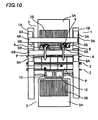
- a fifth embodiment will be described referring to Fig. 10 , but only a structure differing from the first embodiment will be described. While in the first embodiment the component feeding device 3 is disposed on only one side of the carrying device 2, for example, on the front side of the carrying device 2, the component feeding devices 3 are disposed on both the sides of the carrying device 2 respectively and two printed boards P are provided on each of two carrying devices 2 in the fifth embodiment.
- the Y direction linear motors and the X direction linear motors corresponding to the beams 4A and 4B respectively are controlled so that the suction nozzles 5 of the mounting heads 6 the beams 4A and 4B pick up electronic components from either of the component feeding devices 3.
- the suction nozzles 5 of the mounting head 6 provided on the beam 4A on the rear side pick up electronic components from the component feeding device 3 on the rear side and the suction nozzles 5 of the mounting head 6 provided on the beam 4B on the front side pick up electronic components from the component feeding device 3 on the front side. Furthermore, as shown in Fig.
- the suction nozzles 5 of the mounting head 6 provided on the beam 4B on the front side pick up electronic components not only from the component feeding device 3 on the front side but also from the component feeding device 3 on the rear side
- the suction nozzles 5 of the mounting head 6 provided on the beam 4A on the rear side pick up electronic components not only from the component feeding device 3 on the rear side but also from the component feeding device 3 on the front side.
- the suction nozzles 5 of the mounting heads 6 provided on the beam 4B on the front side and the beam 4A on the rear side simultaneously pick up electronic components from the component feeding device 3 on the rear side
- the suction nozzles 5 of the mounting heads 6 of both the beams 4A and 4B achieve picking up electronic components from the component feeding units 3B in both the left and right half regions of the component feeding device 3 on the rear side instead of from the left or right half region limitedly, being controlled so as not to hit against each other, by moving both the beams 4A and/or 4B apart from each other and then moving both the mounting heads 6 to the opposite sides, as described above.
- the suction nozzles 5 of the beam 4B on the front side mount the electronic components on the left printed board P on the carrying device 2 on the rear side and the suction nozzles 5 of the beam 4A on the rear side mount the electronic components on the right printed board P on the carrying device 2 on the rear side.
- the suction nozzles 5 of both the beams 4B and 4A may perform the mounting operations simultaneously.
- the suction nozzles 5 of the beams 4A and 4B may also mount the electronic components on the opposite left and right printed boards P on the carrying device 2 on the rear side.
- the suction nozzles 5 of the mounting heads 6 of both the beams 4A and 4B are controlled so as not to hit against each other.
- the suction nozzles 5 of the beam 4B on the front side mount the electronic components on the left printed board P on the carrying device 2 on the front side and the suction nozzles 5 of the beam 4A on the rear side mount the electronic components on the right printed board P on the carrying device 2 on the front side.
- the suction nozzles 5 of both the beams 4A and 4B may perform the mounting operations simultaneously.
- the suction nozzles 5 of the beams 4A and 4B may also mount the electronic components on the opposite left and right printed boards P on the carrying device 2 on the front side.
- the suction nozzles 5 of the mounting heads 6 of both the beams 4A and 4B are controlled so as not to hit against each other.
- the invention is not limited to this.
- One printed board P may be positioned on each of the carrying devices 2 and electronic components may be mounted thereon.
- the sixth embodiment has a tray feeder 30 and component feeding units 3B arrayed on a feeder base 3A as the component feeding devices provided on the rear side of the carrying device 2, and one printed board P is positioned on the positioning portion of the carrying device 2.
- the tray feeder 30 has, for example, a magazine 30C storing plural stages of palettes 30B on which the trays 30A having numerous arrayed electronic components are mounted, a drawing mechanism drawing the predetermined palette 30B of this magazine 30C, and an elevator mechanism lifting up the palette 30B drawn by this drawing mechanism to the electronic component supply position.
- a magazine 30C storing plural stages of palettes 30B on which the trays 30A having numerous arrayed electronic components are mounted
- a drawing mechanism drawing the predetermined palette 30B of this magazine 30C
- an elevator mechanism lifting up the palette 30B drawn by this drawing mechanism to the electronic component supply position.
- the invention is not limited to this, and any component feeding device may be used as long as it supplies electronic components with the tray 30A.
- the Y direction linear motors and the X direction linear motors corresponding to the beams 4A and 4B respectively are controlled so that the suction nozzles 5 of the mounting heads 6 provided on the beams 4A and 4B pick up electronic components from either of the component feeding devices 3.
- the suction nozzles 5 of the mounting head 6 provided on the beam 4A on the rear side pick up electronic components from the component feeding device 3 on the rear side and the suction nozzles 5 of the mounting head 6 provided on the beam 4B on the front side pick up electronic components from the component feeding device 3 on the front side. Furthermore, as shown in Fig.
- the suction nozzles 5 of the mounting head 6 provided on the beam 4A on the rear side pick up electronic components not only from the component feeding device 3 on the rear side but also from the component feeding device 3 on the front side
- the suction nozzles 5 of the mounting head 6 provided on the beam 4B on the front side pick up electronic components not only from the component feeding device 3 on the front side but also from the component feeding device 3 on the rear side.
- the suction nozzles 5 of the mounting heads 6 provided on the beam 4B on the front side and the beam 4A on the rear side simultaneously pick up electronic components from the component feeding device 3 on the front side
- the suction nozzles 5 of the mounting heads 6 of both the beams 4A and 4B achieve picking up electronic components from the component feeding units 3B in both the left and right half regions of the component feeding device 3 on the front side instead of from the left or right half region limitedly, being controlled so as not to hit against each other, by moving both the beams 4A and/or 4B apart from each other and then moving both the mounting heads 6 to the opposite sides, as described above.
- the suction nozzles 5 of the beam 4B on the front side mount the electronic components on the left half region of the printed board P on the carrying device 2 and the suction nozzles 5 of the beam 4A on the rear side mount the electronic components on the right half region of the printed board P on the carrying device 2.
- the suction nozzles 5 of both the beams 4B and 4A may perform the mounting operations simultaneously.
- the suction nozzles 5 of the beams 4A and 4B may also mount the electronic components on the opposite left and right half regions of the printed board P on the carrying device 2. In both the described cases, the suction nozzles 5 of the mounting heads 6 of both the beams 4A and 4B are controlled so as not to hit against each other.
- the invention is not limited to this.
- Two printed boards P may be positioned on the carrying device 2 and electronic components may be mounted thereon, or two carrying devices 2 may be provided, one or two printed board P may be positioned on each of the devices 2 and electronic components may be mounted thereon.
- the component feeding devices 3 are provided on both the sides of the carrying device 2 respectively, particularly when the tray feeder 30 having electronic components on the tray 30A for picking up the electronic components by the suction nozzles 5 is used as one of the component feeding devices 3, conventionally the operating rate of the corresponding beam 4A on the rear side is decreased and the production efficiency is low when the frequency of picking up electronic components from this tray feeder 30 is low.
- the beam 4A on the rear side achieve picking up electronic components from the component feeding device 3 on the front side, as described above, the operating rates of both the beams 4A and 4B are increased and the production efficiency is enhanced.
- the invention provides an electronic component mounting apparatus which increases the operating rate of the beam to enhance the production efficiency.
- the invention also provides an electronic component mounting apparatus which is applicable to the case in which the component feeding device is provided on one side of the carrying device as well as the case in which the component feeding device are provided on both sides of the carrying device respectively for reasons of types of electronic components or a setting space.
Landscapes
- Engineering & Computer Science (AREA)
- Manufacturing & Machinery (AREA)
- Microelectronics & Electronic Packaging (AREA)
- Supply And Installment Of Electrical Components (AREA)
Applications Claiming Priority (1)
| Application Number | Priority Date | Filing Date | Title |
|---|---|---|---|
| JP2007117763A JP4846649B2 (ja) | 2007-04-26 | 2007-04-26 | 電子部品装着装置 |
Publications (3)
| Publication Number | Publication Date |
|---|---|
| EP1986484A2 true EP1986484A2 (fr) | 2008-10-29 |
| EP1986484A3 EP1986484A3 (fr) | 2011-03-30 |
| EP1986484B1 EP1986484B1 (fr) | 2015-10-14 |
Family
ID=39616579
Family Applications (1)
| Application Number | Title | Priority Date | Filing Date |
|---|---|---|---|
| EP08008102.9A Active EP1986484B1 (fr) | 2007-04-26 | 2008-04-28 | Appareil de montage de composant électronique |
Country Status (5)
| Country | Link |
|---|---|
| US (2) | US7841073B2 (fr) |
| EP (1) | EP1986484B1 (fr) |
| JP (1) | JP4846649B2 (fr) |
| KR (3) | KR101177964B1 (fr) |
| CN (1) | CN101299915B (fr) |
Cited By (1)
| Publication number | Priority date | Publication date | Assignee | Title |
|---|---|---|---|---|
| FR3025398A1 (fr) * | 2014-08-28 | 2016-03-04 | Europlacer Ind | Machine de report de composants electroniques sur cartes electroniques a plusieurs tetes de report |
Families Citing this family (11)
| Publication number | Priority date | Publication date | Assignee | Title |
|---|---|---|---|---|
| JP5103238B2 (ja) * | 2008-03-25 | 2012-12-19 | 株式会社日立ハイテクインスツルメンツ | 電子部品装着装置 |
| JP5342159B2 (ja) * | 2008-03-25 | 2013-11-13 | 株式会社日立ハイテクインスツルメンツ | 電子部品装着装置 |
| JP5096385B2 (ja) * | 2009-01-29 | 2012-12-12 | 株式会社日立ハイテクインスツルメンツ | 電子部品装着装置 |
| JP4760940B2 (ja) * | 2009-03-25 | 2011-08-31 | パナソニック株式会社 | 電子部品実装装置 |
| JP5317856B2 (ja) * | 2009-06-30 | 2013-10-16 | 株式会社日立ハイテクインスツルメンツ | 電子部品装着装置 |
| DE102009042651B4 (de) * | 2009-09-23 | 2012-01-19 | Asm Assembly Systems Gmbh & Co. Kg | Vefahren zum Bestücken von Substraten mit Bauelementen |
| JP5773474B2 (ja) * | 2010-05-20 | 2015-09-02 | 富士機械製造株式会社 | 部品実装システム |
| JP2012195508A (ja) * | 2011-03-17 | 2012-10-11 | Juki Corp | 電子部品実装装置 |
| DE102014117026B3 (de) * | 2014-11-20 | 2015-12-03 | Strothmann Machines & Handling GmbH | Transfervorrichtung |
| SG11202013223TA (en) * | 2018-07-24 | 2021-01-28 | Shinkawa Kk | Electronic component mounting apparatus |
| CN113102979B (zh) * | 2021-04-23 | 2022-04-05 | 无锡国盛生物工程有限公司 | 一种吸头滤芯安装装置 |
Citations (2)
| Publication number | Priority date | Publication date | Assignee | Title |
|---|---|---|---|---|
| JP2006286707A (ja) | 2005-03-31 | 2006-10-19 | Hitachi High-Tech Instruments Co Ltd | 電子部品の装着方法及び電子部品の装着装置 |
| JP2007117763A (ja) | 2007-02-08 | 2007-05-17 | Kyoraku Sangyo Kk | パチンコ遊技機 |
Family Cites Families (10)
| Publication number | Priority date | Publication date | Assignee | Title |
|---|---|---|---|---|
| JP2767415B2 (ja) * | 1997-01-27 | 1998-06-18 | ヤマハ発動機株式会社 | チップ部品装着装置 |
| WO2000078114A1 (fr) * | 1999-06-16 | 2000-12-21 | Koninklijke Philips Electronics N.V. | Machine de montage de composants |
| JP3960054B2 (ja) * | 2002-01-21 | 2007-08-15 | 松下電器産業株式会社 | 電子部品実装装置および電子部品の実装ヘッドユニット |
| JP2004128400A (ja) * | 2002-10-07 | 2004-04-22 | Fuji Mach Mfg Co Ltd | 部品実装装置、その作動を制御するプログラムおよび部品実装システム |
| JP4387745B2 (ja) * | 2003-09-30 | 2009-12-24 | 株式会社日立ハイテクインスツルメンツ | 電子部品装着装置 |
| US7353589B2 (en) * | 2003-10-15 | 2008-04-08 | Matsushita Electric Industrial Co., Ltd. | Component mounting apparatus |
| JP2005228992A (ja) * | 2004-02-13 | 2005-08-25 | Hitachi High-Tech Instruments Co Ltd | 電子部品装着装置 |
| JP4417779B2 (ja) * | 2004-05-31 | 2010-02-17 | 株式会社日立ハイテクインスツルメンツ | 電子部品装着装置及び電子部品装着方法 |
| JP4450772B2 (ja) * | 2005-06-30 | 2010-04-14 | 株式会社日立ハイテクインスツルメンツ | 電子部品装着装置 |
| DE102008056734B3 (de) * | 2008-11-11 | 2010-07-22 | Siemens Electronics Assembly Systems Gmbh & Co. Kg | Bestückautomat mit zwischen Bestück- und Abholbereich einbringbarer Trenneinrichtung |
-
2007
- 2007-04-26 JP JP2007117763A patent/JP4846649B2/ja active Active
-
2008
- 2008-04-25 KR KR1020080038591A patent/KR101177964B1/ko active Active
- 2008-04-25 US US12/109,647 patent/US7841073B2/en active Active
- 2008-04-28 CN CN2008100948210A patent/CN101299915B/zh active Active
- 2008-04-28 EP EP08008102.9A patent/EP1986484B1/fr active Active
-
2010
- 2010-10-21 US US12/909,607 patent/US8127435B2/en active Active
-
2011
- 2011-10-19 KR KR1020110106995A patent/KR101126501B1/ko active Active
-
2012
- 2012-05-14 KR KR1020120050827A patent/KR101193804B1/ko active Active
Patent Citations (2)
| Publication number | Priority date | Publication date | Assignee | Title |
|---|---|---|---|---|
| JP2006286707A (ja) | 2005-03-31 | 2006-10-19 | Hitachi High-Tech Instruments Co Ltd | 電子部品の装着方法及び電子部品の装着装置 |
| JP2007117763A (ja) | 2007-02-08 | 2007-05-17 | Kyoraku Sangyo Kk | パチンコ遊技機 |
Cited By (1)
| Publication number | Priority date | Publication date | Assignee | Title |
|---|---|---|---|---|
| FR3025398A1 (fr) * | 2014-08-28 | 2016-03-04 | Europlacer Ind | Machine de report de composants electroniques sur cartes electroniques a plusieurs tetes de report |
Also Published As
| Publication number | Publication date |
|---|---|
| EP1986484A3 (fr) | 2011-03-30 |
| KR101193804B1 (ko) | 2012-10-23 |
| JP4846649B2 (ja) | 2011-12-28 |
| EP1986484B1 (fr) | 2015-10-14 |
| KR20080096439A (ko) | 2008-10-30 |
| KR101177964B1 (ko) | 2012-08-28 |
| CN101299915A (zh) | 2008-11-05 |
| US20080263857A1 (en) | 2008-10-30 |
| JP2008277452A (ja) | 2008-11-13 |
| CN101299915B (zh) | 2012-05-30 |
| KR20120073165A (ko) | 2012-07-04 |
| US7841073B2 (en) | 2010-11-30 |
| US20110030203A1 (en) | 2011-02-10 |
| US8127435B2 (en) | 2012-03-06 |
| KR20110118609A (ko) | 2011-10-31 |
| KR101126501B1 (ko) | 2012-03-29 |
Similar Documents
| Publication | Publication Date | Title |
|---|---|---|
| EP1986484B1 (fr) | Appareil de montage de composant électronique | |
| US8376129B2 (en) | Component mounting apparatus, mounting-component producing method, and conveyor apparatus | |
| US8505194B2 (en) | Apparatus of mounting component | |
| KR20120112068A (ko) | 부품 실장 장치, 정보 처리 장치, 정보 처리 방법 및 기판 제조 방법 | |
| US9854684B2 (en) | Component mounting machine | |
| KR100954936B1 (ko) | 전자 부품 장착 장치 | |
| EP2182790A2 (fr) | Procédé d'assemblage de composant électronique et appareil d'assemblage de composant électronique | |
| EP3062339A1 (fr) | Appareil d'usinage de substrat | |
| JP2006080158A (ja) | 表面実装装置 | |
| EP3806611B1 (fr) | Dispositif de détermination, dispositif de montage de composant doté de celui-ci, et procédé de détermination | |
| EP1622441A2 (fr) | Appareil de montage de composant électronique | |
| JP2006310647A (ja) | 表面実装機および部品実装方法 | |
| JP4387825B2 (ja) | 電子部品装着装置 | |
| JP6025137B2 (ja) | 基板搬送装置、部品実装装置、基板搬送方法、及び基板の製造方法 | |
| JP4933508B2 (ja) | 電子部品の装着方法 | |
| JP2009246261A (ja) | 電子部品の装着方法 | |
| JP2005203393A (ja) | 電子部品装着装置 | |
| JP2005116904A (ja) | 電子部品実装方法 | |
| JP2005285839A (ja) | 部品搬送装置、表面実装機および部品試験装置 | |
| JP2006049545A (ja) | 電子部品の装着方法 |
Legal Events
| Date | Code | Title | Description |
|---|---|---|---|
| PUAI | Public reference made under article 153(3) epc to a published international application that has entered the european phase |
Free format text: ORIGINAL CODE: 0009012 |
|
| AK | Designated contracting states |
Kind code of ref document: A2 Designated state(s): AT BE BG CH CY CZ DE DK EE ES FI FR GB GR HR HU IE IS IT LI LT LU LV MC MT NL NO PL PT RO SE SI SK TR |
|
| AX | Request for extension of the european patent |
Extension state: AL BA MK RS |
|
| PUAL | Search report despatched |
Free format text: ORIGINAL CODE: 0009013 |
|
| AK | Designated contracting states |
Kind code of ref document: A3 Designated state(s): AT BE BG CH CY CZ DE DK EE ES FI FR GB GR HR HU IE IS IT LI LT LU LV MC MT NL NO PL PT RO SE SI SK TR |
|
| AX | Request for extension of the european patent |
Extension state: AL BA MK RS |
|
| 17P | Request for examination filed |
Effective date: 20110929 |
|
| AKX | Designation fees paid |
Designated state(s): DE NL |
|
| 17Q | First examination report despatched |
Effective date: 20120119 |
|
| RAP1 | Party data changed (applicant data changed or rights of an application transferred) |
Owner name: YAMAHA HATSUDOKI KABUSHIKI KAISHA |
|
| GRAP | Despatch of communication of intention to grant a patent |
Free format text: ORIGINAL CODE: EPIDOSNIGR1 |
|
| INTG | Intention to grant announced |
Effective date: 20150616 |
|
| RIN1 | Information on inventor provided before grant (corrected) |
Inventor name: MITSUMOCHI, YUTAKA Inventor name: KASHITANI, HISAYOSHI Inventor name: IZUHARA, KOICHI Inventor name: ONOGUCHI, YOSHIHIRO Inventor name: IIZUKA, MASAMI Inventor name: KOBAYASHI, HIROOMI Inventor name: OYAMA, KAZUYOSHI |
|
| GRAS | Grant fee paid |
Free format text: ORIGINAL CODE: EPIDOSNIGR3 |
|
| GRAA | (expected) grant |
Free format text: ORIGINAL CODE: 0009210 |
|
| AK | Designated contracting states |
Kind code of ref document: B1 Designated state(s): DE NL |
|
| REG | Reference to a national code |
Ref country code: DE Ref legal event code: R096 Ref document number: 602008040607 Country of ref document: DE |
|
| REG | Reference to a national code |
Ref country code: NL Ref legal event code: MP Effective date: 20151014 |
|
| PG25 | Lapsed in a contracting state [announced via postgrant information from national office to epo] |
Ref country code: NL Free format text: LAPSE BECAUSE OF FAILURE TO SUBMIT A TRANSLATION OF THE DESCRIPTION OR TO PAY THE FEE WITHIN THE PRESCRIBED TIME-LIMIT Effective date: 20151014 |
|
| REG | Reference to a national code |
Ref country code: DE Ref legal event code: R097 Ref document number: 602008040607 Country of ref document: DE |
|
| PLBE | No opposition filed within time limit |
Free format text: ORIGINAL CODE: 0009261 |
|
| STAA | Information on the status of an ep patent application or granted ep patent |
Free format text: STATUS: NO OPPOSITION FILED WITHIN TIME LIMIT |
|
| 26N | No opposition filed |
Effective date: 20160715 |
|
| PGFP | Annual fee paid to national office [announced via postgrant information from national office to epo] |
Ref country code: DE Payment date: 20250422 Year of fee payment: 18 |