EP1987272B1 - Joint d'etancheite a canal pour tete de cylindre - Google Patents
Joint d'etancheite a canal pour tete de cylindre Download PDFInfo
- Publication number
- EP1987272B1 EP1987272B1 EP07702871A EP07702871A EP1987272B1 EP 1987272 B1 EP1987272 B1 EP 1987272B1 EP 07702871 A EP07702871 A EP 07702871A EP 07702871 A EP07702871 A EP 07702871A EP 1987272 B1 EP1987272 B1 EP 1987272B1
- Authority
- EP
- European Patent Office
- Prior art keywords
- cylinder head
- sealing
- channel
- gasket
- head gasket
- Prior art date
- Legal status (The legal status is an assumption and is not a legal conclusion. Google has not performed a legal analysis and makes no representation as to the accuracy of the status listed.)
- Not-in-force
Links
Images

Classifications
-
- F—MECHANICAL ENGINEERING; LIGHTING; HEATING; WEAPONS; BLASTING
- F16—ENGINEERING ELEMENTS AND UNITS; GENERAL MEASURES FOR PRODUCING AND MAINTAINING EFFECTIVE FUNCTIONING OF MACHINES OR INSTALLATIONS; THERMAL INSULATION IN GENERAL
- F16J—PISTONS; CYLINDERS; SEALINGS
- F16J15/00—Sealings
- F16J15/02—Sealings between relatively-stationary surfaces
- F16J15/06—Sealings between relatively-stationary surfaces with solid packing compressed between sealing surfaces
- F16J15/064—Sealings between relatively-stationary surfaces with solid packing compressed between sealing surfaces the packing combining the sealing function with other functions
-
- F—MECHANICAL ENGINEERING; LIGHTING; HEATING; WEAPONS; BLASTING
- F02—COMBUSTION ENGINES; HOT-GAS OR COMBUSTION-PRODUCT ENGINE PLANTS
- F02F—CYLINDERS, PISTONS OR CASINGS, FOR COMBUSTION ENGINES; ARRANGEMENTS OF SEALINGS IN COMBUSTION ENGINES
- F02F11/00—Arrangements of sealings in combustion engines
- F02F11/002—Arrangements of sealings in combustion engines involving cylinder heads
-
- F—MECHANICAL ENGINEERING; LIGHTING; HEATING; WEAPONS; BLASTING
- F16—ENGINEERING ELEMENTS AND UNITS; GENERAL MEASURES FOR PRODUCING AND MAINTAINING EFFECTIVE FUNCTIONING OF MACHINES OR INSTALLATIONS; THERMAL INSULATION IN GENERAL
- F16J—PISTONS; CYLINDERS; SEALINGS
- F16J15/00—Sealings
- F16J15/02—Sealings between relatively-stationary surfaces
- F16J15/06—Sealings between relatively-stationary surfaces with solid packing compressed between sealing surfaces
- F16J15/08—Sealings between relatively-stationary surfaces with solid packing compressed between sealing surfaces with exclusively metal packing
- F16J15/0818—Flat gaskets
-
- F—MECHANICAL ENGINEERING; LIGHTING; HEATING; WEAPONS; BLASTING
- F16—ENGINEERING ELEMENTS AND UNITS; GENERAL MEASURES FOR PRODUCING AND MAINTAINING EFFECTIVE FUNCTIONING OF MACHINES OR INSTALLATIONS; THERMAL INSULATION IN GENERAL
- F16J—PISTONS; CYLINDERS; SEALINGS
- F16J15/00—Sealings
- F16J15/02—Sealings between relatively-stationary surfaces
- F16J15/06—Sealings between relatively-stationary surfaces with solid packing compressed between sealing surfaces
- F16J15/08—Sealings between relatively-stationary surfaces with solid packing compressed between sealing surfaces with exclusively metal packing
- F16J15/0818—Flat gaskets
- F16J15/0825—Flat gaskets laminated
-
- F—MECHANICAL ENGINEERING; LIGHTING; HEATING; WEAPONS; BLASTING
- F16—ENGINEERING ELEMENTS AND UNITS; GENERAL MEASURES FOR PRODUCING AND MAINTAINING EFFECTIVE FUNCTIONING OF MACHINES OR INSTALLATIONS; THERMAL INSULATION IN GENERAL
- F16J—PISTONS; CYLINDERS; SEALINGS
- F16J15/00—Sealings
- F16J15/02—Sealings between relatively-stationary surfaces
- F16J15/06—Sealings between relatively-stationary surfaces with solid packing compressed between sealing surfaces
- F16J15/08—Sealings between relatively-stationary surfaces with solid packing compressed between sealing surfaces with exclusively metal packing
- F16J15/0818—Flat gaskets
- F16J2015/0856—Flat gaskets with a non-metallic coating or strip
-
- F—MECHANICAL ENGINEERING; LIGHTING; HEATING; WEAPONS; BLASTING
- F16—ENGINEERING ELEMENTS AND UNITS; GENERAL MEASURES FOR PRODUCING AND MAINTAINING EFFECTIVE FUNCTIONING OF MACHINES OR INSTALLATIONS; THERMAL INSULATION IN GENERAL
- F16J—PISTONS; CYLINDERS; SEALINGS
- F16J15/00—Sealings
- F16J15/02—Sealings between relatively-stationary surfaces
- F16J15/06—Sealings between relatively-stationary surfaces with solid packing compressed between sealing surfaces
- F16J15/08—Sealings between relatively-stationary surfaces with solid packing compressed between sealing surfaces with exclusively metal packing
- F16J15/0818—Flat gaskets
- F16J2015/0868—Aspects not related to the edges of the gasket
Definitions
- the present invention relates to a metal-elastomeric gasket, and more particularly to a cylinder head gasket suitable for use in internal combustion engines.
- the cylinder head gasket has, in addition to one or more metal gaskets, at least one combustion chamber seal and an elastomeric gasket that runs around the combustion chamber gasket.
- cooling liquid is passed to dissipate the heat generated between the engine block and the cylinder head.
- a degassing is to be made possible, so that a derivative of remaining in the system air and / or gas in a fluid flow between the engine block, cylinder head gasket cylinder head is made possible.
- a sealing function in at least one of the layers of such a flat gasket, which generally completely surrounds these through-openings. Due to the sealing function, usually a bead or an elastomer profile, a corresponding sealing line is then produced.
- one or more beads for sealing high-pressure regions for example a combustion chamber, and elastomer profiles for sealing low-pressure regions, for example cooling-fluid flows or for protecting the engine block against weather-related environmental influences, are usually used.
- Such metal seals with bead or elastomeric profile are usually used for sealing combustion chambers of a corresponding engine and in particular as a cylinder head gaskets.
- metal gaskets have prevailed, which often consist of several layers and preferably of steel wherein the required elasticity is produced in that at least one of the layers has a bead surrounding the combustion chamber passage opening.
- the cylinder head gaskets are increasingly made predominantly of aluminum and the cylinder block predominantly of magnesium.
- the cylinder head gasket receiving sealing gap between the engine block and cylinder head Since during operation of an internal combustion engine, the width or width of the cylinder head gasket receiving sealing gap between the engine block and cylinder head periodically changes depending on the power stroke of each considered cylinder, the cylinder head gasket is subject to constant pressure changes in engine operation.
- the seal around a combustion chamber opening around at least substantially by a combustion chamber opening enclosing sealing bead which must have permanently resilient properties to maintain a perfect seal because of the above-described sealing gap changes, that is, the sealing bead must still after a long time Engine operating time in the direction perpendicular to the sealing plate plane be elastically deformable. The same applies to a lesser extent to the elastomer profiles used to seal the low pressure area.
- cylinder head gaskets are used in today's internal combustion engines, in which so-called full corrugations embossed in spring steel are used for permanently elastic combustion chamber sealing.
- Full beads are characterized in that, starting from a base surface of the sheet, an elevation is formed in one direction, so that a contact line (beading comb) is formed to the base surface side facing away from as a sealing line.
- Full corrugations are always based in the plane of the base area with so-called bead feet arranged on both sides of the percolating comb, i. in the plane of the base area, two sealing lines are formed. This basic construction of a full bead requires a minimum amount of space in the cross section and must be formed by relatively complex embossing tools.
- a seal which includes a made of a soft steel metal core, in the region of both sealing surfaces completely with a Elastomer layer is provided.
- the metal core breakthroughs and, if necessary, also bends.
- the elastomeric material is cold applied to the associated surface and cured in a heated mold prior to vulcanization.
- the elastomeric material profiles are introduced, which have a triangular cross-section.
- the DE4438879 relates to a single or multi-layer metallic cylinder head gasket for internal combustion engines with precombustion chamber, wherein a Vorverbrennungshunt having the component is installed in the cylinder head and rests in the mounted state of the seal with a bottom surface on the gasket, and at least one running outside the bottom surface, the combustion chamber opening enclosing bead ,
- the bead is further preceded by an arcuate slot in the region of the outer edge of the component, so that the heat transfer is prevented in this area from the component to the bead.
- DE4215217 A1 discloses a cylinder head gasket, wherein the liquid openings are surrounded on both sides by elastomeric pads.
- the cylinder head gaskets described in the above prior art all have the disadvantage that during operation of the engine block with cooling fluid, corresponding air remains in the system and can not be removed.
- air may form in the form of small air bubbles in a bore of the engine block and attach to the metallic seal, which can lead to their corrosion.
- hot combustion gases can escape from a possibly defective combustion chamber seal and in turn lead to the corrosion of metallic materials.
- Another object of the present invention is to prevent the entry of gases, particularly hot combustion gases, into undesirable areas of the engine block.
- the above objects have been achieved by providing the cylinder head gasket according to the invention.
- the cylinder head gasket essentially comprises one or more metallic gasket layers and one or more combustion chamber seals suitable for sealing the high-pressure region.
- the term high-pressure area relates in this case to the area enclosed by a combustion chamber seal.
- an elastomer seal suitable for sealing a low pressure region is preferably arranged around the combustion chamber seal (s).
- the plane of the cylinder head gasket in at least one of the gasket layers has a channel which ensures a targeted discharge of the gases and / or air through this coolant opening.
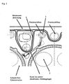
- a cylinder head gasket which comprises at least one metal sealing layer 1, at least one combustion chamber seal, openings 2 around the combustion chambers and an elastomeric seal extending around the combustion chamber seal (s).
- the cylinder head gasket further comprises at least one channel 4, which runs in the plane of the cylinder head gasket in at least one sealing layer and which intersects a fluid opening 3.
- the cylinder head gasket is further characterized in that the seal in the region of the openings acts as a diaphragm (6), and the channel is formed of elastomeric material.
- the production of metallic gaskets is well known to those skilled in the art and can be performed according to the respective specifications and requirements by, for example, a CNC machine.
- the metallic gasket layer can be produced, for example, by folding or pressing the respective metal, for example from different steels or magnesium.
- the combustion chamber seal sealingly encloses a high pressure region, such as a cylinder or cylinder liner, to prevent escape of the combustion gases.
- the sealing of the combustion chamber takes place for example by means of one or more beads in at least one of the metallic gasket layer (s).
- the formation of beads is known in the art and includes, for example, corresponding folding or pressing of the metal of the gasket layer (s).
- an elastomeric seal for example consisting of silicones, fluorosilicone, fluoroelastomers, fluorothermoplasts, polyetheretherketones (PEEK), polyphenylene sulfide (PSU), polyamide-imide (PAI) and self-reinforced liquid crystalline polymers (LCP).
- the elastomer is applied in the form of a coating on at least one sealing layer, wherein the sealing layer is provided with one or more embossing regions receiving the elastomeric material.
- the preparation of the embossing range can be done for example by folding or pressing the gasket layer material.
- liquid elastomer molding (LEM) method for applying the elastomeric material in the embossing area, for example, the so-called liquid elastomer molding (LEM) method is used, which in the US-B 6,530,575 is described.
- LEM liquid elastomer molding
- Other methods of applying the Elastomer coating are known from the prior art. Suitable here is the screen printing, in which the material itself or dispersions of the material are applied.
- an injection molding process for applying the elastomer coating is well suited.
- the coolant opening 3, in which the at least one channel 4 opens in this case represents a low pressure region and allows a discharge of possibly accumulated gases and / or air from the engine block, without any distribution takes place.
- the opening 3 of the fluid flow may be partially (with the exception of the inflowing channel) provided with a suitable sealant for sealing on one or more sides, such as an elastomeric seal.
- a suitable sealant for sealing on one or more sides, such as an elastomeric seal.
- gases and / or air may arise which adversely affect the operation of the engine.
- air may be present in the area at the same time as the air is introduced and lead to deposits on the seals and leaks in the elastomer seal or the combustion chamber seal during later operation of the engine.
- the at least one channel 4 formed in the region By means of the at least one channel 4 formed in the region, a possibility for discharging these gases and / or air via the opening 3 of a fluid flow is now provided in the present invention.
- the advantage here is further that in case of leaks in the combustion chamber sealing emerging hot combustion gases do not accumulate in the plane of the cylinder head gasket and damage sealant or metallic components, but also targeted are derived in a range in which no adverse effects can occur.
- Such a channel or channels may be formed by methods known to those skilled in the art, including stamping, milling, embossing, or a combination of these methods, in the plane of the art Cylinder head gasket to be produced in at least one gasket layer.
- the at least one channel 4 is formed in the plane of the cylinder head gasket so that no impairment of the sealing function of the combustion chamber seal occurs, ie, that the channel is formed at a sufficient distance from the gasket to ensure proper operation thereof guarantee.
- one end of the at least one channel intersects a fluid hole 5 of the engine block underlying it in operation and thus creates a connection between, for example, two fluid ports, thereby also enabling improved degasification.
- the opening 3 is a coolant flow.
- corresponding coolant are water and / or oil, for which holes are already present in the engine block and the cylinder head.
- an already existing water flow is used as an end point of the at least one channel.
- the at least one channel 4 is punched, milled and / or stamped into the gasket layer of metal. Corresponding methods for this are known to the person skilled in the art and can also be combined if necessary.
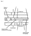
- an elastomeric material is applied on both sides of the gasket layer 1 of metal, which forms the channel 4 by a recess provided in the elastomeric material or groove.
- This allows the fluid to flow along the in Fig. 3 Thus, for example, from the fluid hole 5 to the fluid port 3.
- the seal thus acts in the region of the openings or holes like a diaphragm 6, which together with the channel 4 forms a flow path for the fluid to be passed.
- the gasket layer 1 is preferably thinned or recessed, as in Fig. 4 to see.
- the at least one metal sealing layer has a layer thickness of 0.2 to 4.0 mm, preferably 0.8 to 2.2 mm and more preferably 1.2 to 2.0 mm.
- the at least one channel or recess in the metal of the gasket layer has a depth of 0.05 to 0.5 mm and a width of 0.01 to 0.5 mm.
- Preferred dimensions of the at least one channel are a depth of 0.08 to 0.2 mm and a width of 0.01 to 0.2 mm. More preferable are a depth of 0.1 to 0.15 mm and a width of 0.1 to 0.15 mm. It should be clear in this case that the channel depth is selected as a function of the layer thickness of the gasket layer, so that the selected channel depth is always smaller than the layer thickness of the gasket layer.
- the metal may be, for example, a steel such as spring steel or stainless steel, or magnesium or aluminum.
- the metal may be favorable to choose combined layers of different metals which are known to the person skilled in the art.
- the metal is a steel such as spring steel or a stainless steel such as V4 steel.
- the at least one combustion chamber seal is formed from one or more beads.
- the seal around a combustion chamber opening around this takes place essentially by the sealing chamber opening enclosing sealing bead, which should have permanently resilient properties to maintain a perfect seal due to the above-described sealing gap changes, that is, the sealing bead must be resilient even after a long engine operating in the direction perpendicular to the sealing plate plane be deformable.
- the material of the elastomeric seal consists of silicones, fluorosilicones, fluoroelastomers, fluorothermoplasts, polyetheretherketones (PEEK), polyphenylene sulfide (PSU), polyamide-imide (PAI) and self-reinforced liquid-crystalline polymers (LCP).
- PEEK polyetheretherketones
- PSU polyphenylene sulfide
- PAI polyamide-imide
- LCP self-reinforced liquid-crystalline polymers
- the cylinder head gasket has deformation limiters arranged around the corresponding seals, elastomeric gasket and / or combustion chamber gasket.
- the deformation limiter limits the possible deformation of the respective seal, for example a sealing bead. That is, the spring travel of the bead is limited, whereby the sealing bead is protected from an impermissibly high deformation.
- a deformation limiter is also referred to as stopping.
- such a stopper has the shape of a metallic circular ring which has been applied radially outside or radially inside the sealing bead to that metal layer in which the sealing bead is formed; in the case of a multi-layered sealing plate, the stopping may also be applied to a sheet metal layer adjacent to said sheet metal layer so that it bears against the sheet layer provided with the sealing bead when the cylinder head gasket is clamped in, radially inside or radially outside this bead. From the prior art, further examples of such stopping are known, as from U.S. 5,713,580 , The design and manufacture of suitable strain limiter are well known to those skilled in the art.
- the cylinder head gasket according to the invention can be used not only in the manufacture of engines for automobiles, but also of other internal combustion engines.
- the preparation of the cylinder head gasket according to the invention can also be done with the same tools as for cylinder head gaskets according to the prior art, since only one station variant in the tool for the formation of the channel is necessary.
Landscapes
- Engineering & Computer Science (AREA)
- General Engineering & Computer Science (AREA)
- Mechanical Engineering (AREA)
- Chemical & Material Sciences (AREA)
- Combustion & Propulsion (AREA)
- Gasket Seals (AREA)
- Diaphragms For Electromechanical Transducers (AREA)
Claims (5)
- Joint de culasse, comportant :au moins une couche d'étanchéité (1) en métal,avec des orifices (2) pour les chambres de combustion ;au moins une garniture d'étanchéité de la chambre de combustion autour des orifices (2) ; etau moins un orifice (3), formé dans la couche d'étanchéité (1) en métal, pour le passage du fluide de refroidissement ;au moins un conduit (4) étant formé dans le plan du joint de culasse dans ladite au moins une couche d'étanchéité (1), lequel coupe l'orifice (3) pour le fluide de refroidissement,caractérisé en ce que
le joint dans la zone des orifices fait fonction d'obturateur (6), et
le conduit (4) est réalisé dans un matériau élastomère. - Joint de culasse selon la revendication 1, dans lequel ladite au moins une couche d'étanchéité (1) en métal possède une épaisseur de matériau de 0,2 à 4,0 mm.
- Joint de culasse selon la revendication 1 ou 2, dans lequel ledit au moins un conduit a une profondeur de 0,05 à 0,5 mm et une largeur de 0,01 à 0,5.
- Joint de culasse selon l'une quelconque des revendications précédentes, caractérisé par au moins deux couches d'étanchéité qui sont réalisées dans des métaux différents.
- Joint de culasse selon l'une quelconque des revendications précédentes, dans lequel le métal de la couche d'étanchéité (1) est l'acier.
Applications Claiming Priority (2)
| Application Number | Priority Date | Filing Date | Title |
|---|---|---|---|
| DE102006008270A DE102006008270B4 (de) | 2006-02-22 | 2006-02-22 | Zylinderkopfdichtung mit Kanal |
| PCT/EP2007/000438 WO2007096032A1 (fr) | 2006-02-22 | 2007-01-18 | Joint d'etancheite a canal pour tete de cylindre |
Publications (2)
| Publication Number | Publication Date |
|---|---|
| EP1987272A1 EP1987272A1 (fr) | 2008-11-05 |
| EP1987272B1 true EP1987272B1 (fr) | 2010-04-07 |
Family
ID=38319750
Family Applications (1)
| Application Number | Title | Priority Date | Filing Date |
|---|---|---|---|
| EP07702871A Not-in-force EP1987272B1 (fr) | 2006-02-22 | 2007-01-18 | Joint d'etancheite a canal pour tete de cylindre |
Country Status (5)
| Country | Link |
|---|---|
| US (1) | US20100007095A1 (fr) |
| EP (1) | EP1987272B1 (fr) |
| AT (1) | ATE463691T1 (fr) |
| DE (2) | DE102006008270B4 (fr) |
| WO (1) | WO2007096032A1 (fr) |
Families Citing this family (16)
| Publication number | Priority date | Publication date | Assignee | Title |
|---|---|---|---|---|
| US8245685B2 (en) | 2009-06-26 | 2012-08-21 | Ford Global Technologies | Lubrication and sealing system for internal combustion engine |
| US8261702B2 (en) | 2009-06-26 | 2012-09-11 | Ford Global Technologies | Internal combustion engine with direct cooling of cylinder components |
| DE102010002082B4 (de) | 2010-02-18 | 2013-09-19 | Ford Global Technologies, Llc | Separat gekühlter Abgassammler zur Aufrechterhaltung einer No-Flow Strategie des Zylinderblockkühlmittelmantels |
| FR2961574A1 (fr) * | 2010-06-17 | 2011-12-23 | Freudenberg Carl Kg | Joint de culasse multicouche a feuilles externes en materiau adapte |
| US8474251B2 (en) | 2010-10-19 | 2013-07-02 | Ford Global Technologies, Llc | Cylinder head cooling system |
| DE102011011103A1 (de) * | 2011-02-12 | 2012-08-16 | Elringklinger Ag | Dichtung |
| US20130269666A1 (en) * | 2011-08-12 | 2013-10-17 | Mcalister Technologies, Llc | Combustion chamber inserts and associated methods of use and manufacture |
| US8814171B2 (en) * | 2011-10-25 | 2014-08-26 | Ford Global Technologies, Llc | Engine sealing assembly |
| US8875669B2 (en) | 2012-04-27 | 2014-11-04 | Ford Global Technologies, Llc | Head gasket having variable area coolant openings |
| DE102012109646A1 (de) | 2012-10-10 | 2014-04-10 | Elringklinger Ag | Zylinderkopfdichtung |
| US9169821B2 (en) | 2012-11-02 | 2015-10-27 | Mcalister Technologies, Llc | Fuel injection systems with enhanced corona burst |
| WO2015061808A1 (fr) * | 2013-10-25 | 2015-04-30 | Mcalister Technologies, Llc | Joints de chambre de combustion et procédés d'utilisation et de fabrication associés |
| FI20146022A7 (fi) * | 2014-11-21 | 2016-05-22 | Waertsilae Finland Oy | Tiivisteasennelma käytettäväksi mäntäpolttomoottorissa, laippa-asennelma mäntäpolttomoottorissa |
| US20160222908A1 (en) * | 2015-02-04 | 2016-08-04 | GM Global Technology Operations LLC | Fluid control system and method of making and using the same |
| DE102015215083A1 (de) | 2015-08-06 | 2017-02-09 | Elringklinger Ag | Zylinderkopfdichtung |
| EP4091889B1 (fr) * | 2021-05-19 | 2024-08-28 | ZF CV Systems Europe BV | Dispositif de joint d'étanchéité pour un système de soupape pneumatique, notamment pour un véhicule utilitaire |
Family Cites Families (30)
| Publication number | Priority date | Publication date | Assignee | Title |
|---|---|---|---|---|
| US2157102A (en) * | 1936-11-06 | 1939-05-09 | Victor Mfg & Gasket Co | Reinforced laminated gasket |
| US3532349A (en) * | 1966-12-01 | 1970-10-06 | Dana Corp | No retorque cylinder head gasket |
| US3430611A (en) * | 1967-06-13 | 1969-03-04 | Dana Corp | Cylinder head gasket assembly with fluid-cooled combustion sealing rings |
| DE1907682B2 (de) * | 1969-02-15 | 1976-08-19 | Goetzewerke Friedrich Goetze Ag, 5673 Burscheid | Zylinderkopfdichtung fuer brennkraftmaschinen |
| DE2723576C3 (de) * | 1977-05-25 | 1982-02-18 | Goetze Ag, 5093 Burscheid | Zylinderkopfdichtung |
| US4211205A (en) * | 1978-10-26 | 1980-07-08 | Caterpillar Tractor Co. | Laminated spacer plate for engines and method for making the same |
| DE3242526A1 (de) * | 1982-11-18 | 1984-05-30 | Goetze Ag, 5093 Burscheid | Zylinderkopfdichtung fuer verbrennungskraftmaschinen |
| DE3543641A1 (de) * | 1985-12-11 | 1987-06-19 | Lechler Elring Dichtungswerke | Flachdichtung, insbesondere zylinderkopfdichtung |
| US4898396A (en) * | 1988-08-11 | 1990-02-06 | Ishikawa Gasket Co., Ltd. | Steel laminate gasket |
| US5435575A (en) * | 1988-08-11 | 1995-07-25 | Ishikawa Gasket Co., Ltd. | Steel laminate gasket |
| JPH085420Y2 (ja) * | 1991-02-25 | 1996-02-14 | 石川ガスケット株式会社 | 金属積層形シリンダヘッドガスケット |
| DE4215217A1 (de) * | 1992-05-09 | 1993-11-11 | Goetze Ag | Verfahren zur Herstellung von Gummi-Metall-Dichtelementen |
| US5618049A (en) * | 1993-06-04 | 1997-04-08 | Japan Metal Gasket Co., Ltd. | Metallic gasket |
| US5582415A (en) * | 1993-08-31 | 1996-12-10 | Kokusan Parts Industry Co., Ltd. | Metal gasket |
| JP3142199B2 (ja) * | 1994-02-15 | 2001-03-07 | 日本ガスケット株式会社 | 金属製ガスケット |
| DE4438879C2 (de) * | 1994-10-31 | 1998-10-01 | Payen Goetze Gmbh | Metallische Zylinderkopfdichtung |
| US5601294A (en) * | 1995-05-01 | 1997-02-11 | Stritzke; Bernard G. | Head gasket |
| US5853175A (en) * | 1996-09-30 | 1998-12-29 | Ishikawa Gasket Co., Ltd. | Cylinder head gasket with fluid flow path |
| FR2768211B1 (fr) * | 1997-09-09 | 1999-10-22 | Curty Payen Sa | Joint statique d'etancheite |
| FR2774430B1 (fr) * | 1998-02-05 | 2000-04-21 | Curty Payen Sa | Joint de culasse pour moteur a combustion interne |
| JP2913400B1 (ja) * | 1998-05-08 | 1999-06-28 | 石川ガスケット株式会社 | 金属板ガスケット |
| US6386549B1 (en) * | 1999-06-09 | 2002-05-14 | Dana Corporation | Multiple layer gasket having selectively removable spacer layers |
| US6409178B1 (en) * | 1999-06-09 | 2002-06-25 | Dana Corporation | Multiple layer gasket having selectively removable spacer layers and visual indicators |
| JP3177841B2 (ja) * | 1999-09-08 | 2001-06-18 | 石川ガスケット株式会社 | シリンダヘッドガスケット |
| JP2004150377A (ja) * | 2002-10-31 | 2004-05-27 | Toyota Motor Corp | 内燃機関の流体通路構造 |
| US7255069B2 (en) * | 2003-05-22 | 2007-08-14 | Electromechanical Research Laboratories, Inc. | Cylinder sleeve support for an internal combustion engine |
| DE10324978A1 (de) * | 2003-06-03 | 2004-12-30 | Federal-Mogul Sealing Systems Gmbh | Verfahren und Herstellung einer Flachdichtung sowie Flachdichtung |
| US6976683B2 (en) * | 2003-08-25 | 2005-12-20 | Elring Klinger Ag | Cylinder head gasket |
| JP3864162B2 (ja) * | 2004-02-04 | 2006-12-27 | 石川ガスケット株式会社 | シリンダヘッドガスケット |
| DE102004052788A1 (de) * | 2004-10-30 | 2006-05-11 | Volkswagen Ag | Zylinderkopfdichtung zum Einsatz in einer Brennkraftmaschine und damit ausgerüstete Brennkraftmaschine |
-
2006
- 2006-02-22 DE DE102006008270A patent/DE102006008270B4/de not_active Expired - Fee Related
-
2007
- 2007-01-18 US US12/280,443 patent/US20100007095A1/en not_active Abandoned
- 2007-01-18 DE DE502007003399T patent/DE502007003399D1/de active Active
- 2007-01-18 EP EP07702871A patent/EP1987272B1/fr not_active Not-in-force
- 2007-01-18 WO PCT/EP2007/000438 patent/WO2007096032A1/fr not_active Ceased
- 2007-01-18 AT AT07702871T patent/ATE463691T1/de active
Also Published As
| Publication number | Publication date |
|---|---|
| US20100007095A1 (en) | 2010-01-14 |
| DE102006008270A1 (de) | 2007-08-30 |
| WO2007096032A1 (fr) | 2007-08-30 |
| EP1987272A1 (fr) | 2008-11-05 |
| ATE463691T1 (de) | 2010-04-15 |
| DE502007003399D1 (de) | 2010-05-20 |
| DE102006008270B4 (de) | 2009-01-08 |
Similar Documents
| Publication | Publication Date | Title |
|---|---|---|
| EP1987272B1 (fr) | Joint d'etancheite a canal pour tete de cylindre | |
| DE102007027693B4 (de) | Metalldichtung | |
| DE60114102T2 (de) | Zylinderkopfdichtung mit teilweiser Kunstharzbeschichtung | |
| DE60122436T3 (de) | Zylinderkopfdichtung mit verschiedenen Dichtbeschichtungen | |
| DE10117178B4 (de) | Zylinderkopfdichtung | |
| EP1600671B1 (fr) | Joint de culasse | |
| DE60113349T2 (de) | Zylinderkopfdichtung mit partieller Dichtbeschichtung | |
| EP1340009B1 (fr) | Joint plat pour moteur a piston ou machine-outil | |
| DE10244853B4 (de) | Mehrlagige Zylinderkopfdichtung | |
| DE102017001255A1 (de) | Dichtverband aus Zylinderkopf, Zylinderkopfdichtung und Kurbelgehäuse | |
| DE102006062292A1 (de) | Zylinderkopfdichtung | |
| DE102010013545A1 (de) | Abgasstrang-Flachdichtung | |
| DE112015000312T5 (de) | Verfahren zum Reparieren eines Zylinderblocks mit Wasserdurchgang | |
| EP1097323B1 (fr) | Procede de production d'un joint d'etancheite entre deux elements de machine, notamment un bloc moteur et une culasse | |
| EP3099962B1 (fr) | Joint de culasse et système d'étanchéité comprenant ledit joint de culasse | |
| EP2396575B1 (fr) | Joints d'étanchéité plats avec élément d'étanchéité supplémentaire | |
| DE102015122797A1 (de) | Zylinderkopfdichtung | |
| EP1601892A1 (fr) | Joint plat, en particulier joint de culasse | |
| EP1629223A1 (fr) | Procede de production d'un joint plat et joint plat | |
| DE10256896B4 (de) | Zylinderkopfdichtung | |
| DE10063361B4 (de) | Metallische Zylinderkopfdichtung | |
| DE102004020446B3 (de) | Zylinderkopfdichtung für Brennkraftmaschinen | |
| DE102014103067A1 (de) | Flachdichtung | |
| EP1666775B1 (fr) | Joint de culasse avec couche protectrice | |
| DE102005006204B4 (de) | Flachdichtung |
Legal Events
| Date | Code | Title | Description |
|---|---|---|---|
| PUAI | Public reference made under article 153(3) epc to a published international application that has entered the european phase |
Free format text: ORIGINAL CODE: 0009012 |
|
| 17P | Request for examination filed |
Effective date: 20080611 |
|
| AK | Designated contracting states |
Kind code of ref document: A1 Designated state(s): AT BE BG CH CY CZ DE DK EE ES FI FR GB GR HU IE IS IT LI LT LU LV MC NL PL PT RO SE SI SK TR |
|
| 17Q | First examination report despatched |
Effective date: 20090309 |
|
| GRAP | Despatch of communication of intention to grant a patent |
Free format text: ORIGINAL CODE: EPIDOSNIGR1 |
|
| GRAS | Grant fee paid |
Free format text: ORIGINAL CODE: EPIDOSNIGR3 |
|
| GRAA | (expected) grant |
Free format text: ORIGINAL CODE: 0009210 |
|
| AK | Designated contracting states |
Kind code of ref document: B1 Designated state(s): AT BE BG CH CY CZ DE DK EE ES FI FR GB GR HU IE IS IT LI LT LU LV MC NL PL PT RO SE SI SK TR |
|
| REG | Reference to a national code |
Ref country code: GB Ref legal event code: FG4D Free format text: NOT ENGLISH |
|
| REG | Reference to a national code |
Ref country code: CH Ref legal event code: EP |
|
| REG | Reference to a national code |
Ref country code: IE Ref legal event code: FG4D Free format text: LANGUAGE OF EP DOCUMENT: GERMAN |
|
| REF | Corresponds to: |
Ref document number: 502007003399 Country of ref document: DE Date of ref document: 20100520 Kind code of ref document: P |
|
| REG | Reference to a national code |
Ref country code: NL Ref legal event code: VDEP Effective date: 20100407 |
|
| PG25 | Lapsed in a contracting state [announced via postgrant information from national office to epo] |
Ref country code: SI Free format text: LAPSE BECAUSE OF FAILURE TO SUBMIT A TRANSLATION OF THE DESCRIPTION OR TO PAY THE FEE WITHIN THE PRESCRIBED TIME-LIMIT Effective date: 20100407 |
|
| LTIE | Lt: invalidation of european patent or patent extension |
Effective date: 20100407 |
|
| REG | Reference to a national code |
Ref country code: IE Ref legal event code: FD4D |
|
| PG25 | Lapsed in a contracting state [announced via postgrant information from national office to epo] |
Ref country code: SE Free format text: LAPSE BECAUSE OF FAILURE TO SUBMIT A TRANSLATION OF THE DESCRIPTION OR TO PAY THE FEE WITHIN THE PRESCRIBED TIME-LIMIT Effective date: 20100407 Ref country code: NL Free format text: LAPSE BECAUSE OF FAILURE TO SUBMIT A TRANSLATION OF THE DESCRIPTION OR TO PAY THE FEE WITHIN THE PRESCRIBED TIME-LIMIT Effective date: 20100407 Ref country code: LT Free format text: LAPSE BECAUSE OF FAILURE TO SUBMIT A TRANSLATION OF THE DESCRIPTION OR TO PAY THE FEE WITHIN THE PRESCRIBED TIME-LIMIT Effective date: 20100407 Ref country code: ES Free format text: LAPSE BECAUSE OF FAILURE TO SUBMIT A TRANSLATION OF THE DESCRIPTION OR TO PAY THE FEE WITHIN THE PRESCRIBED TIME-LIMIT Effective date: 20100718 |
|
| PG25 | Lapsed in a contracting state [announced via postgrant information from national office to epo] |
Ref country code: LV Free format text: LAPSE BECAUSE OF FAILURE TO SUBMIT A TRANSLATION OF THE DESCRIPTION OR TO PAY THE FEE WITHIN THE PRESCRIBED TIME-LIMIT Effective date: 20100407 Ref country code: IS Free format text: LAPSE BECAUSE OF FAILURE TO SUBMIT A TRANSLATION OF THE DESCRIPTION OR TO PAY THE FEE WITHIN THE PRESCRIBED TIME-LIMIT Effective date: 20100807 Ref country code: FI Free format text: LAPSE BECAUSE OF FAILURE TO SUBMIT A TRANSLATION OF THE DESCRIPTION OR TO PAY THE FEE WITHIN THE PRESCRIBED TIME-LIMIT Effective date: 20100407 |
|
| PG25 | Lapsed in a contracting state [announced via postgrant information from national office to epo] |
Ref country code: PL Free format text: LAPSE BECAUSE OF FAILURE TO SUBMIT A TRANSLATION OF THE DESCRIPTION OR TO PAY THE FEE WITHIN THE PRESCRIBED TIME-LIMIT Effective date: 20100407 Ref country code: CY Free format text: LAPSE BECAUSE OF FAILURE TO SUBMIT A TRANSLATION OF THE DESCRIPTION OR TO PAY THE FEE WITHIN THE PRESCRIBED TIME-LIMIT Effective date: 20100602 |
|
| PG25 | Lapsed in a contracting state [announced via postgrant information from national office to epo] |
Ref country code: PT Free format text: LAPSE BECAUSE OF FAILURE TO SUBMIT A TRANSLATION OF THE DESCRIPTION OR TO PAY THE FEE WITHIN THE PRESCRIBED TIME-LIMIT Effective date: 20100809 Ref country code: IE Free format text: LAPSE BECAUSE OF FAILURE TO SUBMIT A TRANSLATION OF THE DESCRIPTION OR TO PAY THE FEE WITHIN THE PRESCRIBED TIME-LIMIT Effective date: 20100407 Ref country code: EE Free format text: LAPSE BECAUSE OF FAILURE TO SUBMIT A TRANSLATION OF THE DESCRIPTION OR TO PAY THE FEE WITHIN THE PRESCRIBED TIME-LIMIT Effective date: 20100407 Ref country code: DK Free format text: LAPSE BECAUSE OF FAILURE TO SUBMIT A TRANSLATION OF THE DESCRIPTION OR TO PAY THE FEE WITHIN THE PRESCRIBED TIME-LIMIT Effective date: 20100407 |
|
| PLBE | No opposition filed within time limit |
Free format text: ORIGINAL CODE: 0009261 |
|
| STAA | Information on the status of an ep patent application or granted ep patent |
Free format text: STATUS: NO OPPOSITION FILED WITHIN TIME LIMIT |
|
| PG25 | Lapsed in a contracting state [announced via postgrant information from national office to epo] |
Ref country code: SK Free format text: LAPSE BECAUSE OF FAILURE TO SUBMIT A TRANSLATION OF THE DESCRIPTION OR TO PAY THE FEE WITHIN THE PRESCRIBED TIME-LIMIT Effective date: 20100407 Ref country code: RO Free format text: LAPSE BECAUSE OF FAILURE TO SUBMIT A TRANSLATION OF THE DESCRIPTION OR TO PAY THE FEE WITHIN THE PRESCRIBED TIME-LIMIT Effective date: 20100407 Ref country code: CZ Free format text: LAPSE BECAUSE OF FAILURE TO SUBMIT A TRANSLATION OF THE DESCRIPTION OR TO PAY THE FEE WITHIN THE PRESCRIBED TIME-LIMIT Effective date: 20100407 |
|
| 26N | No opposition filed |
Effective date: 20110110 |
|
| PG25 | Lapsed in a contracting state [announced via postgrant information from national office to epo] |
Ref country code: GR Free format text: LAPSE BECAUSE OF FAILURE TO SUBMIT A TRANSLATION OF THE DESCRIPTION OR TO PAY THE FEE WITHIN THE PRESCRIBED TIME-LIMIT Effective date: 20100708 |
|
| BERE | Be: lapsed |
Owner name: FEDERAL-MOGUL SEALING SYSTEMS G.M.B.H. Effective date: 20110131 |
|
| PG25 | Lapsed in a contracting state [announced via postgrant information from national office to epo] |
Ref country code: MC Free format text: LAPSE BECAUSE OF NON-PAYMENT OF DUE FEES Effective date: 20110131 |
|
| REG | Reference to a national code |
Ref country code: CH Ref legal event code: PL |
|
| GBPC | Gb: european patent ceased through non-payment of renewal fee |
Effective date: 20110118 |
|
| PG25 | Lapsed in a contracting state [announced via postgrant information from national office to epo] |
Ref country code: CH Free format text: LAPSE BECAUSE OF NON-PAYMENT OF DUE FEES Effective date: 20110131 Ref country code: LI Free format text: LAPSE BECAUSE OF NON-PAYMENT OF DUE FEES Effective date: 20110131 |
|
| PG25 | Lapsed in a contracting state [announced via postgrant information from national office to epo] |
Ref country code: BE Free format text: LAPSE BECAUSE OF NON-PAYMENT OF DUE FEES Effective date: 20110131 Ref country code: GB Free format text: LAPSE BECAUSE OF NON-PAYMENT OF DUE FEES Effective date: 20110118 |
|
| REG | Reference to a national code |
Ref country code: AT Ref legal event code: MM01 Ref document number: 463691 Country of ref document: AT Kind code of ref document: T Effective date: 20120118 |
|
| PG25 | Lapsed in a contracting state [announced via postgrant information from national office to epo] |
Ref country code: LU Free format text: LAPSE BECAUSE OF NON-PAYMENT OF DUE FEES Effective date: 20110118 |
|
| PG25 | Lapsed in a contracting state [announced via postgrant information from national office to epo] |
Ref country code: AT Free format text: LAPSE BECAUSE OF NON-PAYMENT OF DUE FEES Effective date: 20120118 |
|
| PG25 | Lapsed in a contracting state [announced via postgrant information from national office to epo] |
Ref country code: BG Free format text: LAPSE BECAUSE OF FAILURE TO SUBMIT A TRANSLATION OF THE DESCRIPTION OR TO PAY THE FEE WITHIN THE PRESCRIBED TIME-LIMIT Effective date: 20100707 Ref country code: TR Free format text: LAPSE BECAUSE OF FAILURE TO SUBMIT A TRANSLATION OF THE DESCRIPTION OR TO PAY THE FEE WITHIN THE PRESCRIBED TIME-LIMIT Effective date: 20100407 |
|
| PG25 | Lapsed in a contracting state [announced via postgrant information from national office to epo] |
Ref country code: HU Free format text: LAPSE BECAUSE OF FAILURE TO SUBMIT A TRANSLATION OF THE DESCRIPTION OR TO PAY THE FEE WITHIN THE PRESCRIBED TIME-LIMIT Effective date: 20100407 |
|
| REG | Reference to a national code |
Ref country code: FR Ref legal event code: PLFP Year of fee payment: 10 |
|
| REG | Reference to a national code |
Ref country code: FR Ref legal event code: PLFP Year of fee payment: 11 |
|
| REG | Reference to a national code |
Ref country code: FR Ref legal event code: PLFP Year of fee payment: 12 |
|
| PGFP | Annual fee paid to national office [announced via postgrant information from national office to epo] |
Ref country code: FR Payment date: 20191226 Year of fee payment: 14 |
|
| PGFP | Annual fee paid to national office [announced via postgrant information from national office to epo] |
Ref country code: IT Payment date: 20200116 Year of fee payment: 14 Ref country code: DE Payment date: 20191218 Year of fee payment: 14 |
|
| REG | Reference to a national code |
Ref country code: DE Ref legal event code: R119 Ref document number: 502007003399 Country of ref document: DE |
|
| PG25 | Lapsed in a contracting state [announced via postgrant information from national office to epo] |
Ref country code: FR Free format text: LAPSE BECAUSE OF NON-PAYMENT OF DUE FEES Effective date: 20210131 |
|
| PG25 | Lapsed in a contracting state [announced via postgrant information from national office to epo] |
Ref country code: DE Free format text: LAPSE BECAUSE OF NON-PAYMENT OF DUE FEES Effective date: 20210803 |
|
| PG25 | Lapsed in a contracting state [announced via postgrant information from national office to epo] |
Ref country code: IT Free format text: LAPSE BECAUSE OF NON-PAYMENT OF DUE FEES Effective date: 20210118 |