EP1987295B1 - Klimaanlage und steuerverfahren dafür - Google Patents
Klimaanlage und steuerverfahren dafür Download PDFInfo
- Publication number
- EP1987295B1 EP1987295B1 EP06823952.4A EP06823952A EP1987295B1 EP 1987295 B1 EP1987295 B1 EP 1987295B1 EP 06823952 A EP06823952 A EP 06823952A EP 1987295 B1 EP1987295 B1 EP 1987295B1
- Authority
- EP
- European Patent Office
- Prior art keywords
- air
- fan
- control method
- interior
- ventilation
- Prior art date
- Legal status (The legal status is an assumption and is not a legal conclusion. Google has not performed a legal analysis and makes no representation as to the accuracy of the status listed.)
- Not-in-force
Links
- 238000004378 air conditioning Methods 0.000 title claims description 28
- 238000000034 method Methods 0.000 title claims description 23
- 238000009423 ventilation Methods 0.000 claims description 38
- 238000010257 thawing Methods 0.000 claims description 28
- 230000000452 restraining effect Effects 0.000 claims description 23
- 238000004140 cleaning Methods 0.000 claims description 17
- 238000010438 heat treatment Methods 0.000 description 6
- 238000005259 measurement Methods 0.000 description 6
- 230000001276 controlling effect Effects 0.000 description 5
- 238000007664 blowing Methods 0.000 description 3
- 239000003507 refrigerant Substances 0.000 description 3
- CURLTUGMZLYLDI-UHFFFAOYSA-N Carbon dioxide Chemical compound O=C=O CURLTUGMZLYLDI-UHFFFAOYSA-N 0.000 description 2
- 230000003247 decreasing effect Effects 0.000 description 2
- 238000010586 diagram Methods 0.000 description 2
- 238000000746 purification Methods 0.000 description 2
- 230000001105 regulatory effect Effects 0.000 description 2
- 230000015572 biosynthetic process Effects 0.000 description 1
- 229910002092 carbon dioxide Inorganic materials 0.000 description 1
- 239000001569 carbon dioxide Substances 0.000 description 1
- 238000001816 cooling Methods 0.000 description 1
- 238000007599 discharging Methods 0.000 description 1
- 230000000694 effects Effects 0.000 description 1
- 238000009434 installation Methods 0.000 description 1
- 230000002093 peripheral effect Effects 0.000 description 1
- 230000029058 respiratory gaseous exchange Effects 0.000 description 1
Images


Classifications
-
- F—MECHANICAL ENGINEERING; LIGHTING; HEATING; WEAPONS; BLASTING
- F24—HEATING; RANGES; VENTILATING
- F24F—AIR-CONDITIONING; AIR-HUMIDIFICATION; VENTILATION; USE OF AIR CURRENTS FOR SCREENING
- F24F11/00—Control or safety arrangements
- F24F11/30—Control or safety arrangements for purposes related to the operation of the system, e.g. for safety or monitoring
- F24F11/41—Defrosting; Preventing freezing
-
- F—MECHANICAL ENGINEERING; LIGHTING; HEATING; WEAPONS; BLASTING
- F24—HEATING; RANGES; VENTILATING
- F24F—AIR-CONDITIONING; AIR-HUMIDIFICATION; VENTILATION; USE OF AIR CURRENTS FOR SCREENING
- F24F12/00—Use of energy recovery systems in air conditioning, ventilation or screening
- F24F12/001—Use of energy recovery systems in air conditioning, ventilation or screening with heat-exchange between supplied and exhausted air
- F24F12/006—Use of energy recovery systems in air conditioning, ventilation or screening with heat-exchange between supplied and exhausted air using an air-to-air heat exchanger
-
- F—MECHANICAL ENGINEERING; LIGHTING; HEATING; WEAPONS; BLASTING
- F24—HEATING; RANGES; VENTILATING
- F24F—AIR-CONDITIONING; AIR-HUMIDIFICATION; VENTILATION; USE OF AIR CURRENTS FOR SCREENING
- F24F11/00—Control or safety arrangements
- F24F11/30—Control or safety arrangements for purposes related to the operation of the system, e.g. for safety or monitoring
-
- F—MECHANICAL ENGINEERING; LIGHTING; HEATING; WEAPONS; BLASTING
- F24—HEATING; RANGES; VENTILATING
- F24F—AIR-CONDITIONING; AIR-HUMIDIFICATION; VENTILATION; USE OF AIR CURRENTS FOR SCREENING
- F24F11/00—Control or safety arrangements
- F24F11/50—Control or safety arrangements characterised by user interfaces or communication
- F24F11/56—Remote control
-
- F—MECHANICAL ENGINEERING; LIGHTING; HEATING; WEAPONS; BLASTING
- F24—HEATING; RANGES; VENTILATING
- F24F—AIR-CONDITIONING; AIR-HUMIDIFICATION; VENTILATION; USE OF AIR CURRENTS FOR SCREENING
- F24F11/00—Control or safety arrangements
- F24F11/62—Control or safety arrangements characterised by the type of control or by internal processing, e.g. using fuzzy logic, adaptive control or estimation of values
- F24F11/63—Electronic processing
- F24F11/65—Electronic processing for selecting an operating mode
-
- F—MECHANICAL ENGINEERING; LIGHTING; HEATING; WEAPONS; BLASTING
- F24—HEATING; RANGES; VENTILATING
- F24F—AIR-CONDITIONING; AIR-HUMIDIFICATION; VENTILATION; USE OF AIR CURRENTS FOR SCREENING
- F24F11/00—Control or safety arrangements
- F24F11/70—Control systems characterised by their outputs; Constructional details thereof
- F24F11/72—Control systems characterised by their outputs; Constructional details thereof for controlling the supply of treated air, e.g. its pressure
- F24F11/74—Control systems characterised by their outputs; Constructional details thereof for controlling the supply of treated air, e.g. its pressure for controlling air flow rate or air velocity
- F24F11/77—Control systems characterised by their outputs; Constructional details thereof for controlling the supply of treated air, e.g. its pressure for controlling air flow rate or air velocity by controlling the speed of ventilators
-
- F—MECHANICAL ENGINEERING; LIGHTING; HEATING; WEAPONS; BLASTING
- F24—HEATING; RANGES; VENTILATING
- F24F—AIR-CONDITIONING; AIR-HUMIDIFICATION; VENTILATION; USE OF AIR CURRENTS FOR SCREENING
- F24F11/00—Control or safety arrangements
- F24F11/30—Control or safety arrangements for purposes related to the operation of the system, e.g. for safety or monitoring
- F24F11/41—Defrosting; Preventing freezing
- F24F11/42—Defrosting; Preventing freezing of outdoor units
-
- F—MECHANICAL ENGINEERING; LIGHTING; HEATING; WEAPONS; BLASTING
- F24—HEATING; RANGES; VENTILATING
- F24F—AIR-CONDITIONING; AIR-HUMIDIFICATION; VENTILATION; USE OF AIR CURRENTS FOR SCREENING
- F24F11/00—Control or safety arrangements
- F24F11/0001—Control or safety arrangements for ventilation
- F24F2011/0002—Control or safety arrangements for ventilation for admittance of outside air
-
- F—MECHANICAL ENGINEERING; LIGHTING; HEATING; WEAPONS; BLASTING
- F24—HEATING; RANGES; VENTILATING
- F24F—AIR-CONDITIONING; AIR-HUMIDIFICATION; VENTILATION; USE OF AIR CURRENTS FOR SCREENING
- F24F2110/00—Control inputs relating to air properties
- F24F2110/10—Temperature
- F24F2110/12—Temperature of the outside air
-
- Y—GENERAL TAGGING OF NEW TECHNOLOGICAL DEVELOPMENTS; GENERAL TAGGING OF CROSS-SECTIONAL TECHNOLOGIES SPANNING OVER SEVERAL SECTIONS OF THE IPC; TECHNICAL SUBJECTS COVERED BY FORMER USPC CROSS-REFERENCE ART COLLECTIONS [XRACs] AND DIGESTS
- Y02—TECHNOLOGIES OR APPLICATIONS FOR MITIGATION OR ADAPTATION AGAINST CLIMATE CHANGE
- Y02B—CLIMATE CHANGE MITIGATION TECHNOLOGIES RELATED TO BUILDINGS, e.g. HOUSING, HOUSE APPLIANCES OR RELATED END-USER APPLICATIONS
- Y02B30/00—Energy efficient heating, ventilation or air conditioning [HVAC]
- Y02B30/56—Heat recovery units
-
- Y—GENERAL TAGGING OF NEW TECHNOLOGICAL DEVELOPMENTS; GENERAL TAGGING OF CROSS-SECTIONAL TECHNOLOGIES SPANNING OVER SEVERAL SECTIONS OF THE IPC; TECHNICAL SUBJECTS COVERED BY FORMER USPC CROSS-REFERENCE ART COLLECTIONS [XRACs] AND DIGESTS
- Y02—TECHNOLOGIES OR APPLICATIONS FOR MITIGATION OR ADAPTATION AGAINST CLIMATE CHANGE
- Y02B—CLIMATE CHANGE MITIGATION TECHNOLOGIES RELATED TO BUILDINGS, e.g. HOUSING, HOUSE APPLIANCES OR RELATED END-USER APPLICATIONS
- Y02B30/00—Energy efficient heating, ventilation or air conditioning [HVAC]
- Y02B30/70—Efficient control or regulation technologies, e.g. for control of refrigerant flow, motor or heating
Definitions
- the present invention relates to an air conditioning system and a control method of the air conditioning system, and more particularly to an air conditioning system and a control method of the air conditioning system which controls the operation of an air purifying unit operated in connection with an air conditioner according to the defrosting operation of the air conditioner.
- the ventilation system is installed on the bottom of a room and is fixed or mounted onto a ceiling to introduce the exterior into the room and to discharge the interior air to the outside. Therefore, installation of a ventilation is required in a space in which circulation of the interior air is not smoothly performed or a space in which many people exist.
- a conventional ventilation system is individually operated from an air conditioner to perform a ventilating function for purifying the interior air and a ventilating function.
- the purifying and ventilating functions are performed in the winter season in which the temperature difference between the exterior air and the interior air is large and in the case in which the purifying and ventilating functions are performed during the defrosting operation of the air conditioner, the interior temperature lowers, thereby remarkably decreasing the heating efficiency.
- Document US 2002/139514 shows a control method of an air conditioning system, wherein the air conditioning system comprises an air conditioner generating defrosting operation information and an air purifying unit operated in connection with the air conditioner and wherein the air purifying unit includes an air ventilating and cleaning unit ventilating and purifying interior air, the method comprising the steps of:
- an object of the present invention is to provide an air conditioning system which controls the operation of an air purifying unit operated in connection with an air conditioner according to the defrosting operation of the air conditioner.
- Another object of the present invention is to provide an air conditioning system and a control method of the air conditioning system which improves the heating efficiency by controlling the operation of an air purifying unit according to the defrosting operation of the air conditioner.
- Another object of the present invention is to provide an air conditioning system and a control method of the air conditioning system which improves the comfortableness of the interior of a room by controlling the operation of an air purifying unit according to the interior temperature and the exterior temperature.
- an air conditioner and an air purifying unit used for ventilation and purification of the interior air are controlled so as to be operated in connection with each other so that the ventilating and purifying functions of the air purifying unit is controlled so as to maintain the interior temperature when the air conditioner performs the defrosting operation, the comfortableness in the interior of a room and the heating efficiency are improved.
- the operation of the air purifying unit is controlled according to the interior temperature and the exterior temperature, the comfortableness in the interior of a room and the reliability and value of the product are improved.
- FIG. 2 is a perspective view showing an air purifying unit constituting an air conditioning system according to the present invention
- FIG .3 is a block diagram showing an air conditioning system according to the present invention.
- FIG. 4 is a flow chart showing a control method of an air conditioning system according to the present invention.
- FIG. 1 is a view showing an air conditioner constituting an air conditioning system according to the present invention.
- the air conditioner includes an indoor unit 100 including an indoor heat exchanger 112 heat-exchanging a refrigerant with interior air, an indoor blowing fan 114 flowing the heat-exchanged interior air, etc. and an outdoor unit 120 including a heat exchanger 122 heat-exchanging the refrigerant with exterior air, an outdoor blowing fan 124 blowing the heat-exchanged exterior air, and a compressor 126 compressing the refrigerant.
- the indoor unit 110 further includes a manipulation section 142 for inputting the operation condition of the air conditioner, a display section 150 displaying the operation state of the air conditioner, and a remote controller 141 for controlling the operation of the air conditioner at a remote place.
- a temperature sensor 131 detecting the temperature of the interior air is installed in the indoor unit 110 and the temperature of the exterior air is predicted by the operation rate of the compressor 126.
- the outdoor heat exchanger 122 is operated as an evaporator when the air conditioner performs its heating operation. If the heating operation is performed for a predetermined period of time, frost is formed in the outdoor heat exchanger and the air conditioner performs its defrosting operation to prevent the formation of the frost.
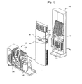
- FIG. 2 is a perspective view showing an air purifying unit constituting the air conditioning system according to the present invention.
- the air purifying unit 200 includes an air ventilating and cleaning unit 210, a total heat exchanger 230 connected to the air ventilating and cleaning unit 210 by means of a duct member 220, and a controller 240 connected to the air ventilating and cleaning unit 210 by wire or wirelessly, for selecting a ventilation mode or a cleaning mode.
- the duct member 220 includes an air supply duct 221 for introducing exterior air and an air discharge duct 222 for discharging interior air. Ends of the air supply duct 221 and the air discharge duct 222 are connected to an air suction opening 211 and an air discharge opening 212, and the other ends thereof are connected to the total heat exchanger 230.
- an air supply connection pipe 224 and an air discharge connection pipe 226 are interposed between the duct member 220 and the total heat exchanger 230 to firmly engage the total heat exchanger 230 and the duct member 220.
- the total heat exchanger 230 heat-exchanges the exterior air introduced into the interior of a room with the interior air discharged to the exterior of the room so that the temperature of the interior of the room cannot rapidly decrease or increase by the exterior air introduced into the interior of the room.
- the total heat exchanger 230 includes an exhausted air suction opening 232 formed on one side of the outer peripheral surface thereof, a supplied air discharge opening 231 separated from the discharged air suction opening 232 by a predetermined distance, an exhausted air discharge opening 234 formed at a position opposite to the exhausted air suction opening 232, a supplied air suction opening 233 formed at a position opposite to the supplied air discharge opening 232, and a total exchanging device (not shown).
- the total heat exchanger 230 further includes an exhausted air fan (not shown) mounted to the interior of a pipe connecting the exhausted air suction opening 232 and the exhausted air discharge opening 234 and an supplied air fan (not shown) mounted to the interior of a pipe connecting the supplied air suction opening 233 and the supplied air discharge opening 231.
- the total heat exchanging device is installed in the interior of the total heat exchanger 230 and heat-exchanges the exterior air and the interior air which are introduced into the total heat exchanger 230 without mixing the exterior air and the interior air.
- the exhausted air suction opening 232 is formed in the same side surface as the supplied air discharge opening 231 and the exhausted air discharge opening 234 is formed in the same side surface as the supplied air suction opening.
- the positions of the exhausted air suction opening 232 and the supplied air discharge opening 231 and the positions of the exhausted air discharge opening 234 and the supplied air suction opening 233 can be varied according to the kind of the total heat exchanger 230.
- the exhausted air suction opening 232 is connected to an exhausted air connecting pipe 212 to flow the interior air discharged from the air ventilating and cleaning unit 210. Further, the supplied air discharge opening 231 is connected to the supplied air connecting pipe 211 to supply the exterior air to the air ventilating and cleaning unit 210.
- a user can control the air ventilating and cleaning unit 210 and/or the total heat exchanger 230 so that they can be operated individually or in connection with each other through an operation button provided in the controller.
- the air ventilating and cleaning unit 210 is driven together with the total heat exchanger 230 to circulate the interior air and the exterior air.
- the cleaning mode is selected, only the air ventilating and cleaning unit 219 is operated to that the interior air can be purified in the interior of the air ventilating and cleaning unit 210 and be discharged into the interior of the room again.
- FIG. 3 is a block diagram showing the constitution of the air conditioning system according to the present invention.
- the air conditioning system includes an air conditioner 100 generating defrosting operation information, an air purifying unit 200 controlling functions for ventilating and purifying interior air on the basis of the defrosting operation information, and a controller 240 transmitting instruction for operation mode selection to the air purifying unit 200.
- the controller 240 is connected to the air purifying unit 200 by wire or wirelessly and transmits a manipulation instruction signal to the air purifying unit 200.
- controller 240 includes an input section 242 for inputting operation and stop instructions of the air purifying unit 200 and an instruction on the operation mode and a display section 244 displaying the operation state of the air purifying unit 200.
- the air purifying unit 200 includes an air ventilating and cleaning unit 210 and a total heat exchanger 230.
- the air ventilating and cleaning unit 210 includes a signal receiving section 216 receiving various signals transmitted form the controller 240 and the air conditioner 100, a measurement section 218 for measuring the interior temperature and the exterior temperature, and a first control section 214 to which an instruction received by the signal receiving section 216 is transmitted.
- the signal receiving section 216 receives defrosting operation information and transfers the information to the first control section 214 in the case in which the defrosting operation of the air conditioner 100 si performed.
- the measurement section 218 measures the interior temperature and the exterior temperature repetitively for a predetermined period of time and transfers the measured temperatures to the first control section 214.
- the first control section 214 applies control instruction to the total heat exchanger 230 on the basis of the defrosting operation information received by the signal receiving section 216.
- the first control section transfers the control instruction to the total heat exchanger 230 according to the interior temperature and the exterior temperature which are measured by the measurement section 218.
- the first control section 214 compares the difference value between the measured interior and exterior temperatures with a set temperature value and generates a control instruction corresponding to the comparison.
- the total heat exchanger 230 includes a second control section 236 receiving the instruction from the first control section 214 and a fan driving section 237 for regulating the wind amount of a fan under the control of the second control section 236.
- the second control section 236 receives the control signal from the first control section 214 to control the fan driving section 237.
- the fan driving section 237 drives an air supplying fan 238 and an air exhausting fan 239 which are mounted to the interior of the total heat exchanger 230.
- the fan driving section 237 controls the drive of the air supplying fan 238 and the air exhausting fan 239 according to the control signal of the second control section 236.
- FIG. 4 is a flow chart showing a control method of the air conditioning system according to the present invention.
- the air purifying unit 200 and the air conditioner 100 are operated in connection with each other.(S300)
- the first control section 214 of the air purifying unit 200 determines whether the air conditioner 100 is in the defrosting operation state.
- the first control section 214 applies the drive control signals of the air supplying fan 238 and the air exhausting fan 239 to the total heat exchanger 230 to control the air ventilating and purifying functions.
- the first control section 214 applies a control instruction to the second control section 232 so that the total heat exchanger 230 can perform a ventilation restricting operation in the case in which the air conditioner 100 performs the defrosting operation.
- the second control section 236 controls the fan driving section 237 so as to perform the ventilation restricting operation.
- the ventilation restraining operation refers to an operation in which the air supplying fan 238 and the air exhausting fan 239 are selectively stopped to prevent the load of the air conditioner 100 from being increased since the load of the air conditioner 100 increases if the total heat exchange is performed in the total heat exchanger 230 in the case in which the exterior temperature is lower than the interior temperature by a set temperature value.
- the second control section 236 continuously receives the defrosting operation information of the air conditioner 100 from the first control section 214 until the defrosting operation of the air conditioner 100 is completed.
- the mode of the air purifying unit 200 is changed from the operation mode to the ventilation mode in the case in which the air conditioner 100 is not in the defrosting operation state.(S315)
- the first control section 214 changes the mode of the air purifying unit 200 to the ventilation mode and controls the air purifying unit 200 so that the wind amount can be regulated to a set wind amount.
- the second control section 236 controls the drive of the air supplying fan 238 and the air exhausting fan 239 according to the instruction applied by the first control section 214.
- the interior and exterior temperatures are measured.
- the first control section 214 applies a control signal for measuring the interior and exterior temperatures to the measurement section 218.
- the measurement section 218 measures the interior temperature and the exterior temperature with at least one temperature sensor and applies the measured values to the first control section 214.
- the first control section 214 determines the ventilation restraining area by comparing the difference between the measured interior and exterior temperatures with a set temperature value.
- the ventilation restraining area refers to a case in which the difference value between the interior and exterior temperatures is above a predetermined temperature value.
- the air purifying unit 200 performs the ventilation restraining operation.(S330)
- the first control section 214 applies a signal to the second control section 236 so that at least one of the air supplying fan 238 and the air exhausting fan 239 is stopped, and accordingly one of the air supplying fan 238 and the air exhausting fan 239 is stopped.
- the interior and exterior temperatures are measured again by the measurement section 218.
- whether the ventilation restraining operation is to be performed again is determined by comparing the interior and exterior temperatures measured by the first control section again with the predetermined temperature again.
- the step returns to the step S330.
- the interior temperature is maintained at an optimal state, thereby improving the comfortableness in the interior of a room.
- an air conditioning system and a control method of the air conditioning system since an air conditioner and an air purifying unit used for ventilation and purification of the interior air are controlled so as to be operated in connection with each other so that the ventilating and purifying functions of the air purifying unit is controlled so as to maintain the interior temperature when the air conditioner performs the defrosting operation, the comfortableness in the interior of a room is improved and the reliability and value of the product is improved. Therefore, the industrial applicability of the present invention is high.
Landscapes
- Engineering & Computer Science (AREA)
- Chemical & Material Sciences (AREA)
- Combustion & Propulsion (AREA)
- Mechanical Engineering (AREA)
- General Engineering & Computer Science (AREA)
- Signal Processing (AREA)
- Physics & Mathematics (AREA)
- Fuzzy Systems (AREA)
- Mathematical Physics (AREA)
- Human Computer Interaction (AREA)
- Fluid Mechanics (AREA)
- Air Conditioning Control Device (AREA)
Claims (10)
- Steuerverfahren für ein Klimaanlagensystem, wobei das Klimaanlagensystem eine Klimaanlage (100), die Abtauvorgangsinformationen erzeugt, und eine Luftreinigungseinheit (200) aufweist, die in Zusammenhang mit der Klimaanlage betrieben wird und Belüftungs-und Reinigungsfunktionen auf Basis der Abtauvorgangsinformationen der Klimaanlage steuert, wobei die Luftreinigungseinheit (200) eine Belüftungs- und Luftreinigungseinheit (210) aufweist, die Innenluft belüftet und reinigt, sowie einen gesamten Wärmetauscher (230), der die Innenluft mit Außenluft tauscht, und wobei die Luftreinigungseinheit (200) des Weiteren einen Abluftventilator (239) zum Ausstoßen der innenluft nach außen und einen Zuluftventilator (238) zum Einführen der Außenluft in das Innere eines Raums aufweist, und wobei der Antrieb des Zuluftventilators und des Abluftventilators gemäß dem Abtauvorgang der Klimaanlage gesteuert wird,
wobei das Verfahren die folgenden Schritte aufweist:Betreiben der Klimaanlage (100) und der Luftreinigungseinheit (200) in Zusammenhang miteinander;Ermitteln, ob die Klimaanlage (100) einen Abtauvorgang durchführt; undSteuern des Betriebs der Luftreinigungseinheit (200) gemäß dem Ermittlungsergebnis,wobei in dem Fall, in dem die Klimaanlage (100) einen Abtauvorgang durchführt, der Antrieb eines Abluftventilators (239) und eines Zuluftventilators (238) gesteuert wird. - Steuerverfahren nach Anspruch 1, wobei in dem Fall, in dem die Klimaanlage (100) den Abtauvorgang durchführt, der Antrieb von mindestens dem Abluftventilator (239) oder dem Zuluftventilator (238) angehalten wird.
- Steuerverfahren nach Anspruch 1, wobei in dem Fall, in dem die Klimaanlage (100) nicht den Abtauvorgang durchführt, die Luftreinigungseinheit (200) in einem festgelegten Belüftungsmodus betrieben wird.
- Steuerverfahren nach Anspruch 3, wobei, nachdem die Luftreinigungseinheit (200) in dem festgelegten Belüftungsmodus über eine erste Bezugszeitspanne betrieben wurde, ein Belüftungsrückhaltebereich festgelegt wird.
- Steuerverfahren nach Anspruch 4, wobei der Belüftungsrückhaltebereich ein Fall ist, bei dem der Differenzwert zwischen den Innen- und Außentemperaturen über einem vorgegebenen Temperaturwert liegt.
- Steuerverfahren nach Anspruch 4, wobei in dem Fall, in dem die Luftreinigungseinheit (200) nicht in dem Belüftungsrückhaltebereich ist, der Zuluftventilator (238) und der Abluftventilator (249) so angetrieben werden, dass sie einer festgelegten Windmenge entsprechen.
- Steuerverfahren nach Anspruch 4, wobei in dem Fall, in dem der Belüftungsrückhaltebereich festgelegt ist, der Antrieb von mindestens dem Abluftventilator (239) oder dem Zuluftventilator (238), welche die Luftreinigungseinheit (200) bilden, angehalten wird.
- Steuerverfahren nach Anspruch 7, wobei, nachdem eine zweite Bezugszeitspanne in dem Zustand verstreicht, in dem der Antrieb von mindestens dem Abluftventilator (239) oder dem Zuluftventilator (238) angehalten wird, der Belüftungsrückhaltebereich erneut festgelegt wird.
- Steuerverfahren nach Anspruch 8, wobei in dem Fall, in dem die Luftreinigungseinheit (200) in dem Belüftungsrückhaltebereich nach der erneuten Festlegung des Belüftungsrückhaltebereichs ist, der angehaltene Zustand des Antriebs des Zuluftventilators (238) oder des Abluftventilators (239) beibehalten wird.
- Steuerverfahren nach Anspruch 9, wobei in dem Fall, in dem die Luftreinigungseinheit (200) nicht in dem Belüftungsrückhaltebereich nach der erneuten Festlegung des Belüftungsrückhaltebereichs ist, der Zuluftventilator (238) und der Abluftventilator (239) so angetrieben werden, dass sie einer festgelegten Windmenge entsprechen.
Applications Claiming Priority (2)
| Application Number | Priority Date | Filing Date | Title |
|---|---|---|---|
| KR1020060016300A KR101186325B1 (ko) | 2006-02-20 | 2006-02-20 | 공기조화 시스템 및 그 제어방법 |
| PCT/KR2006/005245 WO2007097513A2 (en) | 2006-02-20 | 2006-12-06 | Air conditioning system and control method thereof |
Publications (3)
| Publication Number | Publication Date |
|---|---|
| EP1987295A2 EP1987295A2 (de) | 2008-11-05 |
| EP1987295A4 EP1987295A4 (de) | 2012-03-14 |
| EP1987295B1 true EP1987295B1 (de) | 2013-07-03 |
Family
ID=38437790
Family Applications (1)
| Application Number | Title | Priority Date | Filing Date |
|---|---|---|---|
| EP06823952.4A Not-in-force EP1987295B1 (de) | 2006-02-20 | 2006-12-06 | Klimaanlage und steuerverfahren dafür |
Country Status (5)
| Country | Link |
|---|---|
| EP (1) | EP1987295B1 (de) |
| KR (1) | KR101186325B1 (de) |
| CN (1) | CN101631994B (de) |
| ES (1) | ES2422861T3 (de) |
| WO (1) | WO2007097513A2 (de) |
Families Citing this family (13)
| Publication number | Priority date | Publication date | Assignee | Title |
|---|---|---|---|---|
| WO2008150098A2 (en) * | 2007-06-04 | 2008-12-11 | Young Ryong Kim | Air conditioner having fire extinguishing system |
| WO2010032430A1 (ja) * | 2008-09-16 | 2010-03-25 | パナソニック株式会社 | 空気調和装置 |
| CN101571309B (zh) * | 2009-05-11 | 2011-04-20 | 杭州共远科技有限公司 | 空调远程监测与控制系统 |
| KR20100128812A (ko) * | 2009-05-29 | 2010-12-08 | 엘지전자 주식회사 | 환기장치 및 환기장치의 제어방법 |
| CN102192567A (zh) * | 2010-03-05 | 2011-09-21 | 方芳 | 中央空调的节能控制装置 |
| US8663362B2 (en) * | 2011-02-11 | 2014-03-04 | Trane International Inc. | Air cleaning systems and methods |
| US8696800B2 (en) * | 2011-03-30 | 2014-04-15 | Trane International Inc. | Systems and methods for cleaning air |
| US10537089B2 (en) | 2013-02-06 | 2020-01-21 | The Curators Of The University Of Missouri | Waste heat recovery systems and methods for a livestock barn |
| CN106322558B (zh) * | 2016-09-09 | 2019-12-10 | 广东美的暖通设备有限公司 | 多联机空调器系统及其室外机、除霜控制方法及装置 |
| WO2018093547A1 (en) * | 2016-11-16 | 2018-05-24 | The Curators Of The University Of Missouri | Waste heat recovery systems and methods for a livestock barn |
| GB2581163B (en) * | 2019-02-05 | 2021-02-17 | Oairo Alliance Ltd | An air conditioning or climate control system and method |
| KR102532499B1 (ko) * | 2020-06-11 | 2023-05-18 | 주식회사 아모그린텍 | 환기형 공기청정기 및 이의 운전방법 |
| KR20210154284A (ko) * | 2020-06-11 | 2021-12-21 | 주식회사 아모그린텍 | 환기형 공기청정기 및 이의 운전방법 |
Family Cites Families (15)
| Publication number | Priority date | Publication date | Assignee | Title |
|---|---|---|---|---|
| JPS57175416A (en) * | 1981-04-20 | 1982-10-28 | Toyota Motor Corp | Controller for air conditioner |
| JPS58153034A (ja) * | 1982-03-08 | 1983-09-10 | Matsushita Electric Ind Co Ltd | 空気調和装置 |
| DE4142365A1 (de) * | 1990-12-20 | 1992-07-02 | Gold Star Co | Verschmutzungsgrad-messvorrichtung und -verfahren fuer ein luftreinigungsgeraet |
| US5364026A (en) * | 1991-11-14 | 1994-11-15 | Control Resources, Inc. | Ventilation fan control |
| JPH0828930A (ja) * | 1994-07-20 | 1996-02-02 | Fujitsu General Ltd | 空気調和機 |
| CA2134168C (en) * | 1994-10-24 | 2002-06-11 | Frederic Lagace | Ventilation system |
| JP3378724B2 (ja) * | 1996-04-09 | 2003-02-17 | 三洋電機株式会社 | 空気調和機の除霜制御方法 |
| KR100225640B1 (ko) * | 1997-06-27 | 1999-10-15 | 윤종용 | 공기조화기의 제상제어방법 |
| US6289974B1 (en) * | 1997-07-11 | 2001-09-18 | Elastek, Inc. | Integrated heat recovery ventilator HEPA filter using a HEPA filter material regenerative heat exchanger |
| JP3019081B1 (ja) * | 1998-10-07 | 2000-03-13 | ダイキン工業株式会社 | 外気温検出機能を備えた空調室外機 |
| CN1111683C (zh) * | 1998-12-04 | 2003-06-18 | 广东科龙空调器有限公司 | 空调控制系统 |
| JP2001056132A (ja) * | 1999-08-16 | 2001-02-27 | Daikin Ind Ltd | 空気調和装置 |
| FR2860284B1 (fr) * | 2003-09-30 | 2005-11-18 | Lgl France | Procede de regulation de l'alimentation en air neuf d'une installation de distribution d'air conditionne. |
| KR100546618B1 (ko) * | 2004-06-24 | 2006-01-26 | 엘지전자 주식회사 | 공조 시스템 |
| WO2006011704A2 (en) * | 2004-07-27 | 2006-02-02 | Lg Electronics Inc. | Air conditioner |
-
2006
- 2006-02-20 KR KR1020060016300A patent/KR101186325B1/ko not_active Expired - Fee Related
- 2006-12-06 ES ES06823952T patent/ES2422861T3/es active Active
- 2006-12-06 EP EP06823952.4A patent/EP1987295B1/de not_active Not-in-force
- 2006-12-06 CN CN2006800501403A patent/CN101631994B/zh not_active Expired - Fee Related
- 2006-12-06 WO PCT/KR2006/005245 patent/WO2007097513A2/en not_active Ceased
Also Published As
| Publication number | Publication date |
|---|---|
| EP1987295A4 (de) | 2012-03-14 |
| WO2007097513A2 (en) | 2007-08-30 |
| ES2422861T3 (es) | 2013-09-16 |
| WO2007097513A3 (en) | 2009-05-22 |
| KR20070083057A (ko) | 2007-08-23 |
| CN101631994A (zh) | 2010-01-20 |
| KR101186325B1 (ko) | 2012-09-27 |
| CN101631994B (zh) | 2012-09-26 |
| EP1987295A2 (de) | 2008-11-05 |
Similar Documents
| Publication | Publication Date | Title |
|---|---|---|
| US8249751B2 (en) | Power saving air-conditioning system | |
| US7832465B2 (en) | Affordable and easy to install multi-zone HVAC system | |
| EP1987295B1 (de) | Klimaanlage und steuerverfahren dafür | |
| EP2428740B1 (de) | Klimaanlage und Betriebsverfahren dafür | |
| CN101178242A (zh) | 操作空调系统的设备及控制空调系统的方法 | |
| EP3792565B1 (de) | Klimatisierungssystem | |
| KR0148173B1 (ko) | 공기조화기의 건조운전방법 | |
| JP2004150679A (ja) | 空気調和システム | |
| EP1980796B1 (de) | Klimaanlagensystem | |
| US5317907A (en) | Air conditioning apparatus having ambient air-conditioning unit and a plurality of personal air-conditioning units connected to outdoor unit | |
| CN1333212C (zh) | 空调系统 | |
| KR20120083140A (ko) | 공기조화시스템 및 그 제어방법 | |
| KR101573363B1 (ko) | 공기조화기 및 그 제어방법 | |
| JP2003312474A (ja) | 鉄道車両空調装置の除湿制御方法、および鉄道車両空調装置 | |
| EP1598605B1 (de) | Klimaeinheitsystem und Betriebssteuereinrichtung dafür | |
| JP3425295B2 (ja) | 空気調和システム装置 | |
| US20060207273A1 (en) | Method of controlling over-load cooling operation of air conditioner | |
| JP3672548B2 (ja) | 空気調和機の乾燥運転方法 | |
| JP4282499B2 (ja) | 空気調和装置 | |
| KR101785655B1 (ko) | 공기조화시스템 | |
| JP2004333044A (ja) | 空気調和システム | |
| WO2024157395A1 (ja) | 空気調和システム | |
| JP4155765B2 (ja) | 空気調和装置及びその除霜運転解除方法 | |
| JP2002039604A (ja) | 設備制御システム | |
| JP2003207195A (ja) | 空気調和装置 |
Legal Events
| Date | Code | Title | Description |
|---|---|---|---|
| PUAI | Public reference made under article 153(3) epc to a published international application that has entered the european phase |
Free format text: ORIGINAL CODE: 0009012 |
|
| 17P | Request for examination filed |
Effective date: 20080612 |
|
| AK | Designated contracting states |
Kind code of ref document: A2 Designated state(s): AT BE BG CH CY CZ DE DK EE ES FI FR GB GR HU IE IS IT LI LT LU LV MC NL PL PT RO SE SI SK TR |
|
| AX | Request for extension of the european patent |
Extension state: AL BA HR MK RS |
|
| R17D | Deferred search report published (corrected) |
Effective date: 20090522 |
|
| A4 | Supplementary search report drawn up and despatched |
Effective date: 20120210 |
|
| RIC1 | Information provided on ipc code assigned before grant |
Ipc: F24F 11/00 20060101AFI20120206BHEP |
|
| DAX | Request for extension of the european patent (deleted) | ||
| GRAP | Despatch of communication of intention to grant a patent |
Free format text: ORIGINAL CODE: EPIDOSNIGR1 |
|
| GRAS | Grant fee paid |
Free format text: ORIGINAL CODE: EPIDOSNIGR3 |
|
| GRAA | (expected) grant |
Free format text: ORIGINAL CODE: 0009210 |
|
| AK | Designated contracting states |
Kind code of ref document: B1 Designated state(s): AT BE BG CH CY CZ DE DK EE ES FI FR GB GR HU IE IS IT LI LT LU LV MC NL PL PT RO SE SI SK TR |
|
| REG | Reference to a national code |
Ref country code: GB Ref legal event code: FG4D |
|
| REG | Reference to a national code |
Ref country code: CH Ref legal event code: EP Ref country code: AT Ref legal event code: REF Ref document number: 620006 Country of ref document: AT Kind code of ref document: T Effective date: 20130715 |
|
| REG | Reference to a national code |
Ref country code: IE Ref legal event code: FG4D |
|
| REG | Reference to a national code |
Ref country code: DE Ref legal event code: R096 Ref document number: 602006037153 Country of ref document: DE Effective date: 20130829 |
|
| REG | Reference to a national code |
Ref country code: ES Ref legal event code: FG2A Ref document number: 2422861 Country of ref document: ES Kind code of ref document: T3 Effective date: 20130916 |
|
| PG25 | Lapsed in a contracting state [announced via postgrant information from national office to epo] |
Ref country code: SI Free format text: LAPSE BECAUSE OF FAILURE TO SUBMIT A TRANSLATION OF THE DESCRIPTION OR TO PAY THE FEE WITHIN THE PRESCRIBED TIME-LIMIT Effective date: 20130703 |
|
| REG | Reference to a national code |
Ref country code: AT Ref legal event code: MK05 Ref document number: 620006 Country of ref document: AT Kind code of ref document: T Effective date: 20130703 |
|
| REG | Reference to a national code |
Ref country code: NL Ref legal event code: VDEP Effective date: 20130703 |
|
| REG | Reference to a national code |
Ref country code: LT Ref legal event code: MG4D |
|
| PG25 | Lapsed in a contracting state [announced via postgrant information from national office to epo] |
Ref country code: AT Free format text: LAPSE BECAUSE OF FAILURE TO SUBMIT A TRANSLATION OF THE DESCRIPTION OR TO PAY THE FEE WITHIN THE PRESCRIBED TIME-LIMIT Effective date: 20130703 Ref country code: IS Free format text: LAPSE BECAUSE OF FAILURE TO SUBMIT A TRANSLATION OF THE DESCRIPTION OR TO PAY THE FEE WITHIN THE PRESCRIBED TIME-LIMIT Effective date: 20131103 Ref country code: LT Free format text: LAPSE BECAUSE OF FAILURE TO SUBMIT A TRANSLATION OF THE DESCRIPTION OR TO PAY THE FEE WITHIN THE PRESCRIBED TIME-LIMIT Effective date: 20130703 Ref country code: PT Free format text: LAPSE BECAUSE OF FAILURE TO SUBMIT A TRANSLATION OF THE DESCRIPTION OR TO PAY THE FEE WITHIN THE PRESCRIBED TIME-LIMIT Effective date: 20131104 Ref country code: CY Free format text: LAPSE BECAUSE OF FAILURE TO SUBMIT A TRANSLATION OF THE DESCRIPTION OR TO PAY THE FEE WITHIN THE PRESCRIBED TIME-LIMIT Effective date: 20130619 Ref country code: BE Free format text: LAPSE BECAUSE OF FAILURE TO SUBMIT A TRANSLATION OF THE DESCRIPTION OR TO PAY THE FEE WITHIN THE PRESCRIBED TIME-LIMIT Effective date: 20130703 Ref country code: SE Free format text: LAPSE BECAUSE OF FAILURE TO SUBMIT A TRANSLATION OF THE DESCRIPTION OR TO PAY THE FEE WITHIN THE PRESCRIBED TIME-LIMIT Effective date: 20130703 |
|
| PG25 | Lapsed in a contracting state [announced via postgrant information from national office to epo] |
Ref country code: LV Free format text: LAPSE BECAUSE OF FAILURE TO SUBMIT A TRANSLATION OF THE DESCRIPTION OR TO PAY THE FEE WITHIN THE PRESCRIBED TIME-LIMIT Effective date: 20130703 Ref country code: FI Free format text: LAPSE BECAUSE OF FAILURE TO SUBMIT A TRANSLATION OF THE DESCRIPTION OR TO PAY THE FEE WITHIN THE PRESCRIBED TIME-LIMIT Effective date: 20130703 Ref country code: PL Free format text: LAPSE BECAUSE OF FAILURE TO SUBMIT A TRANSLATION OF THE DESCRIPTION OR TO PAY THE FEE WITHIN THE PRESCRIBED TIME-LIMIT Effective date: 20130703 Ref country code: GR Free format text: LAPSE BECAUSE OF FAILURE TO SUBMIT A TRANSLATION OF THE DESCRIPTION OR TO PAY THE FEE WITHIN THE PRESCRIBED TIME-LIMIT Effective date: 20131004 Ref country code: NL Free format text: LAPSE BECAUSE OF FAILURE TO SUBMIT A TRANSLATION OF THE DESCRIPTION OR TO PAY THE FEE WITHIN THE PRESCRIBED TIME-LIMIT Effective date: 20130703 |
|
| PG25 | Lapsed in a contracting state [announced via postgrant information from national office to epo] |
Ref country code: CY Free format text: LAPSE BECAUSE OF FAILURE TO SUBMIT A TRANSLATION OF THE DESCRIPTION OR TO PAY THE FEE WITHIN THE PRESCRIBED TIME-LIMIT Effective date: 20130703 |
|
| PG25 | Lapsed in a contracting state [announced via postgrant information from national office to epo] |
Ref country code: DK Free format text: LAPSE BECAUSE OF FAILURE TO SUBMIT A TRANSLATION OF THE DESCRIPTION OR TO PAY THE FEE WITHIN THE PRESCRIBED TIME-LIMIT Effective date: 20130703 Ref country code: EE Free format text: LAPSE BECAUSE OF FAILURE TO SUBMIT A TRANSLATION OF THE DESCRIPTION OR TO PAY THE FEE WITHIN THE PRESCRIBED TIME-LIMIT Effective date: 20130703 Ref country code: RO Free format text: LAPSE BECAUSE OF FAILURE TO SUBMIT A TRANSLATION OF THE DESCRIPTION OR TO PAY THE FEE WITHIN THE PRESCRIBED TIME-LIMIT Effective date: 20130703 Ref country code: SK Free format text: LAPSE BECAUSE OF FAILURE TO SUBMIT A TRANSLATION OF THE DESCRIPTION OR TO PAY THE FEE WITHIN THE PRESCRIBED TIME-LIMIT Effective date: 20130703 Ref country code: CZ Free format text: LAPSE BECAUSE OF FAILURE TO SUBMIT A TRANSLATION OF THE DESCRIPTION OR TO PAY THE FEE WITHIN THE PRESCRIBED TIME-LIMIT Effective date: 20130703 |
|
| PLBE | No opposition filed within time limit |
Free format text: ORIGINAL CODE: 0009261 |
|
| STAA | Information on the status of an ep patent application or granted ep patent |
Free format text: STATUS: NO OPPOSITION FILED WITHIN TIME LIMIT |
|
| 26N | No opposition filed |
Effective date: 20140404 |
|
| REG | Reference to a national code |
Ref country code: DE Ref legal event code: R119 Ref document number: 602006037153 Country of ref document: DE |
|
| REG | Reference to a national code |
Ref country code: DE Ref legal event code: R097 Ref document number: 602006037153 Country of ref document: DE Effective date: 20140404 |
|
| REG | Reference to a national code |
Ref country code: CH Ref legal event code: PL |
|
| GBPC | Gb: european patent ceased through non-payment of renewal fee |
Effective date: 20131206 |
|
| PG25 | Lapsed in a contracting state [announced via postgrant information from national office to epo] |
Ref country code: LU Free format text: LAPSE BECAUSE OF FAILURE TO SUBMIT A TRANSLATION OF THE DESCRIPTION OR TO PAY THE FEE WITHIN THE PRESCRIBED TIME-LIMIT Effective date: 20131206 Ref country code: MC Free format text: LAPSE BECAUSE OF FAILURE TO SUBMIT A TRANSLATION OF THE DESCRIPTION OR TO PAY THE FEE WITHIN THE PRESCRIBED TIME-LIMIT Effective date: 20130703 |
|
| REG | Reference to a national code |
Ref country code: IE Ref legal event code: MM4A |
|
| REG | Reference to a national code |
Ref country code: FR Ref legal event code: ST Effective date: 20140829 |
|
| REG | Reference to a national code |
Ref country code: DE Ref legal event code: R119 Ref document number: 602006037153 Country of ref document: DE Effective date: 20140701 |
|
| PG25 | Lapsed in a contracting state [announced via postgrant information from national office to epo] |
Ref country code: LI Free format text: LAPSE BECAUSE OF NON-PAYMENT OF DUE FEES Effective date: 20131231 Ref country code: IE Free format text: LAPSE BECAUSE OF NON-PAYMENT OF DUE FEES Effective date: 20131206 Ref country code: CH Free format text: LAPSE BECAUSE OF NON-PAYMENT OF DUE FEES Effective date: 20131231 Ref country code: DE Free format text: LAPSE BECAUSE OF NON-PAYMENT OF DUE FEES Effective date: 20140701 |
|
| PG25 | Lapsed in a contracting state [announced via postgrant information from national office to epo] |
Ref country code: GB Free format text: LAPSE BECAUSE OF NON-PAYMENT OF DUE FEES Effective date: 20131206 Ref country code: FR Free format text: LAPSE BECAUSE OF NON-PAYMENT OF DUE FEES Effective date: 20131231 |
|
| PG25 | Lapsed in a contracting state [announced via postgrant information from national office to epo] |
Ref country code: TR Free format text: LAPSE BECAUSE OF FAILURE TO SUBMIT A TRANSLATION OF THE DESCRIPTION OR TO PAY THE FEE WITHIN THE PRESCRIBED TIME-LIMIT Effective date: 20130703 |
|
| PG25 | Lapsed in a contracting state [announced via postgrant information from national office to epo] |
Ref country code: BG Free format text: LAPSE BECAUSE OF FAILURE TO SUBMIT A TRANSLATION OF THE DESCRIPTION OR TO PAY THE FEE WITHIN THE PRESCRIBED TIME-LIMIT Effective date: 20130703 Ref country code: HU Free format text: LAPSE BECAUSE OF FAILURE TO SUBMIT A TRANSLATION OF THE DESCRIPTION OR TO PAY THE FEE WITHIN THE PRESCRIBED TIME-LIMIT; INVALID AB INITIO Effective date: 20061206 |
|
| PGFP | Annual fee paid to national office [announced via postgrant information from national office to epo] |
Ref country code: ES Payment date: 20161118 Year of fee payment: 11 Ref country code: IT Payment date: 20161215 Year of fee payment: 11 |
|
| PG25 | Lapsed in a contracting state [announced via postgrant information from national office to epo] |
Ref country code: IT Free format text: LAPSE BECAUSE OF NON-PAYMENT OF DUE FEES Effective date: 20171206 |
|
| REG | Reference to a national code |
Ref country code: ES Ref legal event code: FD2A Effective date: 20190702 |
|
| PG25 | Lapsed in a contracting state [announced via postgrant information from national office to epo] |
Ref country code: ES Free format text: LAPSE BECAUSE OF NON-PAYMENT OF DUE FEES Effective date: 20171207 |