EP1987409B1 - Dispositif d'entrée universelle destine a un changeur de bobine d'inductance - Google Patents
Dispositif d'entrée universelle destine a un changeur de bobine d'inductance Download PDFInfo
- Publication number
- EP1987409B1 EP1987409B1 EP07733902.6A EP07733902A EP1987409B1 EP 1987409 B1 EP1987409 B1 EP 1987409B1 EP 07733902 A EP07733902 A EP 07733902A EP 1987409 B1 EP1987409 B1 EP 1987409B1
- Authority
- EP
- European Patent Office
- Prior art keywords
- voltage
- signal
- input signal
- converting system
- converting
- Prior art date
- Legal status (The legal status is an assumption and is not a legal conclusion. Google has not performed a legal analysis and makes no representation as to the accuracy of the status listed.)
- Not-in-force
Links
- 238000012545 processing Methods 0.000 claims description 5
- 230000001012 protector Effects 0.000 claims 2
- 238000012544 monitoring process Methods 0.000 description 7
- 238000010586 diagram Methods 0.000 description 5
- 238000000034 method Methods 0.000 description 5
- 230000008859 change Effects 0.000 description 3
- 230000009471 action Effects 0.000 description 2
- 238000013459 approach Methods 0.000 description 2
- 230000008901 benefit Effects 0.000 description 2
- 230000008030 elimination Effects 0.000 description 2
- 238000003379 elimination reaction Methods 0.000 description 2
- 230000001427 coherent effect Effects 0.000 description 1
- 238000013461 design Methods 0.000 description 1
- 238000005516 engineering process Methods 0.000 description 1
- 238000004519 manufacturing process Methods 0.000 description 1
- 230000008569 process Effects 0.000 description 1
- 230000009467 reduction Effects 0.000 description 1
Images


Classifications
-
- H—ELECTRICITY
- H02—GENERATION; CONVERSION OR DISTRIBUTION OF ELECTRIC POWER
- H02P—CONTROL OR REGULATION OF ELECTRIC MOTORS, ELECTRIC GENERATORS OR DYNAMO-ELECTRIC CONVERTERS; CONTROLLING TRANSFORMERS, REACTORS OR CHOKE COILS
- H02P13/00—Arrangements for controlling transformers, reactors or choke coils, for the purpose of obtaining a desired output
- H02P13/06—Arrangements for controlling transformers, reactors or choke coils, for the purpose of obtaining a desired output by tap-changing; by rearranging interconnections of windings
-
- G—PHYSICS
- G05—CONTROLLING; REGULATING
- G05F—SYSTEMS FOR REGULATING ELECTRIC OR MAGNETIC VARIABLES
- G05F1/00—Automatic systems in which deviations of an electric quantity from one or more predetermined values are detected at the output of the system and fed back to a device within the system to restore the detected quantity to its predetermined value or values, i.e. retroactive systems
- G05F1/10—Regulating voltage or current
- G05F1/12—Regulating voltage or current wherein the variable actually regulated by the final control device is AC
- G05F1/14—Regulating voltage or current wherein the variable actually regulated by the final control device is AC using tap transformers or tap changing inductors as final control devices
- G05F1/147—Regulating voltage or current wherein the variable actually regulated by the final control device is AC using tap transformers or tap changing inductors as final control devices with motor driven tap switch
- G05F1/153—Regulating voltage or current wherein the variable actually regulated by the final control device is AC using tap transformers or tap changing inductors as final control devices with motor driven tap switch controlled by discharge tubes or semiconductor devices
Definitions
- the invention relates to a signal converting system for a tap changer, more specifically, the invention relates to an electronic signal converting device capable of receiving a variety of differing signal levels with the same equipment.
- Tap-changers used, for example, to change the tap settings on a commercial transformer, utilize input signals for control and monitoring.
- Known tap-changers utilize electromechanical contacts for control.
- a user typically connects their equipment (e.g. transformer) to the tap-changer motor drive.
- Digital signals are an effective means to control and monitor the functioning of the tap-changer.
- a "1" and a "0” describe a status of full voltage (On) or zero voltage (Off).
- these two statuses are typically described by, for example: AC of 50-60 Hz, 110-240V ⁇ 15% of rated voltage, or DC of 24-48V ⁇ 10% of rated voltage.
- AC 50-60 Hz
- DC of 24-48V ⁇ 10% of rated voltage In the traditional motor drive, this is a user choice, where the motor drive must be equipped with a special apparatus to interface with a particular voltage for switching of the electromechanical contacts. Accordingly, a different apparatus is required to be used for different voltage levels.
- a digital input (DI) is constructed to function for relatively low voltage levels and consumes several mA of current (at the relatively low voltage levels), it will correspondingly dissipate a relatively large amount of energy for higher voltages.
- the DI must be isolated and protected for over-voltage.
- the system may be required to consume a relatively large amount of current for a relatively short period of time, This is especially so for a DI that is energy economical.
- the higher current contributes to the burning of oxides on the digital output (DO) in the case that it is a relay.
- the signals must be converted to a suitable digital signal with relatively high resolution.
- the system may accept AC or DC voltages in a range from about 10V-390V.
- the power to the electronics is derived from the input signal itself (a self-powered solution). Accordingly, because the system can accept many differing voltage levels, the former apparatus variations are reduced to a single solution.
- this universal input system allows the manufacturer to tool up for production of only one type of unit, and the user does not have to store various system and system parts proprietary to particular voltage levels.
- Objects of the invention are further achieved by the elimination of electromechanical contacts, which have been replaced by use of electronics.
- the reduction and/or elimination in the number electromechanical contacts, which are subject to mechanical failure, provides for a system with increased reliability.
- Electronics further allow for greatly improved monitoring and diagnostics, in particular, over a network connection from a remote location.
- programming and settings may also be remotely executed via the electronic system.
- the input channel utilizes electronics with the voltage variations being handled within the software of a microprocessor.
- the level to distinguish a logical "0" or a logical "1" being set and controlled within the software.
- data means any indicia, signals, marks, symbols, domains, symbol sets, representations, and any other physical form or forms representing information, whether permanent or temporary, whether visible, audible, acoustic, electric, magnetic, electromagnetic or otherwise manifested.
- data as used to represent predetermined information in one physical form shall be deemed to encompass any and all representations of the same predetermined information in a different physical form or forms.
- network includes both networks and internetworks of all kinds, including the Internet, and is not limited to any particular network or inter-network.
- Coupled means a relationship between or among two or more devices, apparatus, files, programs, media, components, networks, systems, subsystems, and/or means, constituting any one or more of (a) a connection, whether direct or through one or more other devices, apparatus, files, programs, media, components, networks, systems, subsystems, or means, (b) a communications relationship, whether direct or through one or more other devices, apparatus, files, programs, media, components, networks, systems, subsystems, or means, and/or (c) a functional relationship in which the operation of any one or more devices, apparatus, files, programs, media, components, networks, systems, subsystems, or means depends, in whole or in part, on the operation of any one or more others thereof.
- a signal converting system for a tap changer comprising, an input signal for driving a tap changer motor drive and an electronic voltage converting device for receiving the input signal and for outputting a digital signal corresponding to the input signal.
- the system is provided such that the output digital signal controls the tap changer motor drive, then can move the connected tap changer to a tap selection based on the input signal or other common control tasks such as operation inhibit of the motor drive, external emergency stop of the motor drive or go to nth position (tap selection).
- the system is further provided such that the electronic voltage converting device is capable of receiving differing input signal voltages from about 10V to about 390V, such that a single electronic voltage converting device may be used with different input signal voltage levels.
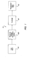
- FIG. 1 generally depicts system 10, which includes user input signal 20, electronic voltage converting device 100, controller 30 and tap-changer motor drive 40.
- User input signal 20 may comprise virtually any common commercial input signal ranging from about 10V to about 390V ⁇ 10-15% AC or DC and AC from 50-60 Hz. This is highly desirable because system 10 provides a device that includes an essentially universal input, being capable of reception of all common commercial signal levels. This allows the user to become familiar with and stock parts for only a single system, which can be used for each of the user's differing switching applications.
- User input signal 20 is coupled to electronic voltage converting device 100, which is provided to receive and convert the signal before outputting a signal to controller 30.
- Electronic voltage converting device 100 is provided having universal input capability, being able to receive and convert user input signal 20 within the range of from about 10V to about 390V ⁇ 10-15% AC or DC and AC from 50-60 Hz as stated above.
- Electronic voltage converting device 100 will be discussed in greater detail in connection with FIGS. 2 and 3 .
- Controller 30 is coupled to electronic voltage converting device 100 and receives a converted output signal that corresponds to user input signal 20. Controller 30 then "decodes” or interprets the received signal to actuate tap-changer motor drive 40 to, for example, change a tap-setting on a transformer, It is contemplated that controller 30 may comprise but is not limited to, a central processing unit (CPU), a field programmable gate array (FPGA), and combinations thereof.
- CPU central processing unit
- FPGA field programmable gate array
- Tap-changer motor drive 40 may comprise any typical motor drive unit as is commonly used in industry for accomplishing, for example, a tap change, or other common control tasks such as, operation inhibit of the motor drive, external emergency stop of the motor drive or go to nth position (tap selection).
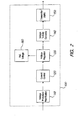
- electronic voltage converting device 100 comprises voltage protection / rectification 110, current control 120, voltage regulator 130, voltage to duty converter 140 and transmitter 150.
- Voltage protection / rectification 110 provides for over-voltage protection as well as rectification of the received user input signal 20. It is contemplated that the over-voltage protection may comprise, for example, a varistor 112 provided to shunt any excess voltage to ground to prevent damage to the equipment in the event of an over-voltage condition.
- Varistor 112 is coupled to voltage rectifier 114 ( FIG. 3 ), which may comprise virtually any commercially available rectifier for converting user input signal 20. It should be noted that, while the received signal is rectified at this stage, it is not filtered.
- Voltage protection / rectification 110 is coupled to current control 120.
- Current control 120 is provided to protect system 10 from an over current condition. For example, because user input signal 20 may vary from about 10V to about 390V ⁇ 10-15% AC or DC and AC from 50-60 Hz, the higher the voltage level of user input signal 20, the higher the associated current will be. To counteract this process, current control 120 monitors the current load such that, when the measured current reaches about 0.4 mA, a current load is created or developed by current control 120 for a few microseconds to maintain control of the overall circuit current.
- Current control 120 is further coupled to voltage regulator 130.
- the signal voltage is manipulated and altered as needed.
- system 10 may be described as a self-powered system because power for running the electronics is derived from the received signal. This is highly desirable as is may not always be convenient to have to supply power to tap-changing equipment located in a user's switch yard.
- voltage regulator 130 receives the signal and generates a reference voltage 160 that may further be used by system 10. It is contemplated that voltage regulator 130 may comprise, in one advantageous embodiment, a serial regulator.
- Voltage regulator 130 is coupled to voltage to duty converter 140.
- the received signal may further be converted to a relatively low frequency signal, for example but not limited to around 1.5 KHz.
- the signal may further have a varying duty cycle from about 50% to about 99%, and typically at least 8-bit resolution. It should be noted that the DC current is relatively low, typically in a range of approximately 40 ⁇ A.
- Voltage to duty converter 140 may, in one advantageous embodiment, be coupled to transmitter 150. Once the received signal has been appropriately modified by electronic voltage converting device 100, the signal may be output by transmitter 150 to controller 30 for decoding and processing.
- transmitter 150 may comprise, for example, an opto-couple device, which advantageously has relatively low current consumption.
- the output signal may further comprise a pulse-width modulated (PWM) signal, corresponding to user input signal 20.
- PWM pulse-width modulated
- transmitter 150 may comprise, for example, an opto-couple device, which advantageously has relatively low current consumption.
- the output signal may further comprise a pulse-width modulated (PWM) signal, corresponding to user input signal 20.
- PWM pulse-width modulated
- system 10 is fully electronic, substantially eliminating the electromechanical contacts commonly utilized in existing systems, thereby reducing chances of system failure due to wear and tear electromechanical contacts are known for.
- system 10 is fully electronic, this provides for ease of monitoring of system 10 over, for example, a network connection (not shown).
- FIG. 4 a flow diagram of the advantageous embodiment discussed in connection with FIGS. 1-3 is illustrated.
- the system 10 receives an input signal 202, which corresponds to a desired actuation for the tap-changer.
- System 10 monitors the received signal to determine whether the received signal exceeds a threshold voltage level 204. If the received signal exceeds a threshold level, the over voltage protection will dissipate the excess voltage 204 to prevent damage to the system.
- the over voltage protection may comprise a varistor that will shunt excess voltage away from the system. It is contemplated that the over voltage protection may include an inverse time delay characteristics such that upon a sharp increase in voltage, the over voltage protection with shunt excess voltage away from the system relatively quickly.
- the remaining signal is then rectified 208.
- the system determines whether the received signal current exceeds a threshold value 210. If so, the system will generate a current load to limit the signal current 212. As stated in connection with FIGS. 1-3 , this threshold value may be approximately 0.4 mA. If the current does not exceed the threshold value or the system has limited the current via the current load, the system then provides voltage regulation for the signal 214. In this manner, a reference voltage may be generated for use by the system such that an external or separate power source for powering the electronics is unnecessary.
- the system may then convert a frequency of the received signal to a desired frequency 216.
- the frequency is converted to approximately 1.5 KHz.
- the system may transmit the altered signal 218 to a controller.
- the system may then translate or decode the signal 220 to determine the correct action to take with the tap-changer equipment. Once this is determined, the tap-changer is actuated 222 to accomplish the desired action.
- System 10 then provides a fully integrated single solution for accurately handling all of the common voltage variations commonly encountered within a switchyard for a tap-changer. Additionally, system 10 effectively eliminates use of electromechanical contacts for control of the tap-changer, thereby increasing overall system reliability. Finally, system 10 provides a highly a flexible approach to monitoring and diagnostics of a tap-changer, even from a remote location.
Landscapes
- Engineering & Computer Science (AREA)
- Power Engineering (AREA)
- Automation & Control Theory (AREA)
- Electromagnetism (AREA)
- General Physics & Mathematics (AREA)
- Radar, Positioning & Navigation (AREA)
- Physics & Mathematics (AREA)
- Rectifiers (AREA)
- Control Of Electrical Variables (AREA)
- Control Of Electric Motors In General (AREA)
- Power Conversion In General (AREA)
- Selective Calling Equipment (AREA)
- Remote Monitoring And Control Of Power-Distribution Networks (AREA)
Claims (10)
- Système convertisseur de signaux pour un changeur de prise, comprenant :un dispositif convertisseur de tension électronique (100) destiné à recevoir un signal d'entrée (20) servant à entraîner un entraînement de moteur de changeur de prise, et destiné à sortir un signal numérique correspondant audit signal d'entrée, ledit dispositif convertisseur de tension électronique comportant :un protecteur en tension et un redresseur de tension (110) destinés à assurer une protection contre les surtensions et un redressement de tension ;une unité de commande de courant (120) destinée à fournir une charge de courant en cas d'augmentation du niveau de tension dudit signal d'entrée ;un régulateur de tension (130) pour fournir une tension de référence ;caractérisé par un convertisseur tension/rapport cyclique (140) destiné à convertir une fréquence et un rapport cyclique dudit signal d'entrée, etun émetteur (150) couplé au convertisseur tension/rapport cyclique ; etune unité de commande (30) comprenant une unité de traitement destinée à décoder et à traiter un signal numérique sorti par l'émetteur à destination de l'unité de commande ;ledit signal numérique de sortie commandant l'entraînement de moteur de changeur de prise en fonction dudit signal d'entrée ;ledit dispositif convertisseur de tension électronique étant adapté à recevoir des tensions différentes du signal d'entrée allant d'environ 10 V à environ 390 V de façon à permettre l'utilisation d'un seul dispositif convertisseur de tension électronique avec des niveaux de tension différents du signal d'entrée.
- Système convertisseur de signaux selon la revendication 1, dans lequel ledit dispositif convertisseur de tension électronique est apte à convertir des signaux d'entrée aussi bien en courant alternatif qu'en courant continu.
- Système convertisseur de signaux selon la revendication 1, dans lequel ledit protecteur en tension comprend une varistance.
- Système convertisseur de signaux selon la revendication 1, dans lequel la charge de courant est créée à un courant dans un intervalle allant d'environ 0,1 mA à environ 2 mA.
- Système convertisseur de signaux selon la revendication 1, dans lequel ledit régulateur de tension comprend un régulateur série.
- Système convertisseur de signaux selon la revendication 1, dans lequel ledit signal d'entrée est converti en une fréquence dans l'intervalle allant d'environ 0,5 kHz à environ 5 kHz.
- Système convertisseur de signaux selon la revendication 1, dans lequel ledit émetteur est un émetteur optoélectronique.
- Système convertisseur de signaux selon la revendication 7, dans lequel ledit émetteur optoélectronique fait appel à une modulation de largeur d'impulsion.
- Système convertisseur de signaux selon la revendication 1, dans lequel ledit dispositif de traitement est choisi dans le groupe constitué par : une unité centrale de traitement (CPU), un réseau prédiffusé programmable par l'utilisateur (FPGA) et des combinaisons de ceux-ci.
- Système convertisseur de signaux selon la revendication 1, dans lequel ledit signal d'entrée comprend une tâche de commande choisie dans le groupe constitué par : une interdiction de fonctionnement de l'entraînement de moteur, un arrêt d'urgence externe de l'entraînement de moteur et des combinaisons de ceux-ci.
Applications Claiming Priority (2)
| Application Number | Priority Date | Filing Date | Title |
|---|---|---|---|
| US11/358,198 US7432697B2 (en) | 2006-02-21 | 2006-02-21 | Universal input device for a tap changer |
| PCT/IB2007/000425 WO2007096750A2 (fr) | 2006-02-21 | 2007-02-21 | Dispositif d'entrée universelle destine a un changeur de bobine d'inductance |
Publications (2)
| Publication Number | Publication Date |
|---|---|
| EP1987409A2 EP1987409A2 (fr) | 2008-11-05 |
| EP1987409B1 true EP1987409B1 (fr) | 2016-09-14 |
Family
ID=38325203
Family Applications (1)
| Application Number | Title | Priority Date | Filing Date |
|---|---|---|---|
| EP07733902.6A Not-in-force EP1987409B1 (fr) | 2006-02-21 | 2007-02-21 | Dispositif d'entrée universelle destine a un changeur de bobine d'inductance |
Country Status (9)
| Country | Link |
|---|---|
| US (1) | US7432697B2 (fr) |
| EP (1) | EP1987409B1 (fr) |
| JP (1) | JP2009528010A (fr) |
| KR (1) | KR101365278B1 (fr) |
| CN (1) | CN101416134B (fr) |
| BR (1) | BRPI0708088A2 (fr) |
| RU (1) | RU2442208C2 (fr) |
| UA (1) | UA97637C2 (fr) |
| WO (1) | WO2007096750A2 (fr) |
Families Citing this family (4)
| Publication number | Priority date | Publication date | Assignee | Title |
|---|---|---|---|---|
| CN102830385A (zh) * | 2012-09-27 | 2012-12-19 | 秦皇岛开发区海纳电测仪器有限责任公司 | 电流互感器的切换装置及其控制方法 |
| KR101505472B1 (ko) | 2013-10-25 | 2015-03-30 | 고려대학교 산학협력단 | 변압기용 이중 불감대 탭 절환기 및 제어방법 |
| CN106292457A (zh) * | 2016-09-29 | 2017-01-04 | 中国核动力研究设计院 | 一种应用于反应性仪的程控高压电源装置 |
| US10862298B2 (en) * | 2018-04-11 | 2020-12-08 | Schweitzer Engineering Laboratories, Inc. | Duty cycle modulated universal binary input circuit with reinforced isolation |
Family Cites Families (14)
| Publication number | Priority date | Publication date | Assignee | Title |
|---|---|---|---|---|
| US4843339A (en) | 1987-10-28 | 1989-06-27 | Burr-Brown Corporation | Isolation amplifier including precision voltage-to-duty-cycle converter and low ripple, high bandwidth charge balance demodulator |
| US5581173A (en) | 1991-01-03 | 1996-12-03 | Beckwith Electric Co., Inc. | Microcontroller-based tap changer controller employing half-wave digitization of A.C. signals |
| DE4214431C3 (de) | 1992-04-30 | 1996-08-14 | Reinhausen Maschf Scheubeck | Stufenschalter mit Motorantrieb |
| JP2996377B2 (ja) | 1993-07-10 | 1999-12-27 | 永田 勝彦 | 交流入力電圧に応じて単巻変圧器の降圧比を制御する装置 |
| US5642290A (en) * | 1993-09-13 | 1997-06-24 | Siemens Energy & Automation, Inc. | Expansion chassis for a voltage regulator controller |
| US5619121A (en) | 1995-06-29 | 1997-04-08 | Siemens Energy & Automation, Inc. | Load voltage based tap changer monitoring system |
| BR9904367A (pt) * | 1998-09-29 | 2001-03-20 | Siemens Power Transm & Distrib | Sistema eletrônico de indicação de posição de derivação |
| JP4593724B2 (ja) * | 2000-03-27 | 2010-12-08 | 東京エレクトロン株式会社 | 電力制御装置、電力制御方法及び熱処理装置 |
| CA2410854A1 (fr) * | 2000-06-01 | 2001-12-06 | Powertec International | Systeme et procedes de gestion d'energie et de courant cote ligne |
| RU2197059C2 (ru) * | 2000-06-16 | 2003-01-20 | Федеральное государственное унитарное предприятие "Научно-производственный центр "Полюс" | Блок периодической развертки для преобразователя напряжения с широтно-импульсной модуляцией |
| JP2004079144A (ja) * | 2002-08-22 | 2004-03-11 | Mitsumi Electric Co Ltd | 光ディスク装置 |
| US20050068013A1 (en) * | 2003-09-30 | 2005-03-31 | Scoggins Robert L. | Apparatus and methods for power regulation of electrical loads to provide reduction in power consumption with reversing contactors |
| US7417411B2 (en) * | 2005-09-14 | 2008-08-26 | Advanced Power Technologies, Llc | Apparatus and method for monitoring tap positions of load tap changer |
| US7323852B2 (en) * | 2005-09-14 | 2008-01-29 | Hoffman Gary R | Sensing load tap changer (LTC) conditions |
-
2006
- 2006-02-21 US US11/358,198 patent/US7432697B2/en not_active Expired - Fee Related
-
2007
- 2007-02-21 UA UAA200811367A patent/UA97637C2/uk unknown
- 2007-02-21 JP JP2008555894A patent/JP2009528010A/ja active Pending
- 2007-02-21 EP EP07733902.6A patent/EP1987409B1/fr not_active Not-in-force
- 2007-02-21 WO PCT/IB2007/000425 patent/WO2007096750A2/fr not_active Ceased
- 2007-02-21 CN CN2007800061253A patent/CN101416134B/zh not_active Expired - Fee Related
- 2007-02-21 RU RU2008137584/08A patent/RU2442208C2/ru not_active IP Right Cessation
- 2007-02-21 KR KR1020087020333A patent/KR101365278B1/ko not_active Expired - Fee Related
- 2007-02-21 BR BRPI0708088-3A patent/BRPI0708088A2/pt not_active Application Discontinuation
Also Published As
| Publication number | Publication date |
|---|---|
| CN101416134A (zh) | 2009-04-22 |
| BRPI0708088A2 (pt) | 2011-05-17 |
| EP1987409A2 (fr) | 2008-11-05 |
| KR20080110582A (ko) | 2008-12-18 |
| WO2007096750A2 (fr) | 2007-08-30 |
| CN101416134B (zh) | 2013-04-24 |
| WO2007096750A3 (fr) | 2007-11-01 |
| UA97637C2 (uk) | 2012-03-12 |
| RU2442208C2 (ru) | 2012-02-10 |
| RU2008137584A (ru) | 2010-03-27 |
| US7432697B2 (en) | 2008-10-07 |
| JP2009528010A (ja) | 2009-07-30 |
| US20070194764A1 (en) | 2007-08-23 |
| KR101365278B1 (ko) | 2014-02-19 |
Similar Documents
| Publication | Publication Date | Title |
|---|---|---|
| US5671115A (en) | Circuit arrangement for driving a contactor | |
| EP2725435B1 (fr) | Commande d'une fonction de sécurité d'une machine électrique | |
| EP1231705A3 (fr) | Convertisseur de puissance avec des circuits pour la commande améliorée de l'opération de redresseurs synchrones dans celui-ci | |
| EP3018794B1 (fr) | Unité d'alimentation électrique pour dispositif électronique intelligent autoalimenté | |
| EP1987409B1 (fr) | Dispositif d'entrée universelle destine a un changeur de bobine d'inductance | |
| US20190036451A1 (en) | Voltage regulator including a buck converter pass switch | |
| JP2009528010A5 (fr) | ||
| CN108599595A (zh) | 一种开关电源及其副边到原边的通信方法 | |
| RU2475931C2 (ru) | Управляемый привод | |
| EP1974247B1 (fr) | Détection de l'état opérationnel d'un système | |
| EP4113226B1 (fr) | Circuit à limitation de puissance pour modules d' e/s. | |
| US11996250B2 (en) | Switch assembly with drive system, and method for safely operating a switch assembly | |
| US20240195303A1 (en) | Buck-boost converter for contactor drive | |
| US20090296426A1 (en) | Switch mode power supply | |
| EP4601169A1 (fr) | Circuit d'alimentation pour rendre une puissance d'alimentation commandée | |
| EP2858257B1 (fr) | Appareil de transmission de signal isolé | |
| CN101501799B (zh) | 在电力系统设备的控制单元中生成数据信号的信号生成单元和方法 | |
| KR100779494B1 (ko) | 배터리의 역전압 차단장치 | |
| KR200412051Y1 (ko) | 전원공급장치 | |
| CN103780062B (zh) | 电气机器的安全功能控制 | |
| JP2005094890A (ja) | スイッチング電源回路 | |
| TW200708916A (en) | Control circuit for proportional driving switching power supply | |
| JP2014092851A (ja) | スイッチング電源装置 |
Legal Events
| Date | Code | Title | Description |
|---|---|---|---|
| PUAI | Public reference made under article 153(3) epc to a published international application that has entered the european phase |
Free format text: ORIGINAL CODE: 0009012 |
|
| 17P | Request for examination filed |
Effective date: 20080806 |
|
| AK | Designated contracting states |
Kind code of ref document: A2 Designated state(s): AT BE BG CH CY CZ DE DK EE ES FI FR GB GR HU IE IS IT LI LT LU LV MC NL PL PT RO SE SI SK TR |
|
| DAX | Request for extension of the european patent (deleted) | ||
| 17Q | First examination report despatched |
Effective date: 20120802 |
|
| GRAP | Despatch of communication of intention to grant a patent |
Free format text: ORIGINAL CODE: EPIDOSNIGR1 |
|
| INTG | Intention to grant announced |
Effective date: 20160512 |
|
| GRAS | Grant fee paid |
Free format text: ORIGINAL CODE: EPIDOSNIGR3 |
|
| GRAA | (expected) grant |
Free format text: ORIGINAL CODE: 0009210 |
|
| AK | Designated contracting states |
Kind code of ref document: B1 Designated state(s): AT BE BG CH CY CZ DE DK EE ES FI FR GB GR HU IE IS IT LI LT LU LV MC NL PL PT RO SE SI SK TR |
|
| REG | Reference to a national code |
Ref country code: GB Ref legal event code: FG4D |
|
| REG | Reference to a national code |
Ref country code: CH Ref legal event code: EP |
|
| REG | Reference to a national code |
Ref country code: IE Ref legal event code: FG4D |
|
| REG | Reference to a national code |
Ref country code: AT Ref legal event code: REF Ref document number: 829662 Country of ref document: AT Kind code of ref document: T Effective date: 20161015 |
|
| REG | Reference to a national code |
Ref country code: DE Ref legal event code: R096 Ref document number: 602007047921 Country of ref document: DE |
|
| RAP2 | Party data changed (patent owner data changed or rights of a patent transferred) |
Owner name: ABB SCHWEIZ AG |
|
| REG | Reference to a national code |
Ref country code: LT Ref legal event code: MG4D |
|
| REG | Reference to a national code |
Ref country code: NL Ref legal event code: MP Effective date: 20160914 |
|
| PG25 | Lapsed in a contracting state [announced via postgrant information from national office to epo] |
Ref country code: LT Free format text: LAPSE BECAUSE OF FAILURE TO SUBMIT A TRANSLATION OF THE DESCRIPTION OR TO PAY THE FEE WITHIN THE PRESCRIBED TIME-LIMIT Effective date: 20160914 Ref country code: FI Free format text: LAPSE BECAUSE OF FAILURE TO SUBMIT A TRANSLATION OF THE DESCRIPTION OR TO PAY THE FEE WITHIN THE PRESCRIBED TIME-LIMIT Effective date: 20160914 |
|
| REG | Reference to a national code |
Ref country code: AT Ref legal event code: MK05 Ref document number: 829662 Country of ref document: AT Kind code of ref document: T Effective date: 20160914 |
|
| PG25 | Lapsed in a contracting state [announced via postgrant information from national office to epo] |
Ref country code: SE Free format text: LAPSE BECAUSE OF FAILURE TO SUBMIT A TRANSLATION OF THE DESCRIPTION OR TO PAY THE FEE WITHIN THE PRESCRIBED TIME-LIMIT Effective date: 20160914 Ref country code: NL Free format text: LAPSE BECAUSE OF FAILURE TO SUBMIT A TRANSLATION OF THE DESCRIPTION OR TO PAY THE FEE WITHIN THE PRESCRIBED TIME-LIMIT Effective date: 20160914 Ref country code: LV Free format text: LAPSE BECAUSE OF FAILURE TO SUBMIT A TRANSLATION OF THE DESCRIPTION OR TO PAY THE FEE WITHIN THE PRESCRIBED TIME-LIMIT Effective date: 20160914 Ref country code: GR Free format text: LAPSE BECAUSE OF FAILURE TO SUBMIT A TRANSLATION OF THE DESCRIPTION OR TO PAY THE FEE WITHIN THE PRESCRIBED TIME-LIMIT Effective date: 20161215 Ref country code: ES Free format text: LAPSE BECAUSE OF FAILURE TO SUBMIT A TRANSLATION OF THE DESCRIPTION OR TO PAY THE FEE WITHIN THE PRESCRIBED TIME-LIMIT Effective date: 20160914 |
|
| PG25 | Lapsed in a contracting state [announced via postgrant information from national office to epo] |
Ref country code: RO Free format text: LAPSE BECAUSE OF FAILURE TO SUBMIT A TRANSLATION OF THE DESCRIPTION OR TO PAY THE FEE WITHIN THE PRESCRIBED TIME-LIMIT Effective date: 20160914 Ref country code: EE Free format text: LAPSE BECAUSE OF FAILURE TO SUBMIT A TRANSLATION OF THE DESCRIPTION OR TO PAY THE FEE WITHIN THE PRESCRIBED TIME-LIMIT Effective date: 20160914 |
|
| REG | Reference to a national code |
Ref country code: DE Ref legal event code: R081 Ref document number: 602007047921 Country of ref document: DE Owner name: ABB SCHWEIZ AG, CH Free format text: FORMER OWNER: ABB TECHNOLOGY LTD, ZUERICH, CH |
|
| PG25 | Lapsed in a contracting state [announced via postgrant information from national office to epo] |
Ref country code: CZ Free format text: LAPSE BECAUSE OF FAILURE TO SUBMIT A TRANSLATION OF THE DESCRIPTION OR TO PAY THE FEE WITHIN THE PRESCRIBED TIME-LIMIT Effective date: 20160914 Ref country code: PT Free format text: LAPSE BECAUSE OF FAILURE TO SUBMIT A TRANSLATION OF THE DESCRIPTION OR TO PAY THE FEE WITHIN THE PRESCRIBED TIME-LIMIT Effective date: 20170116 Ref country code: IS Free format text: LAPSE BECAUSE OF FAILURE TO SUBMIT A TRANSLATION OF THE DESCRIPTION OR TO PAY THE FEE WITHIN THE PRESCRIBED TIME-LIMIT Effective date: 20170114 Ref country code: PL Free format text: LAPSE BECAUSE OF FAILURE TO SUBMIT A TRANSLATION OF THE DESCRIPTION OR TO PAY THE FEE WITHIN THE PRESCRIBED TIME-LIMIT Effective date: 20160914 Ref country code: AT Free format text: LAPSE BECAUSE OF FAILURE TO SUBMIT A TRANSLATION OF THE DESCRIPTION OR TO PAY THE FEE WITHIN THE PRESCRIBED TIME-LIMIT Effective date: 20160914 Ref country code: SK Free format text: LAPSE BECAUSE OF FAILURE TO SUBMIT A TRANSLATION OF THE DESCRIPTION OR TO PAY THE FEE WITHIN THE PRESCRIBED TIME-LIMIT Effective date: 20160914 Ref country code: BE Free format text: LAPSE BECAUSE OF FAILURE TO SUBMIT A TRANSLATION OF THE DESCRIPTION OR TO PAY THE FEE WITHIN THE PRESCRIBED TIME-LIMIT Effective date: 20160914 |
|
| REG | Reference to a national code |
Ref country code: DE Ref legal event code: R097 Ref document number: 602007047921 Country of ref document: DE |
|
| PLBE | No opposition filed within time limit |
Free format text: ORIGINAL CODE: 0009261 |
|
| STAA | Information on the status of an ep patent application or granted ep patent |
Free format text: STATUS: NO OPPOSITION FILED WITHIN TIME LIMIT |
|
| PG25 | Lapsed in a contracting state [announced via postgrant information from national office to epo] |
Ref country code: DK Free format text: LAPSE BECAUSE OF FAILURE TO SUBMIT A TRANSLATION OF THE DESCRIPTION OR TO PAY THE FEE WITHIN THE PRESCRIBED TIME-LIMIT Effective date: 20160914 |
|
| 26N | No opposition filed |
Effective date: 20170615 |
|
| PG25 | Lapsed in a contracting state [announced via postgrant information from national office to epo] |
Ref country code: MC Free format text: LAPSE BECAUSE OF FAILURE TO SUBMIT A TRANSLATION OF THE DESCRIPTION OR TO PAY THE FEE WITHIN THE PRESCRIBED TIME-LIMIT Effective date: 20160914 |
|
| REG | Reference to a national code |
Ref country code: CH Ref legal event code: PL |
|
| GBPC | Gb: european patent ceased through non-payment of renewal fee |
Effective date: 20170221 |
|
| PG25 | Lapsed in a contracting state [announced via postgrant information from national office to epo] |
Ref country code: CH Free format text: LAPSE BECAUSE OF NON-PAYMENT OF DUE FEES Effective date: 20170228 Ref country code: LI Free format text: LAPSE BECAUSE OF NON-PAYMENT OF DUE FEES Effective date: 20170228 |
|
| REG | Reference to a national code |
Ref country code: IE Ref legal event code: MM4A |
|
| PG25 | Lapsed in a contracting state [announced via postgrant information from national office to epo] |
Ref country code: SI Free format text: LAPSE BECAUSE OF FAILURE TO SUBMIT A TRANSLATION OF THE DESCRIPTION OR TO PAY THE FEE WITHIN THE PRESCRIBED TIME-LIMIT Effective date: 20160914 |
|
| REG | Reference to a national code |
Ref country code: FR Ref legal event code: ST Effective date: 20171031 |
|
| PG25 | Lapsed in a contracting state [announced via postgrant information from national office to epo] |
Ref country code: LU Free format text: LAPSE BECAUSE OF NON-PAYMENT OF DUE FEES Effective date: 20170221 |
|
| PG25 | Lapsed in a contracting state [announced via postgrant information from national office to epo] |
Ref country code: FR Free format text: LAPSE BECAUSE OF NON-PAYMENT OF DUE FEES Effective date: 20170228 |
|
| PG25 | Lapsed in a contracting state [announced via postgrant information from national office to epo] |
Ref country code: IE Free format text: LAPSE BECAUSE OF NON-PAYMENT OF DUE FEES Effective date: 20170221 Ref country code: GB Free format text: LAPSE BECAUSE OF NON-PAYMENT OF DUE FEES Effective date: 20170221 |
|
| PGFP | Annual fee paid to national office [announced via postgrant information from national office to epo] |
Ref country code: DE Payment date: 20180219 Year of fee payment: 12 |
|
| PGFP | Annual fee paid to national office [announced via postgrant information from national office to epo] |
Ref country code: TR Payment date: 20180221 Year of fee payment: 12 Ref country code: BG Payment date: 20180220 Year of fee payment: 12 Ref country code: IT Payment date: 20180227 Year of fee payment: 12 |
|
| PG25 | Lapsed in a contracting state [announced via postgrant information from national office to epo] |
Ref country code: HU Free format text: LAPSE BECAUSE OF FAILURE TO SUBMIT A TRANSLATION OF THE DESCRIPTION OR TO PAY THE FEE WITHIN THE PRESCRIBED TIME-LIMIT; INVALID AB INITIO Effective date: 20070221 |
|
| REG | Reference to a national code |
Ref country code: DE Ref legal event code: R119 Ref document number: 602007047921 Country of ref document: DE |
|
| PG25 | Lapsed in a contracting state [announced via postgrant information from national office to epo] |
Ref country code: CY Free format text: LAPSE BECAUSE OF NON-PAYMENT OF DUE FEES Effective date: 20160914 |
|
| PG25 | Lapsed in a contracting state [announced via postgrant information from national office to epo] |
Ref country code: BG Free format text: LAPSE BECAUSE OF NON-PAYMENT OF DUE FEES Effective date: 20190831 |
|
| PG25 | Lapsed in a contracting state [announced via postgrant information from national office to epo] |
Ref country code: DE Free format text: LAPSE BECAUSE OF NON-PAYMENT OF DUE FEES Effective date: 20190903 |
|
| PG25 | Lapsed in a contracting state [announced via postgrant information from national office to epo] |
Ref country code: IT Free format text: LAPSE BECAUSE OF NON-PAYMENT OF DUE FEES Effective date: 20190221 |
|
| PG25 | Lapsed in a contracting state [announced via postgrant information from national office to epo] |
Ref country code: TR Free format text: LAPSE BECAUSE OF NON-PAYMENT OF DUE FEES Effective date: 20190221 |