EP1987459B1 - System und verfahren zum bewerten und reduzieren der luftverschmutzung durch regelung der luftströmungsventilation - Google Patents
System und verfahren zum bewerten und reduzieren der luftverschmutzung durch regelung der luftströmungsventilation Download PDFInfo
- Publication number
- EP1987459B1 EP1987459B1 EP07706147.1A EP07706147A EP1987459B1 EP 1987459 B1 EP1987459 B1 EP 1987459B1 EP 07706147 A EP07706147 A EP 07706147A EP 1987459 B1 EP1987459 B1 EP 1987459B1
- Authority
- EP
- European Patent Office
- Prior art keywords
- air pollution
- levels
- ventilation
- monitoring station
- urban area
- Prior art date
- Legal status (The legal status is an assumption and is not a legal conclusion. Google has not performed a legal analysis and makes no representation as to the accuracy of the status listed.)
- Active
Links
Images


Classifications
-
- G—PHYSICS
- G06—COMPUTING OR CALCULATING; COUNTING
- G06Q—INFORMATION AND COMMUNICATION TECHNOLOGY [ICT] SPECIALLY ADAPTED FOR ADMINISTRATIVE, COMMERCIAL, FINANCIAL, MANAGERIAL OR SUPERVISORY PURPOSES; SYSTEMS OR METHODS SPECIALLY ADAPTED FOR ADMINISTRATIVE, COMMERCIAL, FINANCIAL, MANAGERIAL OR SUPERVISORY PURPOSES, NOT OTHERWISE PROVIDED FOR
- G06Q50/00—Information and communication technology [ICT] specially adapted for implementation of business processes of specific business sectors, e.g. utilities or tourism
-
- B—PERFORMING OPERATIONS; TRANSPORTING
- B60—VEHICLES IN GENERAL
- B60H—ARRANGEMENTS OF HEATING, COOLING, VENTILATING OR OTHER AIR-TREATING DEVICES SPECIALLY ADAPTED FOR PASSENGER OR GOODS SPACES OF VEHICLES
- B60H1/00—Heating, cooling or ventilating devices
- B60H1/00642—Control systems or circuits; Control members or indication devices for heating, cooling or ventilating devices
- B60H1/00735—Control systems or circuits characterised by their input, i.e. by the detection, measurement or calculation of particular conditions, e.g. signal treatment, dynamic models
- B60H1/00764—Control systems or circuits characterised by their input, i.e. by the detection, measurement or calculation of particular conditions, e.g. signal treatment, dynamic models the input being a vehicle driving condition, e.g. speed
- B60H1/00771—Control systems or circuits characterised by their input, i.e. by the detection, measurement or calculation of particular conditions, e.g. signal treatment, dynamic models the input being a vehicle driving condition, e.g. speed the input being a vehicle position or surrounding, e.g. GPS-based position or tunnel
-
- B—PERFORMING OPERATIONS; TRANSPORTING
- B60—VEHICLES IN GENERAL
- B60H—ARRANGEMENTS OF HEATING, COOLING, VENTILATING OR OTHER AIR-TREATING DEVICES SPECIALLY ADAPTED FOR PASSENGER OR GOODS SPACES OF VEHICLES
- B60H1/00—Heating, cooling or ventilating devices
- B60H1/00642—Control systems or circuits; Control members or indication devices for heating, cooling or ventilating devices
- B60H1/00735—Control systems or circuits characterised by their input, i.e. by the detection, measurement or calculation of particular conditions, e.g. signal treatment, dynamic models
- B60H1/008—Control systems or circuits characterised by their input, i.e. by the detection, measurement or calculation of particular conditions, e.g. signal treatment, dynamic models the input being air quality
-
- B—PERFORMING OPERATIONS; TRANSPORTING
- B60—VEHICLES IN GENERAL
- B60H—ARRANGEMENTS OF HEATING, COOLING, VENTILATING OR OTHER AIR-TREATING DEVICES SPECIALLY ADAPTED FOR PASSENGER OR GOODS SPACES OF VEHICLES
- B60H3/00—Other air-treating devices
- B60H3/0085—Smell or pollution preventing arrangements
-
- F—MECHANICAL ENGINEERING; LIGHTING; HEATING; WEAPONS; BLASTING
- F24—HEATING; RANGES; VENTILATING
- F24F—AIR-CONDITIONING; AIR-HUMIDIFICATION; VENTILATION; USE OF AIR CURRENTS FOR SCREENING
- F24F11/00—Control or safety arrangements
- F24F11/30—Control or safety arrangements for purposes related to the operation of the system, e.g. for safety or monitoring
-
- F—MECHANICAL ENGINEERING; LIGHTING; HEATING; WEAPONS; BLASTING
- F24—HEATING; RANGES; VENTILATING
- F24F—AIR-CONDITIONING; AIR-HUMIDIFICATION; VENTILATION; USE OF AIR CURRENTS FOR SCREENING
- F24F11/00—Control or safety arrangements
- F24F11/62—Control or safety arrangements characterised by the type of control or by internal processing, e.g. using fuzzy logic, adaptive control or estimation of values
- F24F11/63—Electronic processing
- F24F11/65—Electronic processing for selecting an operating mode
-
- F—MECHANICAL ENGINEERING; LIGHTING; HEATING; WEAPONS; BLASTING
- F24—HEATING; RANGES; VENTILATING
- F24F—AIR-CONDITIONING; AIR-HUMIDIFICATION; VENTILATION; USE OF AIR CURRENTS FOR SCREENING
- F24F11/00—Control or safety arrangements
- F24F11/70—Control systems characterised by their outputs; Constructional details thereof
- F24F11/72—Control systems characterised by their outputs; Constructional details thereof for controlling the supply of treated air, e.g. its pressure
- F24F11/74—Control systems characterised by their outputs; Constructional details thereof for controlling the supply of treated air, e.g. its pressure for controlling air flow rate or air velocity
-
- F—MECHANICAL ENGINEERING; LIGHTING; HEATING; WEAPONS; BLASTING
- F24—HEATING; RANGES; VENTILATING
- F24F—AIR-CONDITIONING; AIR-HUMIDIFICATION; VENTILATION; USE OF AIR CURRENTS FOR SCREENING
- F24F8/00—Treatment, e.g. purification, of air supplied to human living or working spaces otherwise than by heating, cooling, humidifying or drying
- F24F8/95—Treatment, e.g. purification, of air supplied to human living or working spaces otherwise than by heating, cooling, humidifying or drying specially adapted for specific purposes
- F24F8/99—Treatment, e.g. purification, of air supplied to human living or working spaces otherwise than by heating, cooling, humidifying or drying specially adapted for specific purposes for treating air sourced from urban areas, e.g. from streets
-
- G—PHYSICS
- G06—COMPUTING OR CALCULATING; COUNTING
- G06Q—INFORMATION AND COMMUNICATION TECHNOLOGY [ICT] SPECIALLY ADAPTED FOR ADMINISTRATIVE, COMMERCIAL, FINANCIAL, MANAGERIAL OR SUPERVISORY PURPOSES; SYSTEMS OR METHODS SPECIALLY ADAPTED FOR ADMINISTRATIVE, COMMERCIAL, FINANCIAL, MANAGERIAL OR SUPERVISORY PURPOSES, NOT OTHERWISE PROVIDED FOR
- G06Q10/00—Administration; Management
- G06Q10/04—Forecasting or optimisation specially adapted for administrative or management purposes, e.g. linear programming or "cutting stock problem"
-
- F—MECHANICAL ENGINEERING; LIGHTING; HEATING; WEAPONS; BLASTING
- F24—HEATING; RANGES; VENTILATING
- F24F—AIR-CONDITIONING; AIR-HUMIDIFICATION; VENTILATION; USE OF AIR CURRENTS FOR SCREENING
- F24F2110/00—Control inputs relating to air properties
- F24F2110/50—Air quality properties
-
- F—MECHANICAL ENGINEERING; LIGHTING; HEATING; WEAPONS; BLASTING
- F24—HEATING; RANGES; VENTILATING
- F24F—AIR-CONDITIONING; AIR-HUMIDIFICATION; VENTILATION; USE OF AIR CURRENTS FOR SCREENING
- F24F2110/00—Control inputs relating to air properties
- F24F2110/50—Air quality properties
- F24F2110/52—Air quality properties of the outside air
-
- Y—GENERAL TAGGING OF NEW TECHNOLOGICAL DEVELOPMENTS; GENERAL TAGGING OF CROSS-SECTIONAL TECHNOLOGIES SPANNING OVER SEVERAL SECTIONS OF THE IPC; TECHNICAL SUBJECTS COVERED BY FORMER USPC CROSS-REFERENCE ART COLLECTIONS [XRACs] AND DIGESTS
- Y02—TECHNOLOGIES OR APPLICATIONS FOR MITIGATION OR ADAPTATION AGAINST CLIMATE CHANGE
- Y02B—CLIMATE CHANGE MITIGATION TECHNOLOGIES RELATED TO BUILDINGS, e.g. HOUSING, HOUSE APPLIANCES OR RELATED END-USER APPLICATIONS
- Y02B30/00—Energy efficient heating, ventilation or air conditioning [HVAC]
- Y02B30/70—Efficient control or regulation technologies, e.g. for control of refrigerant flow, motor or heating
-
- Y—GENERAL TAGGING OF NEW TECHNOLOGICAL DEVELOPMENTS; GENERAL TAGGING OF CROSS-SECTIONAL TECHNOLOGIES SPANNING OVER SEVERAL SECTIONS OF THE IPC; TECHNICAL SUBJECTS COVERED BY FORMER USPC CROSS-REFERENCE ART COLLECTIONS [XRACs] AND DIGESTS
- Y02—TECHNOLOGIES OR APPLICATIONS FOR MITIGATION OR ADAPTATION AGAINST CLIMATE CHANGE
- Y02P—CLIMATE CHANGE MITIGATION TECHNOLOGIES IN THE PRODUCTION OR PROCESSING OF GOODS
- Y02P90/00—Enabling technologies with a potential contribution to greenhouse gas [GHG] emissions mitigation
- Y02P90/80—Management or planning
- Y02P90/84—Greenhouse gas [GHG] management systems
Definitions
- the present invention relates in general to the field of monitoring the air pollution in a given environment, more precisely it relates to systems and methods for estimating local air pollution tendencies and for optimizing in a routine manner the conditions of airflow ventilation of buildings according to air pollution measurements.
- the problem of indoor air pollution is no less severe than the pollution outdoors because outdoor pollution diffuses into the space of buildings, and because inside buildings there are many sources of air pollution emitting pollution into the limited volume of the buildings themselves.
- the present invention is non specific in dealing with air pollutants, and it is suitable for dealing with ultra-fine particles and very small gaseous pollutants which are the most common, the most dangerous and the most cancerous pollutants.
- JP 2004 028387 A describes a remote management and control system for air conditioners.
- Air conditioners are able to send location information and outdoor/indoor environmental information (e.g. air pollution) to a management server which performs centralized management of the plurality of air conditioners.
- the invention has therefore the object to improve current airflow ventilation methods and systems of non-monitored enclosed environments (220).
- the method is comprised of continuously gathering air pollution data and identifying daily frequent air pollution fluctuations in a routine manner in real time from at least one location in the urban area and transmitting the data to at least one computing center.
- the method also includes the steps of performing a preliminary stage of identifying synchronizations regarding tendencies of air pollution levels between different locations of the urban area, and analyzing the data in the computing center and estimating levels of air pollution in at least one location of that same urban area which does not include a monitoring station, based on the preliminary stage.
- the preliminary stage further includes the steps of gathering air pollution tendencies from a second location in the urban area and analyzing patterns, regularities and dependencies regarding differences in air pollution tendencies at the locations of the same urban area by the computing center.
- the method optionally sends the information to an automatic ventilation regulating unit in the enclosed environment, such as a building or a vehicle or to a person located in the urban area.
- the method may also include gathering from at least one location in the urban area data concerning intervening factors.
- the intervening factors include parameters which influence the concentration, diffusion and dispersion of air pollution and transmitting the data of the intervening factors to the computing center.
- the air pollution tendencies in sections of the urban area which do not include a monitoring station are estimated in accordance with data from remote monitoring stations and the intervening factors.
- the intervening factors optionally include the distance between each monitoring station and each location, wind direction, wind speed, temperature, topography, barometric pressure, humidity levels, angles or vectors of these parameters in relation to each location, and the composition of air and sunlight intensity.
- the method optionally also includes the step of calculating a factor for determining the relative influence of each monitoring station in estimating air pollution tendencies of each location which does not include a monitoring station when monitoring air pollution levels in at least two different locations of the same urban area.
- the factor for each possible pair of a monitoring station and a location is calculated according to the intervening factors.
- the analyzed data is transmitted to recipients in the urban area.
- the analyzed data relates to real time relative air pollution levels in the surroundings of the recipient.
- the analyzed data includes commands concerning the ventilation of the enclosed environment with air from the outside.
- the commands are determined according to current estimations of relative levels of air pollution in the surroundings of the enclosed environment compared to a calculated threshold of relative air pollution level for each location of the enclosed environment.
- the calculations rely on predictions of air pollution levels according to prediction algorithms, such as learning algorithms.
- the threshold is determined by the computing center according to relative levels of pollution in previous ventilation points in time.
- the method measures the time span between every two consecutive ventilations of the enclosed environment and takes into account the time span in calculating the threshold wherein the longer the time span the higher the threshold.
- the maximum time span between every two consecutive ventilation commands is predefined within each automatic ventilation regulating unit or by the computing center according to relevant parameters of each enclosed environment.
- the method also measures air components in the enclosed environment and takes into account this data in the calculation of the threshold wherein a better composition of air components in the enclosed environment allows a lower threshold.
- the location of the enclosed environment is optionally identified in real time. The locating process is conducted using a global positioning system (GPS) or location identification of cellular device.
- GPS global positioning system
- the ventilation commands are determined in accordance with characteristics of the enclosed environment.
- the characteristics of the enclosed environment optionally include the volume, population and levels of activity inside the enclosed environment.
- the method optionally also includes the step of receiving feedback information from the enclosed environments and adjusting the calculations accordingly.
- the automatic ventilation regulating unit optionally includes a CO2 sensor and the activation of air flow ventilation from the outside is activated when CO2 levels exceed a predefined threshold.
- the system comprises stationary or mobile air pollution monitoring stations placed in the urban area for continuously monitoring routine fluctuations in the air pollution levels at its location.
- the system also includes a second monitoring station operating for a preliminary identification of synchronizations regarding tendencies of air pollution levels between different locations of the same urban area and a centralized optimization and control computing center for gathering and analyzing data of air pollution received from the monitoring stations.
- This information is collected by the computing center through a first communication network and control commands are sent through a second communication network to recipients in the enclosed environments.
- the control commands include ventilation mode data.
- Recipients may be located in sections of the urban area which do not include a monitoring station.
- the recipient may be an automatic ventilation regulation unit or a person located within the urban area.
- a positioning system such as a GPS unit; a cellular communication unit, may be used for determining the location of the recipient.
- the system includes an algorithm for periodic measurements and assessments for predicting regular points in time in which air pollution levels are relatively low.
- the automatic ventilation regulating unit controls the ventilation of the enclosed environment with air from the outside.
- the automatic ventilation regulating unit optionally also includes a timer for activating air flow ventilation from the outside after a predefined time.
- the automatic ventilation regulating unit optionally further includes a CO2 sensor which allows the activation of air flow ventilation from the outside when CO2 levels exceed a predefined threshold.
- the second monitoring station gathers information concerning intervening factors.
- the intervening factors include parameters which influence the concentration, diffusion and dispersion of air pollution.
- the present invention is a system and method for monitoring the levels of air pollution in urban areas for the purpose of transmitting air pollution data and for the purpose of optimizing the conditions of airflow ventilation of buildings according to the data.
- air flow ventilation herein refers to air flow ventilation from the outside into the building, while inside air is excluded; the term airflow circulation refers to indoor air ventilation.
- the disclosed system and method supplies data in real time regarding local air pollution levels or relative levels, i.e. current air pollution levels in relation to previous ones.
- the disclosed system and method makes use of the fluctuations in air pollution levels in order to achieve optimal reduction of air pollution levels inside buildings on a daily basis.
- An embodiment is an example or implementation of the inventions.
- the various appearances of "one embodiment,” “an embodiment” or “some embodiments” do not necessarily all refer to the same embodiments.
- various features of the invention may be described in the context of a single embodiment, the features may also be provided separately or in any suitable combination. Conversely, although the invention may be described herein in the context of separate embodiments for clarity, the invention may also be implemented in a single embodiment.
- Methods of the present invention may be implemented by performing or completing manually, automatically, or a combination thereof, selected steps or tasks.
- the term "method” refers to manners, means, techniques and procedures for accomplishing a given task including, but not limited to, those manners, means, techniques and procedures either known to, or readily developed from known manners, means, techniques and procedures by practitioners of the art to which the invention belongs.
- the descriptions, examples, methods and materials presented in the claims and the specification are not to be construed as limiting but rather as illustrative only.
- bottom”, “below”, “top” and “above” as used herein do not necessarily indicate that a “bottom” component is below a “top” component, or that a component that is “below” is indeed “below” another component or that a component that is “above” is indeed “above” another component.
- directions, components or both may be flipped, rotated, moved in space, placed in a diagonal orientation or position, placed horizontally or vertically, or similarly modified.
- the terms “bottom”, “below”, “top” and “above” may be used herein for exemplary purposes only, to illustrate the relative positioning or placement of certain components, to indicate a first and a second component or to do both.
- One of the main purposes of this system and method is to define optimal times for ventilation in order to achieve a significant and persisting improvement of indoor air quality, in a routine manner, by using nondeterministic, continuous and effective fluctuations in air pollution levels at the surroundings of each building. Achieving this purpose does not require the system to hold absolute air pollution levels at the surroundings of each building, since the decisive factor in defining optimal times for ventilation is the tendency of the fluctuations in relative air pollution levels and not the absolute levels in and of themselves.
- the above mentioned functions of the disclosed system and method require evaluation in real time of relative air pollution levels and their tendencies in the surroundings of each building.
- the suggested system and method can estimate actual or relative air pollution levels in different locations using only one or few monitoring stations in an entire urban area, this monitoring station may provide data regarding actual levels of pollution or merely relative levels of pollution.
- monitoring stations in order to estimate the relative air pollution levels in different locations of the city, monitoring stations do not have to be located in those specific locations.
- the suggested system and method can define optimal times for ventilation in different locations of an entire urban area using only one processing center.
- the suggested system and method is based on air pollution data analysis and characterization of urban air pollution. These, developments present a unique approach, with important ecological advantages, enabling the system to deal effectively with a variety of pollutants and even with small gaseous pollutants and ultra-fine particles which could not be filtered by current state of the art technologies (designed to improve indoor air quality). Fine particles, ultra-fine particles and gaseous pollutants are the most common and most hazardous pollutants. Nevertheless the suggested solution can work with other products designed to improve indoor air quality, such as filters and purifiers, and it can also improve their efficiency and durability. Using this technology, clients could improve their health at the cost of only few dollars per month.
- Embodiments of the present invention offer an efficient solution which significantly reduces the costs of evaluating in real time local air pollution tendencies or levels, the costs of communication channels and required transmissions and the costs of regulation units of airflow ventilation control.
- embodiments of the present invention can provide affordable airflow ventilation control devices for any building type, ranging from small rooms to large complexes of buildings.
- the use of the term building refers to any kind of structure, apartment, office etc.
- Empirical data gathered from selected cities throughout the world demonstrate and establish that dramatic fluctuations, an increase and decrease of air pollution levels - recur in each day.
- the results show that everyday in most cities there are times when air pollution levels drop to a value which is tenth of the highest levels of that day, in average. In some cities the average difference between the most polluted and the cleanest points in time is up to 30 times greater.
- Figure 8 is a diagram illustrating an average of daily maximal values compared to an average of daily minimal values of air pollution levels in six different urban areas.
- the sampling covered the entire year (otherwise, sampled by intervals of 22 days) skipping weekends and holidays because industrial activity and traffic are relatively low in these days.
- the sampling covered approximately a continuous month and a half.
- the data covered an entire year.
- Figure 8 demonstrates the recurrence of dramatic fluctuations each day in six different urban areas. The fact that all cities show a similar pattern, despite the differences in sampling, strengthens the claim that significant fluctuations of air pollution levels recur over the day.
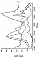
- Figure 9 is a diagram illustrating the recurrence of significant fluctuations of air pollution levels as it was monitored in the city of London over a period of seventeen sampled days covering an entire year (sampled by intervals of 22 days).
- Figure 10 is a diagram illustrating an entire year of measured fluctuations in the city of Haifa. As shown, air pollution fluctuations recur the entire year. Additionally, numerous fluctuations, especially in the winter, exceed maximum levels presented in figure io. Air pollution levels are characterized by unpredictable, continuous, frequent and significant fluctuations that occur each day.
- Figure li is a diagram illustrating such nondeterministic fluctuations. This diagram shows air pollution fluctuations as they were measured on four different days in the city of London. As illustrated by the data in the graph of Figure 11 , the levels of air pollution do not show any regularity.
- Air pollution fluctuations do not take place according to predetermined cycles. Therefore there is no way to predict accurately the value of air pollution level in sequential points in time, in specific locations.
- systems such as neural networks, designed to predict air pollution levels
- these methods cannot deal efficiently with changes, they are not sensitive enough to detect local irregularities, they are not accurate and they are not adapted for analyzing air pollution in high resolution. For instance, these systems are not able to identify differences of air pollution tendencies and levels over minutes and dozens of minutes.
- these systems could serve the suggested system and method in the future, but for now there is no way to predict precisely what will be the change of pollution levels in minutes, tens of minutes, or in any singular point in time months from now.
- Air pollution fluctuations in order to schedule the ventilation of buildings to the optimal times raises two main problems: First, there are feasibility and application problems. For example, air pollution fluctuations are not cyclic or predetermined. Therefore a system and a method is needed for deciding whether to ventilate in a certain point in time or to wait to the following point in time in order to achieve an optimal air quality in buildings.
- the second problem is the high cost of such systems for each building.
- Only professional monitoring stations are sensitive enough to detect brief changes of air pollution levels effectively, in real - time and in high resolution.
- the cost of professional monitoring stations is thousands of dollars per unit to say the least, and a constant, professional operation of the monitoring stations is needed for each building. Locating large, expensive and professional monitoring station at the surroundings of each building is not practical. Additionally, a connection must be established between monitoring stations and computers which must work according to programs capable of estimating the cleanest appropriate points in time for ventilation.
- Air pollution fluctuations are not cyclic or predetermined and different parts of the urban city may show different levels of air pollution.
- urban areas tend to include vast homogeneous environments in terms of their air pollution tendencies. It is likely that in many cases an entire urban area will be a single environment in terms of air pollution tendencies.
- a resemblance in air pollution tendencies is a resemblance in the times in which air pollution levels increase or decrease, and in the times of minimum and maximum values.
- the fluctuations in the monitored levels in the different locations tend to coincide.
- Figure i is a diagram illustrating the monitored levels of air pollution as they were monitored in four different sections in the city of Tel Aviv over a period of six days. As it is apparent from this diagram, although different levels of pollution were measured in the four monitoring stations the measured tendencies were primarily the same in all areas and the minimum levels, such as points 130, 140 and 150, and maximum levels, such as points 100, 110 and 120, coincided. While some sections may not be synchronized with one another, it is likely that two different sections of the same urban area may show detectible pattern or regularity regarding their differences in air pollution tendencies. Research conducted by the inventors has shown that these findings are characteristic of fluctuations in air pollution levels in urban areas.
- the disclosed system and method proposes to make use of this phenomenon. Additionally, the disclosed system and method is designed to identify patterns and regularities regarding differences in air pollution tendencies between different parts of the urban area and make use of this phenomenon.
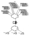
- FIG. 2 is a schematic illustration of the principal system components located in an urban area according to embodiments of the present invention.
- Embodiments of the present invention are comprised of optimization and control computing center 230 and several air pollution monitoring stations 210, mobile or stationary, located in different sections of the same urban area 200.
- client buildings 220 whose airflow ventilation is regulated by simple regulating units 240.
- the number of computing centers 230 and the number of monitoring stations 210 is significantly smaller than the number of buildings whose airflow ventilation is controlled by the system. Even more so, a single optimization and control computing center 230 may serve several urban areas.
- the air pollution monitoring stations 210 are usually the most expensive components in the system, this feature of the system dramatically reduces its implementation costs, since it requires only one or few monitoring stations 210 for each large urban area.
- FIG. 3 is a schematic illustration of the flow of information between the components of the system according to embodiments of the present invention.
- Air pollution monitoring stations 210 monitor the air pollution levels at the locations in which they are positioned and transfer this data in real-time to optimization and control computing center 230 through network 300.
- the air pollution levels may be monitored continuously or in short time intervals.
- Other sources of data may serve optimization and control computing center 230.
- Network 300 may be a dedicated private network, a cellular data network, the internet or any other type of data communication network.
- the received data is stored and analyzed in optimization and control computing center 230.
- the communication between optimization and control computing center 230 and regulating units 240 is performed through network 310.
- Network 310 may be a dedicated private network, a cellular data network, the internet or any other type of data communication network.
- the suggested system and method could estimate air pollution levels by using accepted air pollution markers such as NOx or other kinds of pollutants as well. Therefore the suggested system and method may work according to a normalized index.
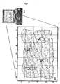
- Optimization and control computing center 230 holds a detailed map of urban area 200.
- the exact locations of the subscribed buildings are marked on the map.
- Figure 4 is an illustration of the detailed map of urban area 200 viewed in the processing unit of optimization and control computing center 230.
- urban area 200 is initially divided into primary sections, e.g. by dividing a city into a grid of squares, and marking the exact location of air pollution monitoring units 210.
- the size of the primary sections may be determined according to the homogeneity of air pollution tendencies in the city: fewer primary sections are needed in a homogenous city because its primary sections are larger.
- the system associates each building 220 with the primary section of urban area 200 to which it belongs.
- the system Based on the data received from monitoring units 210 in real time the system holds data about the air pollution levels in their primary sections, such as in primary sections B2, C4, D-E2 and F3-4.
- the estimation of the air pollution levels in these primary sections is calculated and optimized according to data from all monitoring stations 210 in the urban area, whereas the relative weight of the data received from each station 210 is determined according to its distance from the given primary sections and taking into account other measured factors which are known to influence air pollution levels and diffusion, such as wind direction and speed, temperature, topography, barometric pressure, and humidity levels.
- This process of optimization is performed at the preliminary stage and may be performed periodically during the operation of the system, enabling to estimate actual levels of air pollutions in location which don't include monitoring stations.
- a specific factor is calculated for each possible pair of a primary section and a monitoring station.
- the factor determines the relative influence of each station in relation to the other stations on assessing air pollution tendencies in the primary section.
- the values of factors received from the different monitoring stations are multiplied by the specific factors for each possible pair of a primary section and a monitoring station.
- the received multiplied values from all monitoring stations are then summed up and divided by the sum of the factors in order to determine relative air pollution levels in different primary sections. Since a single or a small number of computing centers 230 may serve urban area 200, the reexamination of calculations, improvement and adjustments of algorithms, the updating of the map of the city and the locations of monitoring stations and the updating of additional parameters may all be performed centrally.
- the mobile monitoring stations may be positioned on a public transportation vehicle, such as a tram or a light-rail.
- the mobile monitoring station follows a regular course throughout the urban area and may transmit air pollution data at preprogrammed time intervals.
- the system utilizes an optimization algorithm for determining optimal times for the ventilation of buildings. To ensure optimized results, and making sure that the buildings are ventilated at the points in time in which there is the minimal air pollution, the system compares the current estimated relative air pollution level at any point in time in the section in which the building resides and compares it with the relative air pollution levels of the last few airflow ventilations of that building. Thus, ventilation commands from the optimization and control computing center may be specific for each section. Determining optimal ventilation times for each building relies on three algorithms: the relevant pollution value of the buildings algorithm, the pollution level of a time unit algorithm and the compromising function. All three algorithms could be updated or changed.
- the relevant pollution value of buildings is defined according to the relative levels of air pollution which were let into the buildings of a specific section during recent ventilations.
- the relevant pollution value of buildings depends on time units between two consecutive measurements.
- the weight of the time unit when outdoor ventilation actually took place in determining the relevant pollution value of buildings depends on the actuality of this time unit. As more ventilation commands are carried out, values of previous time units become less relevant in estimating the current pollution value of buildings.
- the computing center 230 assesses for each section whether or not the present relative pollution value is smaller than or equal to the relevant pollution value of buildings. Ventilation from the outside is activated or continued when the measured values of pollution are smaller or equal to the "relevant pollution value of buildings".
- the system also operates a compromising function.
- This function expresses the required relation between the relevant pollution value of buildings and current level of pollution. According to this function, as time passes from the last ventilation a smaller relation between the relevant pollution value of buildings and the current levels of air pollution is needed in order to initiate ventilation from the outside. Thus, a relatively higher level of pollution is determined as sufficiently low to define current time as a time for ventilation. Once the ventilation in the buildings is activated, the relevant pollution value of those buildings is updated and the compromising function is recalculated.
- Optimal ventilation times could also be determined according to periodic measurements and assessments that predict regular times in which air pollution levels are relatively low such as night hours.
- FIG. 5 is a diagram illustrating the operation of the compromising function.
- Line 500 marks the relative levels of air pollution in the section in which building 220 resides
- sections 510 mark the period of time in which the airflow ventilation regulating unit 240 functioned and activated the airflow ventilation in building 220.
- Line 520 represents the calculated value according to the compromising function, it marks the maximal, level of air pollution in which the airflow ventilation regulating unit 240 may be given a command to start the airflow ventilation.
- the level of line 520 is determined according to the level of the relevant pollution value of buildings in the last ventilations (e.g. points a, c and e).
- line 520 remains constant for a predetermined time span Ti, and then increases gradually as time progresses T 2 .
- the air ventilation regulating unit 240 is given a command to start operating once again.
- the airflow ventilation regulating unit 240 is only given a command to operate in point g since point f is above line 520.
- the compromising function could be updated in relation to different conditions such as different weather conditions in different seasons.
- Figure 6 is a diagram illustrating the levels of air pollution in the buildings in comparison to the air pollution outside the buildings as it is achieved by the algorithm described above.
- Line 500 illustrates the levels of air pollution outside the building and line 600 illustrates the levels of air pollution inside the building.
- Line 610 marks the average value of the air pollution levels outside the building and line 620 marks the average value of the air pollution level inside the building. As it is apparent from the diagram, the average air pollution level outside the building 610 is significantly higher than the average air pollution level inside the building 620.
- Ventilation regulating commands are sent to each client in the section.
- the low priced and simple ventilation regulating mechanism 240 is installed at each client building 220. Commands, such as start or stop, operate the ventilation process in the building. Additionally, the system can send intermediate commands which regulate the extent of ventilation, such as increase or decrease ventilation.
- This system and method improve and reduce the data transference loads on communication pathways between the data gathering points of air pollution levels and other parameters and a large number of ventilation mechanisms.
- the usage of one processing center (the computing center), gathering air pollution data and other parameters from different locations and sources, enables each client to receive simple data, i.e. data already processed into clear data or instructions, from a single source.
- the use of one processing center relieves clients of the need to include a local processing unit.
- This system and method prevents the need to put a professional monitoring station in front of each building and in each section and to integrate numerous processors in every ventilation mechanism of every client.
- This system and method offers only one computing center which determines whether to send commands to a simple regulating unit 240 at each building.
- the computing center identifies patterns or regularities regarding differences in air pollution tendencies between different secondary sections. If such are identified, further efficiency can be achieved by using the same monitoring stations to assess air pollution tendencies in different secondary sections.
- the proportions of the system are as follows: a single to several monitoring stations and a single computing center, whereas a single computer can serve different cities. These facilities may serve up to hundreds of secondary sections and domains per city, and thousands to several million clients.
- the suggested system and method can remotely regulate the activity of different kinds of ventilation systems and air conditioning systems in order to reduce air pollution indoors. It could be adapted and sold as a stand-alone product, as a mechanism that can be integrated in the ventilation and air conditioning systems of clients, or as a built-in mechanism, such as a chip, in production lines of air conditioning and ventilation systems. Therefore the suggested system and method can work with ventilation systems which are not connected to any kind of air conditioning systems.
- the system regulates valves or vents which switch between inner circulation of air and air flow from the outside.
- the ventilation system may be integrated with an alternated valve or vent regulating airflow from the outside.
- FIG. 7 is an illustration of the two states of the airflow in buildings and the operation of the airflow ventilation regulating units.
- the ventilation opening 710 is closed and the air inside the building 720 circulates 730.
- the ventilation opening 760 is open, ventilators are active, and fresh air from the outside 780 flows in 770.
- Airflow ventilation regulating units 240 regulate the state of opening 710, 760. If current air pollution level is found to be equal or lower than the value calculated according to the compromising function, the system sends a command to regulation unit 240 to start, continue or increase the airflow ventilation. Provided that the current air pollution level is found to be higher than the value calculated according to the compromising function, the system sends a command to regulation unit 240 to stop or decrease the airflow ventilation.
- An autonomous ventilation mechanism is designed to ignore air pollution levels outside, and to regulate the flow of fresh air into the building.
- This mechanism contains a timer which can operate outdoor ventilation even when no instructions are received from the control center.
- the autonomous ventilation mechanism can regulate the air flow from the outside.
- These local parameters may include a time limit on the amount of time between two each consecutive airflow ventilation activations.
- the autonomous ventilation mechanism may be programmed to count the time from the last ventilation activation and automatically activate the ventilation after a predetermined time provided that a command from the central computing center was not received. After every_decision of the optimization and control computing center to operate ventilation from the outside, the timer is charged with an additional delay time.
- the delay time is accumulated according to the duration of recent outdoor ventilation determined by the computing center, multiplied by a "delay coefficient" which characterizes the needs of the building. In a building which needs frequent ventilation, a smaller value of the delay coefficient may be determined, thus the delay time is smaller.
- the value of the delay coefficient is determined by the system's technicians during the installation of the system, and the system also defines the limitations of maximal delay time.
- Clients could limit and decrease the delay time programmed in the timer, when they want more frequent outdoor ventilation than usual. Clients are not able to increase the delay time defined by the technicians, but are able to shut down ventilation systems.
- the autonomous ventilation mechanism could be activated not by a timer only, but by another mechanism which is based on indoor CO2 concentrations measured by a sensor integrated in the ventilation systems.
- a small sensor is connected to the ventilation mechanism. The sensor measures the levels of inside the building and informs the autonomous ventilation mechanism when levels exceed a predefined threshold, since relatively high levels of CO 2 indicate that ventilation of air from the outside is needed. The autonomous ventilation mechanism may then activate the airflow ventilation to reduce the levels of inside the building.
- a feedback loop is placed between the computing center 230 and regulating units 240.
- Computing center could receive information regarding airflow ventilation from the regulating unit 240 in every building 220.
- Computing center could also receive information regarding the activity and operation of air pollutant sources inside the enclosed environment such as the operation of cooking equipment. Doing so computing center could examine the efficiency of the operation in specific buildings.
- the computing center could also receive static information such as the size of the building, the primary activity hours in the building, the desirable airflow ventilation frequency of the building and its airflow ventilation rates, and dynamic information relating to the time passed since last ventilation and its length.
- Optimization and control computing center 230 also holds information regarding all airflow ventilation regulating units 240 in every building 220.
- computing center 230 holds its location in the urban area and the type of building in which it is installed.
- Airflow ventilation data regarding each regulating unit includes static information such as the size of the building, the primary activity hours in the building, the desirable airflow ventilation frequency of the building and its airflow ventilation rates, and dynamic information relating to the time passed since last ventilation and its length. According to this data, and according to air pollution fluctuations computing center 230 sends airflow ventilation commands, mainly orders to start or stop the airflow ventilation procedure in the building 220.
- the length of time span Ti and the rate of gradient of T 2 may be determined according to the building static parameters, such as the size of the building, its airflow ventilation capacities, its estimated minimum and maximum population density and the periods of the day in which it is most densely populated.
- the compromising function for a large office building which is expected to be densely populated in midday and in which the ventilation is poor, would be programmed to have a relatively short Ti and a sharp gradient in T 2 during the day, to ensure frequent ventilation when the building is heavily occupied.
- the compromising function for a building with good ventilation rates and medium levels of population density can be programmed to have longer Ti and a more moderate gradient in T 2 .
- the disclosed system may be accommodated to operate for vehicles of any kind, e.g. cars, busses, trains and ships anchored in seaports.
- a global positioning system (GPS) unit or a cellular unit is installed in the vehicle. Every predetermined time interval, the unit transmits the position of the vehicle to the computing center 230.
- Computing center 230 determines whether to ventilate the interiors of the vehicle using air from the outside according to the relevant position of the vehicle in relation to the sections of each urban area as defined by computing center 230.
- computing center 230 switches between ventilation from the outside and circulation according to the measured levels of pollution in the surroundings of the vehicle.
- the calculation results are sent directly to users of the system and not to automated airflow ventilation regulating units 240.
- the position of the user maybe manually determined by the user. Alternatively, the position of the user may be identified according to the geographic location of a cellular mobile device carried by the user, such as a cellular phone, or a GPS unit, according to methods known in prior art.
- the position of the user is transferred to the computing center 230.
- Computing center 230 transmits messages to the users regarding the tendencies in air pollution levels at their current location and the optimal points in time for ventilation. These messages are optionally sent using any type of electronic messaging system in real time such as short messaging service (SMS) messages, instant messages, email messages, multimedia messaging service (MMS) messages and the like.
- SMS short messaging service
- MMS multimedia messaging service
- Users of the system may also receive air pollution data regarding the levels of pollution in different locations and the optimal times for ventilation, in real time, via a dedicated website or query the system using any type of electronic messaging system. Thus users may decide when to ventilate their homes, offices, or wherever they are at any point in time.
Landscapes
- Engineering & Computer Science (AREA)
- Mechanical Engineering (AREA)
- Physics & Mathematics (AREA)
- Business, Economics & Management (AREA)
- General Engineering & Computer Science (AREA)
- Combustion & Propulsion (AREA)
- Chemical & Material Sciences (AREA)
- Economics (AREA)
- Human Resources & Organizations (AREA)
- Strategic Management (AREA)
- Signal Processing (AREA)
- Thermal Sciences (AREA)
- Marketing (AREA)
- Tourism & Hospitality (AREA)
- General Physics & Mathematics (AREA)
- Theoretical Computer Science (AREA)
- General Business, Economics & Management (AREA)
- Entrepreneurship & Innovation (AREA)
- Fluid Mechanics (AREA)
- Game Theory and Decision Science (AREA)
- Life Sciences & Earth Sciences (AREA)
- Atmospheric Sciences (AREA)
- Operations Research (AREA)
- Environmental & Geological Engineering (AREA)
- Fuzzy Systems (AREA)
- Remote Sensing (AREA)
- Quality & Reliability (AREA)
- Development Economics (AREA)
- Radar, Positioning & Navigation (AREA)
- Mathematical Physics (AREA)
- Health & Medical Sciences (AREA)
- General Health & Medical Sciences (AREA)
- Primary Health Care (AREA)
- Air Conditioning Control Device (AREA)
- Ventilation (AREA)
- Investigating Or Analysing Materials By Optical Means (AREA)
Claims (14)
- Verfahren zum Abschätzen von relativen Werten einer Außenluftverschmutzung an verschiedenen Orten innerhalb eines städtischen Gebiets (200) und zum Optimieren der Bedingungen der Belüftung nicht überwachter umschlossener Umgebungen (220) mithilfe von zumindest einer Luftverschmutzungsüberwachungsstation (210) und zumindest einem Rechenzentrum (230), wobei das Verfahren die folgenden Schritte aufweist:in der zumindest einen Luftverschmutzungsüberwachungsstation (210):- Ständiges Erfassen von Außenluftverschmutzungsdaten und Identifizieren täglicher Tendenzen häufiger Außenluftverschmutzungsfluktuationen in routinemäßiger Weise in Echtzeit;- Übertragen der Daten an das zumindest eine Rechenzentrum (230);in dem zumindest einen Rechenzentrum (230):- Identifizieren von Synchronisierungen zwischen verschiedenen Orten des städtischen Gebiets mit Bezug auf Tendenzen der Werte der Außenluftverschmutzung; und- Analysieren der Daten einschließlich eines Abschätzens relativer Werte der Außenluftverschmutzung an zumindest einem Ort desselben städtischen Gebiets, das über keine Überwachungsstation verfügt, auf Basis identifizierter Synchronisierungen der relativen Werte der Außenluftverschmutzungen;- Übertragen der analysierten Daten an eine automatische Regulierungseinheit in zumindest einer umschlossenen Umgebung an Orten in dem städtischen Gebiet, die über keine Überwachungsstation verzügen, wobei sich die analysierten Daten auf relative Echtzeit-Außenluftverschmutzungswerte in der Nähe der nicht überwachten umschlossenen Umgebung beziehen und Befehle für die automatische Regulierungseinheit beinhalten, die die Belüftung der nicht überwachten umschlossenen Umgebung mit Luft von außerhalb betreffen;- wobei die Befehle anhand aktueller Schätzungen von relativen Werten der Luftverschmutzung in der Nähe der nicht überwachten umschlossenen Umgebung im Vergleich zu einem berechneten Schwellenwert des relativen Luftverschmutzungswerts für jeden Ort der umschlossenen Umgebung bestimmt werden; und- wobei der Schwellenwert durch das Rechenzentrum anhand von relativen Werten der Verschmutzung an vorherigen Belüftungszeitpunkten berechnet wird, die in den Berechnungen des Schwellenwerts einer Zeitspanne beinhaltet sind, die ab der letzten Belüftungszeitspanne gemessen wird, wobei die Schwellenwerte umso höher werden, je länger die Zeitspanne ist;- wobei die Befehle die automatische Regulierungseinheit steuern, um eine Belüftung zu aktivieren oder fortzufahren, falls der aktuell geschätzte relative Luftverschmutzungswert kleiner oder gleich dem Schwellenwert ist.
- Verfahren nach Anspruch 1, ferner aufweisend die folgenden Schritte:- Erfassen von Luftverschmutzungstendenzen von einem zweiten Ort in dem städtischen Gebiet; und- Analysieren von Mustern, Regularitäten und Abhängigkeiten mit Bezug auf Differenzen in Luftverschmutzungstendenzen an den Orten desselben städtischen Gebiets durch das Rechenzentrum, wobei die Tendenzen innerhalb derselben Zeitspanne gemessen werden.
- Verfahren nach Anspruch 1, ferner aufweisend die folgenden Schritte:- Kontinuierliches Erfassen von Daten betreffend Interventionsfaktoren von zumindest einem Ort in dem städtischen Gebiet, wobei die Interventionsfaktoren Parameter beinhalten, die die Konzentration, Diffusion und Dispersion von Luftverschmutzung beeinflussen, einschließlich zumindest einem von dem folgenden: der Entfernung zwischen jeder Überwachungsstation und jedem Ort, der Windrichtung, der Windgeschwindigkeit, der Temperatur, der Topographie, dem barometrischen Druck, dem Feuchtewert, den Winkeln oder Vektoren dieser Parameter im Verhältnis zu jedem Ort, der Luftzusammensetzung und der Sonnenlichtintensität;- Übertragen der Daten der Interventionsfaktoren an das Rechenzentrum; und- Abschätzen der Luftverschmutzungstendenzen in Bereichen des städtischen Gebiets, die über keine Überwachungsstation verfügen, in Übereinstimmung mit Daten von entfernten Überwachungsstationen und den Interventionsfaktoren.
- Verfahren nach Anspruch 3, ferner aufweisend den Schritt des Berechnens eines Faktors zum Bestimmen des relativen Einflusses jeder Überwachungsstation auf das Abschätzen der Luftverschmutzungstendenzen jedes Orts, der über keine Überwachungsstation verfügt, wenn die Luftverschmutzungswerte an zumindest zwei verschiedenen Orten desselben städtischen Gebiets überwacht werden, wobei der Faktor für jedes mögliche Paar berechnet wird, das eine Überwachungsstation und einen Ort beinhaltet, wobei der Faktor in Übereinstimmung mit Folgendem berechnet wird: der Entfernung zwischen jeder Überwachungsstation und jedem Ort, der Windrichtung, der Windgeschwindigkeit, der Temperatur, der Topographie, dem barometrischen Druck, den Feuchtewerten, den Winkeln oder Vektoren dieser Parameter im Verhältnis zu jedem Ort oder jeder Geraden zwischen jedem möglichen Paar der Überwachungsstation und einem Ort, der Luftzusammensetzung, und der Sonnenlichtintensität.
- Verfahren nach Anspruch 1, ferner aufweisend die folgenden Schritte:- Messen der Luftbestandteile in der umschlossenen Umgebung;- Einbeziehen der gemessenen Luftbestandteile in der umschlossenen Umgebung in die Berechnung des Schwellenwerts, wobei eine bessere Zusammensetzung der Luftbestandteile in der umschlossenen Umgebung einen niedrigeren Schwellenwert ermöglicht.
- Verfahren nach Anspruch 1, wobei die Datenanalyse nach zumindest einem von dem Folgenden ausgeführt wird:- Vorhersagen der Luftverschmutzungswerte gemäß Vorhersagealgorithmen, wobei die Algorithmen auf einem Lernalgorithmus basieren;- Feedbackinformationen von den umschlossenen Umgebungen.
- Verfahren nach Anspruch 1, wobei die Belüftungsbefehle in Übereinstimmung mit Eigenschaften der umschlossenen Umgebung bestimmt werden, wobei die Eigenschaften zumindest eines von den Folgenden beinhaltet: das Volumen, die Bevölkerung und Aktivitätswerte in der umschlossenen Umgebung, und Feedbackinformationen von der umschlossenen Umgebung, wobei die Berechnungen dementsprechend eingestellt werden.
- System zum Überwachen und Abschätzen relativer Tageswerte der Außenluftverschmutzung innerhalb zumindest eines vorgegebenen städtischen Gebiets (200), und zum Optimieren der Bedingungen der Belüftung nicht überwachter umschlossener Umgebungen (220) an Orten desselben städtischen Gebiets, die keine Außenluftverschmutzungsüberwachungsstation aufweisen, wobei das System Folgendes aufweist:- zumindest eine Luftverschmutzungsüberwachungsstation (210), die sich an Orten des städtischen Gebiets (200) befindet, um kontinuierlich Fluktuationen der Luftverschmutzungswerte an dem Ort routinemäßig zu überwachen;- ein zentralisiertes Optimierungs- und Steuerberechnungszentrum (230) zum Erfassen von Daten der Luftverschmutzung, die von der Überwachungsstation durch ein erstes Kommunikationsnetzwerk (300) empfangen werden, um die Daten zu analysieren und bevorzugte Zeitspannen zum Belüften der nicht überwachten umschlossenen Umgebung mit Luft von außerhalb zu identifizieren, und zum Übertragen von Steuerbefehlen an automatische Regulierungseinheiten von zumindest einer nicht überwachten umschlossenen Umgebung durch ein zweites Kommunikationsnetzwerk (310),- wobei das System nach einem der Verfahren nach Anspruch 1 bis 7 betrieben wird.
- System nach Anspruch 8, wobei zumindest eine zweite Überwachungsstation verwendet wird, um Informationen zu erfassen, die Interventionsfaktoren betreffen, wobei die Interventionsfaktoren Parameter beinhalten, die die Konzentration, Diffusion und Dispersion der Luftverschmutzung beeinflussen.
- System nach Anspruch 8, ferner aufweisend einen Algorithmus, der periodische Messungen und Beurteilungen zum Vorhersagen regulärer Zeitpunkte beinhaltet, an denen die Luftverschmutzungswerte relativ niedrig sind.
- System nach Anspruch 8, ferner aufweisend zumindest eine zweite Überwachungsstation, die zum Zwecke einer vorläufigen Identifikation der Synchronisierungen betreffend die Tendenzen der Luftverschmutzungswerte zwischen verschiedenen Orten desselben städtischen Gebiets betrieben wird.
- System nach Anspruch 8, wobei die zumindest eine zweite Überwachungsstation absolute Luftverschmutzungswerte während begrenzter Zeitspannen misst, was dazu führt, dass die absoluten Luftverschmutzungswerte zu jeder Zeit auf Basis der Korrelation der Luftverschmutzungswerte zwischen verschiedenen Gebieten geschätzt werden können.
- System nach Anspruch 8, wobei die Schätzungen relativer Werte der Luftverschmutzung auf Messungen entfernter Überwachungsstationen basieren.
- System nach Anspruch 8, wobei die Schätzungen relativer Werte der Luftverschmutzung auf Messungen von zumindest einer mobilen Überwachungsstation basieren.
Applications Claiming Priority (2)
| Application Number | Priority Date | Filing Date | Title |
|---|---|---|---|
| US77461006P | 2006-02-21 | 2006-02-21 | |
| PCT/IL2007/000205 WO2007096865A2 (en) | 2006-02-21 | 2007-02-14 | A system and a method for assessing and reducing air pollution by regulating airflow ventiilation |
Publications (3)
| Publication Number | Publication Date |
|---|---|
| EP1987459A2 EP1987459A2 (de) | 2008-11-05 |
| EP1987459A4 EP1987459A4 (de) | 2010-09-15 |
| EP1987459B1 true EP1987459B1 (de) | 2016-09-28 |
Family
ID=38437763
Family Applications (1)
| Application Number | Title | Priority Date | Filing Date |
|---|---|---|---|
| EP07706147.1A Active EP1987459B1 (de) | 2006-02-21 | 2007-02-14 | System und verfahren zum bewerten und reduzieren der luftverschmutzung durch regelung der luftströmungsventilation |
Country Status (8)
| Country | Link |
|---|---|
| US (2) | US8190367B2 (de) |
| EP (1) | EP1987459B1 (de) |
| JP (1) | JP2009527838A (de) |
| KR (1) | KR101470617B1 (de) |
| CN (1) | CN101542266A (de) |
| CA (1) | CA2641366C (de) |
| ES (1) | ES2605941T3 (de) |
| WO (1) | WO2007096865A2 (de) |
Cited By (1)
| Publication number | Priority date | Publication date | Assignee | Title |
|---|---|---|---|---|
| CN107967242A (zh) * | 2017-10-09 | 2018-04-27 | 中国电子科技集团公司第二十八研究所 | 一种城市交通流量对空气质量影响的分析方法及系统 |
Families Citing this family (86)
| Publication number | Priority date | Publication date | Assignee | Title |
|---|---|---|---|---|
| CN101542266A (zh) | 2006-02-21 | 2009-09-23 | G.R.G专利有限公司 | 通过调节气流通风来估计和减少空气污染的系统和方法 |
| US9538657B2 (en) | 2012-06-29 | 2017-01-03 | General Electric Company | Resonant sensor and an associated sensing method |
| US9147144B2 (en) * | 2012-09-28 | 2015-09-29 | General Electric Company | Systems and methods for monitoring sensors |
| US10368146B2 (en) | 2016-09-20 | 2019-07-30 | General Electric Company | Systems and methods for environment sensing |
| US9536122B2 (en) | 2014-11-04 | 2017-01-03 | General Electric Company | Disposable multivariable sensing devices having radio frequency based sensors |
| US9658178B2 (en) | 2012-09-28 | 2017-05-23 | General Electric Company | Sensor systems for measuring an interface level in a multi-phase fluid composition |
| US10914698B2 (en) | 2006-11-16 | 2021-02-09 | General Electric Company | Sensing method and system |
| US9589686B2 (en) | 2006-11-16 | 2017-03-07 | General Electric Company | Apparatus for detecting contaminants in a liquid and a system for use thereof |
| JP2011027308A (ja) * | 2009-07-24 | 2011-02-10 | Hitachi-Ge Nuclear Energy Ltd | 中央制御室の換気方法及び中央制御室換気装置 |
| FR2963972B1 (fr) * | 2010-08-20 | 2012-12-28 | Cairpol | Procede de surveillance et d'expertise d'un systeme et dispositif associe |
| US8542023B2 (en) | 2010-11-09 | 2013-09-24 | General Electric Company | Highly selective chemical and biological sensors |
| DE112013004129T5 (de) | 2012-08-22 | 2015-05-21 | General Electric Company | Drahtloses System und Verfahren zum Messen einer Betriebsbedingung einer Maschine |
| US10598650B2 (en) | 2012-08-22 | 2020-03-24 | General Electric Company | System and method for measuring an operative condition of a machine |
| ES2781873T3 (es) | 2012-08-28 | 2020-09-08 | Delos Living Llc | Sistemas y métodos para mejorar el bienestar asociado con ambientes habitables |
| US9110748B2 (en) * | 2012-09-28 | 2015-08-18 | The Government Of The United States Of America, As Represented By The Secretary Of The Navy | Apparatus system and method of depicting plume arrival times |
| US10684268B2 (en) | 2012-09-28 | 2020-06-16 | Bl Technologies, Inc. | Sensor systems for measuring an interface level in a multi-phase fluid composition |
| CN102878641B (zh) * | 2012-10-11 | 2014-10-15 | 重庆大学 | 一种新风节能控制方法 |
| US10859474B2 (en) * | 2013-02-28 | 2020-12-08 | TricornTech Taiwan | Real-time on-site gas analysis network for ambient air monitoring and active control and response |
| JP2014222116A (ja) * | 2013-05-13 | 2014-11-27 | パナソニック株式会社 | 換気システムおよび制御装置 |
| CN103294028B (zh) * | 2013-05-15 | 2016-05-25 | 韩达光 | 室内建筑能耗和空气质量的综合控制方法 |
| CA2940766A1 (en) | 2014-02-28 | 2015-09-03 | Delos Living Llc | Systems, methods and articles for enhancing wellness associated with habitable environments |
| US20160091474A1 (en) * | 2014-09-29 | 2016-03-31 | Tanguy Griffon | Method and a System for Determining at Least One Forecasted Air Quality Health Effect Caused in a Determined Geographical Area by at Least One Air Pollutant |
| EP3245631A4 (de) | 2015-01-13 | 2018-06-27 | Delos Living, LLC | Systeme, verfahren und artikel zur überwachung und steigerung des menschlichen wohlbefindens |
| FR3031800B1 (fr) * | 2015-01-21 | 2017-01-13 | Aldes Aeraulique | Procede de determination du taux d'encrassement d'au moins un filtre d'un systeme de ventilation et systeme de ventilation associe |
| US10226982B2 (en) * | 2015-04-29 | 2019-03-12 | International Business Machines Corporation | Automatic vehicle climate control based on predicted air quality |
| US10338047B2 (en) * | 2015-06-16 | 2019-07-02 | International Business Machines Corporation | Air-pollution anomaly location mechanism |
| US20160370332A1 (en) * | 2015-06-22 | 2016-12-22 | International Business Machines Corporation | Generating fine resolution air pollution estimates |
| US11226124B2 (en) | 2015-10-09 | 2022-01-18 | The Procter & Gamble Company | Systems and methods for coupling the operations of an air handling device and a volatile composition dispenser |
| US10416687B2 (en) * | 2015-10-09 | 2019-09-17 | The Procter & Gamble Company | Systems and methods for coupling the operations of a volatile composition dispenser and a smart appliance |
| US10830922B2 (en) | 2015-10-28 | 2020-11-10 | International Business Machines Corporation | Air quality forecast by adapting pollutant emission inventory |
| WO2017078413A1 (ko) | 2015-11-02 | 2017-05-11 | 삼성전자 주식회사 | 빔포밍 통신 시스템에서 기준 신호의 송수신 방법 및 장치 |
| WO2017079489A1 (en) | 2015-11-04 | 2017-05-11 | Scepter Incorporated | Atmospheric sensor network and analytical information system related thereto |
| KR101746519B1 (ko) | 2015-11-10 | 2017-06-27 | 주식회사 포스코건설 | 건물 모니터링을 위한 가상 센싱 시스템 및 그 방법 |
| US10438125B2 (en) * | 2015-11-12 | 2019-10-08 | International Business Machines Corporation | Very short-term air pollution forecasting |
| KR101924061B1 (ko) * | 2016-01-07 | 2018-11-30 | 엘지전자 주식회사 | 차량용 보조 장치 및 차량 |
| CN105701952B (zh) | 2016-04-19 | 2019-02-12 | 北京小米移动软件有限公司 | 空气异常告警的方法及装置 |
| US11195125B2 (en) | 2016-04-27 | 2021-12-07 | International Business Machines Corporation | Pollution prediction |
| US9931909B2 (en) * | 2016-07-13 | 2018-04-03 | Toyota Motor Engineering & Manufacturing North America, Inc. | Automated control of vehicle ventilation system |
| WO2018039433A1 (en) | 2016-08-24 | 2018-03-01 | Delos Living Llc | Systems, methods and articles for enhancing wellness associated with habitable environments |
| US11047839B2 (en) | 2016-11-16 | 2021-06-29 | TricornTech Taiwan | Smart sensing network |
| US10976471B2 (en) | 2017-03-07 | 2021-04-13 | International Business Machines Corporation | Post-processing air quality forecasts |
| US10458669B2 (en) | 2017-03-29 | 2019-10-29 | Johnson Controls Technology Company | Thermostat with interactive installation features |
| WO2018191635A1 (en) | 2017-04-14 | 2018-10-18 | Johnson Controls Technology Company | Thermostat with occupancy detection via proxy |
| US10928084B2 (en) | 2017-04-14 | 2021-02-23 | Johnson Controls Technology Company | Multi-function thermostat with intelligent supply fan control for maximizing air quality and optimizing energy usage |
| WO2018191688A2 (en) | 2017-04-14 | 2018-10-18 | Johnson Controls Techology Company | Thermostat with exhaust fan control for air quality and humidity control |
| US10866003B2 (en) | 2017-04-14 | 2020-12-15 | Johnson Controls Technology Company | Thermostat with preemptive heating, cooling, and ventilation in response to elevated occupancy detection via proxy |
| US10837665B2 (en) | 2017-04-14 | 2020-11-17 | Johnson Controls Technology Company | Multi-function thermostat with intelligent ventilator control for frost/mold protection and air quality control |
| WO2018191510A1 (en) | 2017-04-14 | 2018-10-18 | Johnson Controls Technology Company | Multi-function thermostat with air quality display |
| GB2563199A (en) * | 2017-05-11 | 2018-12-12 | Rizzo Claudio | Smart city air cleaning system |
| WO2019046580A1 (en) | 2017-08-30 | 2019-03-07 | Delos Living Llc | SYSTEMS, METHODS AND ARTICLES FOR EVALUATING AND / OR IMPROVING HEALTH AND WELL-BEING |
| US10767878B2 (en) | 2017-11-21 | 2020-09-08 | Emerson Climate Technologies, Inc. | Humidifier control systems and methods |
| US11499954B2 (en) * | 2018-03-06 | 2022-11-15 | Applied Particle Technology, Inc. | Wireless exposure monitor |
| EP3762717A4 (de) * | 2018-03-06 | 2021-11-10 | Applied Particle Technology, Inc. | Drahtloser belichtungsmonitor |
| US11131474B2 (en) | 2018-03-09 | 2021-09-28 | Johnson Controls Tyco IP Holdings LLP | Thermostat with user interface features |
| CN108733881B (zh) * | 2018-04-13 | 2021-10-12 | 同济大学 | 应对公共建筑室内突发空气污染的处理方法 |
| US11371726B2 (en) | 2018-04-20 | 2022-06-28 | Emerson Climate Technologies, Inc. | Particulate-matter-size-based fan control system |
| US12259148B2 (en) | 2018-04-20 | 2025-03-25 | Copeland Lp | Computerized HVAC filter evaluation system |
| US12311308B2 (en) | 2018-04-20 | 2025-05-27 | Copeland Lp | Particulate-matter-size-based fan control system |
| WO2019204779A1 (en) | 2018-04-20 | 2019-10-24 | Emerson Climate Technologies, Inc. | Indoor air quality and occupant monitoring systems and methods |
| US11609004B2 (en) | 2018-04-20 | 2023-03-21 | Emerson Climate Technologies, Inc. | Systems and methods with variable mitigation thresholds |
| US12018852B2 (en) | 2018-04-20 | 2024-06-25 | Copeland Comfort Control Lp | HVAC filter usage analysis system |
| WO2019204788A1 (en) | 2018-04-20 | 2019-10-24 | Emerson Climate Technologies, Inc. | Systems and methods for adjusting mitigation thresholds |
| WO2019204789A1 (en) | 2018-04-20 | 2019-10-24 | Emerson Climate Technologies, Inc. | Indoor air quality sensor calibration systems and methods |
| US11486593B2 (en) | 2018-04-20 | 2022-11-01 | Emerson Climate Technologies, Inc. | Systems and methods with variable mitigation thresholds |
| WO2019204792A1 (en) | 2018-04-20 | 2019-10-24 | Emerson Climate Technologies, Inc. | Coordinated control of standalone and building indoor air quality devices and systems |
| WO2020050174A1 (ja) * | 2018-09-03 | 2020-03-12 | ダイキン工業株式会社 | 換気制御装置及び換気システム |
| US11649977B2 (en) | 2018-09-14 | 2023-05-16 | Delos Living Llc | Systems and methods for air remediation |
| DE102018217610A1 (de) * | 2018-10-15 | 2020-04-16 | Volkswagen Aktiengesellschaft | Verfahren zur Luftqualitätsoptimierung, Steuerung, Fahrzeug und System zur Durchführung des Verfahrens |
| CN111486557B (zh) * | 2019-01-29 | 2024-02-23 | Urecsys-城市生态系统-室内空气质量管理有限公司 | 用于最小化封闭结构中的空气污染的库、系统和方法 |
| US11844163B2 (en) | 2019-02-26 | 2023-12-12 | Delos Living Llc | Method and apparatus for lighting in an office environment |
| US11898898B2 (en) | 2019-03-25 | 2024-02-13 | Delos Living Llc | Systems and methods for acoustic monitoring |
| KR102130497B1 (ko) * | 2019-05-17 | 2020-07-06 | 조흔우 | 실내 오염을 예측하는 실내 공기질 제어 시스템 및 제어방법 |
| KR102189049B1 (ko) * | 2019-07-17 | 2020-12-09 | 주식회사 에코플레이 | 실내 및 실외에서의 오염물질 노출량을 측정하는 방법 및 장치 |
| KR102618721B1 (ko) * | 2019-08-29 | 2023-12-27 | 엘지전자 주식회사 | 공기 청정기 및 이의 동작 방법 |
| US11326800B2 (en) * | 2019-10-17 | 2022-05-10 | Honeywell International Inc. | Apparatuses and methods for air quality maintenance by ventilation based on pollutant forecast |
| CN111554409B (zh) * | 2020-05-27 | 2026-03-20 | 清华大学 | 一种建筑内病毒传播的监测、溯源与预警调控系统及方法 |
| US11565575B2 (en) | 2020-06-30 | 2023-01-31 | Thermo King Llc | Air management system for climate control unit of a transport climate control system |
| US11378299B2 (en) * | 2020-11-04 | 2022-07-05 | Mann+Hummel Gmbh | Metadata driven method and system for airborne viral infection risk and air quality analysis from networked air quality sensors |
| JP7306365B2 (ja) | 2020-11-11 | 2023-07-11 | トヨタ自動車株式会社 | 充電制御システム、充電制御装置および充電制御プログラム |
| JP7322864B2 (ja) | 2020-11-12 | 2023-08-08 | トヨタ自動車株式会社 | 充電制御システム、充電制御装置および充電制御プログラム |
| JP7287378B2 (ja) * | 2020-11-25 | 2023-06-06 | トヨタ自動車株式会社 | 充電制御システム、充電制御装置および充電制御プログラム |
| US20230007082A1 (en) * | 2021-06-30 | 2023-01-05 | Microsoft Technology Licensing, Llc | Pollutant sensor placement |
| CN115901550B (zh) * | 2022-04-01 | 2024-01-09 | 淮安市中证安康检测有限公司 | 一种基于物联网的污染源监测分析系统及方法 |
| US12247965B1 (en) * | 2022-04-22 | 2025-03-11 | Samsara Inc. | Air quality notification system |
| CN115717762B (zh) * | 2022-11-17 | 2024-05-10 | 珠海格力电器股份有限公司 | 空气净化控制方法、装置、空气净化器和交通工具 |
| CN116680518B (zh) * | 2023-08-04 | 2023-10-20 | 北京市智慧水务发展研究院 | 用于地表水环境的时空态势分析方法 |
Citations (2)
| Publication number | Priority date | Publication date | Assignee | Title |
|---|---|---|---|---|
| US6098893A (en) * | 1998-10-22 | 2000-08-08 | Honeywell Inc. | Comfort control system incorporating weather forecast data and a method for operating such a system |
| JP2004028387A (ja) * | 2002-06-24 | 2004-01-29 | Daikin Ind Ltd | 空気調和装置の遠隔管理制御システム及び管理サーバ |
Family Cites Families (18)
| Publication number | Priority date | Publication date | Assignee | Title |
|---|---|---|---|---|
| IT1246618B (it) | 1991-06-14 | 1994-11-24 | Alenia Aeritalia & Selenia | Sistema integrato per il rilevamento dell'inquinamento da traffico urbano e procedimento per detto |
| KR960001248B1 (ko) * | 1991-06-29 | 1996-01-24 | 대한전선주식회사 | 환경오염 정보 관리 시스템 |
| US5831876A (en) * | 1994-08-04 | 1998-11-03 | City Of Scottsdale, An Arizona Municipal Coporation | Method for monitoring regional air quality |
| JPH1178485A (ja) | 1997-09-04 | 1999-03-23 | Zexel Corp | 自動車用空調制御装置 |
| FI110456B (fi) * | 1998-03-09 | 2003-01-31 | Nokia Corp | Järjestelmä ympäristömittausten suorittamiseksi ja mittaustietojen välittämiseksi |
| US6114964A (en) * | 1998-08-28 | 2000-09-05 | Geoenvironmental, Inc. | Systems and methods for fenceline air monitoring of airborne hazardous materials |
| KR20020007544A (ko) * | 2000-07-15 | 2002-01-29 | 송미영 | 대기오염 실시간 모니터링 방법 |
| US6711470B1 (en) * | 2000-11-16 | 2004-03-23 | Bechtel Bwxt Idaho, Llc | Method, system and apparatus for monitoring and adjusting the quality of indoor air |
| US6369716B1 (en) * | 2000-12-01 | 2002-04-09 | Johnson Controls Technology Company | System and method for controlling air quality in a room |
| US7302313B2 (en) * | 2001-02-07 | 2007-11-27 | Aircuity, Inc. | Air quality monitoring systems and methods |
| JP2003025831A (ja) | 2001-07-16 | 2003-01-29 | Denso Corp | 車両用空調装置 |
| KR20040018667A (ko) * | 2002-08-26 | 2004-03-04 | 송미영 | 그리드 기반의 환경오염 예ㆍ경보 방법 |
| US6941806B2 (en) * | 2002-10-31 | 2005-09-13 | Airdat, Llc | Method, apparatus and system for sensing air borne hazardous materials |
| JP2004157898A (ja) * | 2002-11-08 | 2004-06-03 | Mitsubishi Heavy Ind Ltd | 環境監視システム |
| US7331852B2 (en) * | 2003-06-12 | 2008-02-19 | Ezell George D | Method and apparatus for sampling and controlling ventilation airflow into a structure |
| JP2005221107A (ja) | 2004-02-03 | 2005-08-18 | Sanyo Electric Co Ltd | 空気調和装置 |
| US7434413B2 (en) * | 2005-01-10 | 2008-10-14 | Honeywell International Inc. | Indoor air quality and economizer control methods and controllers |
| CN101542266A (zh) | 2006-02-21 | 2009-09-23 | G.R.G专利有限公司 | 通过调节气流通风来估计和减少空气污染的系统和方法 |
-
2007
- 2007-02-14 CN CNA200780006002XA patent/CN101542266A/zh active Pending
- 2007-02-14 KR KR20087023703A patent/KR101470617B1/ko not_active Expired - Fee Related
- 2007-02-14 US US12/280,288 patent/US8190367B2/en active Active
- 2007-02-14 EP EP07706147.1A patent/EP1987459B1/de active Active
- 2007-02-14 WO PCT/IL2007/000205 patent/WO2007096865A2/en not_active Ceased
- 2007-02-14 ES ES07706147.1T patent/ES2605941T3/es active Active
- 2007-02-14 JP JP2008555939A patent/JP2009527838A/ja active Pending
- 2007-02-14 CA CA2641366A patent/CA2641366C/en active Active
-
2011
- 2011-12-12 US US13/323,185 patent/US8666666B2/en active Active
Patent Citations (2)
| Publication number | Priority date | Publication date | Assignee | Title |
|---|---|---|---|---|
| US6098893A (en) * | 1998-10-22 | 2000-08-08 | Honeywell Inc. | Comfort control system incorporating weather forecast data and a method for operating such a system |
| JP2004028387A (ja) * | 2002-06-24 | 2004-01-29 | Daikin Ind Ltd | 空気調和装置の遠隔管理制御システム及び管理サーバ |
Non-Patent Citations (1)
| Title |
|---|
| S.T. LEONG ET AL.: "Air Pollution and Traffic Measurements in Bangkok Streets", ASIAN J. ENERGY ENVIRON., vol. 3, no. 3-4, 2002, pages 185 - 213, Retrieved from the Internet <URL:http://www.asian-energy-journal.info/Abstract/Air%20pollution%20and%20traffic%20measurements%20in%20bangkok%20streets.pdf> [retrieved on 20110822] * |
Cited By (1)
| Publication number | Priority date | Publication date | Assignee | Title |
|---|---|---|---|---|
| CN107967242A (zh) * | 2017-10-09 | 2018-04-27 | 中国电子科技集团公司第二十八研究所 | 一种城市交通流量对空气质量影响的分析方法及系统 |
Also Published As
| Publication number | Publication date |
|---|---|
| US8666666B2 (en) | 2014-03-04 |
| ES2605941T3 (es) | 2017-03-17 |
| EP1987459A2 (de) | 2008-11-05 |
| CN101542266A (zh) | 2009-09-23 |
| EP1987459A4 (de) | 2010-09-15 |
| WO2007096865A2 (en) | 2007-08-30 |
| US20120150353A1 (en) | 2012-06-14 |
| US20090265037A1 (en) | 2009-10-22 |
| KR20090005308A (ko) | 2009-01-13 |
| KR101470617B1 (ko) | 2015-02-10 |
| JP2009527838A (ja) | 2009-07-30 |
| WO2007096865A3 (en) | 2009-04-09 |
| CA2641366C (en) | 2016-04-12 |
| US8190367B2 (en) | 2012-05-29 |
| CA2641366A1 (en) | 2007-08-30 |
Similar Documents
| Publication | Publication Date | Title |
|---|---|---|
| EP1987459B1 (de) | System und verfahren zum bewerten und reduzieren der luftverschmutzung durch regelung der luftströmungsventilation | |
| US11686492B2 (en) | Systems and methods for HVAC filter replacement type recommendation | |
| CN107942960B (zh) | 一种智能化的信息处理系统 | |
| US10551813B2 (en) | Using estimated schedules and analysis of zone temperature to control airflow | |
| US20190011939A1 (en) | Information control system | |
| CN111486557A (zh) | 用于最小化封闭结构中的空气污染的库、系统和方法 | |
| US20120245740A1 (en) | Method and system for controlling environmental conditions of entity | |
| US20250180242A1 (en) | Control kit for building management | |
| US20190195525A1 (en) | Method and apparatus for operating heating and cooling equipment via a network | |
| US12571553B2 (en) | Building air quality assessment | |
| Khan et al. | Application of an occupant voting system for continuous occupant feedback on thermal and indoor air quality–Case studies in office spaces | |
| US20240312330A1 (en) | Systems and methods for on-site pathogen detection | |
| KR20220160271A (ko) | 실내 공기정화 제어를 위한 인공지능 기반 공기질분석시스템 | |
| US20250052734A1 (en) | Building system with air quality assessment sensor configuration model | |
| CN119721320A (zh) | 一种基于边缘计算的楼宇碳计量方法、设备和介质 | |
| Hobson et al. | Occupancy-based predictive control of an outdoor air intake damper: A case study | |
| KR102651256B1 (ko) | 실내공기 살균과 IoT 제어 및 모니터링 기능을 가진 스마트 냉동 공조 시스템 | |
| Gunay et al. | Design of sequences of operation for occupant-centric controls | |
| Yuan et al. | A study towards applying thermal inertia for energy conservation in rooms | |
| KR102817689B1 (ko) | 클라우드 기반 빌딩 에너지 통합관리 시스템 | |
| KR102398410B1 (ko) | 교실 공기질 관리시스템 | |
| Franco et al. | Monitoring of public buildings via energy-efficient Z-Wave wireless sensors | |
| KR102586859B1 (ko) | 탄소중립을 위한 공기질 측정 기반 공조장치 전력사용 관리 시스템 및 그 방법 | |
| Ben-Nakhi et al. | Application of building-dynamics-based control strategies to improve air-conditioning performance in educational buildings | |
| Pistochini et al. | Optimization of Ventilation and Filtration System Operation in Classrooms to Minimize Airborne Infectious Disease Transmission, Particulate Matter Exposure, and Energy Consumption |
Legal Events
| Date | Code | Title | Description |
|---|---|---|---|
| PUAI | Public reference made under article 153(3) epc to a published international application that has entered the european phase |
Free format text: ORIGINAL CODE: 0009012 |
|
| AK | Designated contracting states |
Kind code of ref document: A2 Designated state(s): AT BE BG CH CY CZ DE DK EE ES FI FR GB GR HU IE IS IT LI LT LU LV MC NL PL PT RO SE SI SK TR |
|
| AX | Request for extension of the european patent |
Extension state: AL BA HR MK RS |
|
| 17P | Request for examination filed |
Effective date: 20090303 |
|
| RBV | Designated contracting states (corrected) |
Designated state(s): AT BE BG CH CY CZ DE DK EE ES FI FR GB GR HU IE IS IT LI LT LU LV MC NL PL PT RO SE SI SK TR |
|
| R17D | Deferred search report published (corrected) |
Effective date: 20090409 |
|
| RIC1 | Information provided on ipc code assigned before grant |
Ipc: G01N 7/00 20060101AFI20090515BHEP |
|
| RIC1 | Information provided on ipc code assigned before grant |
Ipc: G01N 7/00 20060101ALI20100726BHEP Ipc: G06Q 10/00 20060101AFI20100726BHEP |
|
| A4 | Supplementary search report drawn up and despatched |
Effective date: 20100812 |
|
| 17Q | First examination report despatched |
Effective date: 20110829 |
|
| DAX | Request for extension of the european patent (deleted) | ||
| RAP1 | Party data changed (applicant data changed or rights of an application transferred) |
Owner name: URECSYS - URBAN ECOLOGY SYSTEMS - INDOOR AIR QUALI |
|
| 17Q | First examination report despatched |
Effective date: 20151116 |
|
| GRAP | Despatch of communication of intention to grant a patent |
Free format text: ORIGINAL CODE: EPIDOSNIGR1 |
|
| INTG | Intention to grant announced |
Effective date: 20160407 |
|
| GRAS | Grant fee paid |
Free format text: ORIGINAL CODE: EPIDOSNIGR3 |
|
| GRAA | (expected) grant |
Free format text: ORIGINAL CODE: 0009210 |
|
| AK | Designated contracting states |
Kind code of ref document: B1 Designated state(s): AT BE BG CH CY CZ DE DK EE ES FI FR GB GR HU IE IS IT LI LT LU LV MC NL PL PT RO SE SI SK TR |
|
| REG | Reference to a national code |
Ref country code: GB Ref legal event code: FG4D |
|
| REG | Reference to a national code |
Ref country code: CH Ref legal event code: EP |
|
| REG | Reference to a national code |
Ref country code: AT Ref legal event code: REF Ref document number: 833321 Country of ref document: AT Kind code of ref document: T Effective date: 20161015 |
|
| REG | Reference to a national code |
Ref country code: IE Ref legal event code: FG4D |
|
| REG | Reference to a national code |
Ref country code: DE Ref legal event code: R096 Ref document number: 602007048073 Country of ref document: DE |
|
| REG | Reference to a national code |
Ref country code: LT Ref legal event code: MG4D |
|
| REG | Reference to a national code |
Ref country code: FR Ref legal event code: PLFP Year of fee payment: 11 |
|
| PG25 | Lapsed in a contracting state [announced via postgrant information from national office to epo] |
Ref country code: LT Free format text: LAPSE BECAUSE OF FAILURE TO SUBMIT A TRANSLATION OF THE DESCRIPTION OR TO PAY THE FEE WITHIN THE PRESCRIBED TIME-LIMIT Effective date: 20160928 Ref country code: FI Free format text: LAPSE BECAUSE OF FAILURE TO SUBMIT A TRANSLATION OF THE DESCRIPTION OR TO PAY THE FEE WITHIN THE PRESCRIBED TIME-LIMIT Effective date: 20160928 |
|
| REG | Reference to a national code |
Ref country code: NL Ref legal event code: MP Effective date: 20160928 |
|
| REG | Reference to a national code |
Ref country code: AT Ref legal event code: MK05 Ref document number: 833321 Country of ref document: AT Kind code of ref document: T Effective date: 20160928 |
|
| PG25 | Lapsed in a contracting state [announced via postgrant information from national office to epo] |
Ref country code: GR Free format text: LAPSE BECAUSE OF FAILURE TO SUBMIT A TRANSLATION OF THE DESCRIPTION OR TO PAY THE FEE WITHIN THE PRESCRIBED TIME-LIMIT Effective date: 20161229 Ref country code: NL Free format text: LAPSE BECAUSE OF FAILURE TO SUBMIT A TRANSLATION OF THE DESCRIPTION OR TO PAY THE FEE WITHIN THE PRESCRIBED TIME-LIMIT Effective date: 20160928 Ref country code: LV Free format text: LAPSE BECAUSE OF FAILURE TO SUBMIT A TRANSLATION OF THE DESCRIPTION OR TO PAY THE FEE WITHIN THE PRESCRIBED TIME-LIMIT Effective date: 20160928 Ref country code: SE Free format text: LAPSE BECAUSE OF FAILURE TO SUBMIT A TRANSLATION OF THE DESCRIPTION OR TO PAY THE FEE WITHIN THE PRESCRIBED TIME-LIMIT Effective date: 20160928 |
|
| REG | Reference to a national code |
Ref country code: ES Ref legal event code: FG2A Ref document number: 2605941 Country of ref document: ES Kind code of ref document: T3 Effective date: 20170317 |
|
| PG25 | Lapsed in a contracting state [announced via postgrant information from national office to epo] |
Ref country code: EE Free format text: LAPSE BECAUSE OF FAILURE TO SUBMIT A TRANSLATION OF THE DESCRIPTION OR TO PAY THE FEE WITHIN THE PRESCRIBED TIME-LIMIT Effective date: 20160928 Ref country code: RO Free format text: LAPSE BECAUSE OF FAILURE TO SUBMIT A TRANSLATION OF THE DESCRIPTION OR TO PAY THE FEE WITHIN THE PRESCRIBED TIME-LIMIT Effective date: 20160928 |
|
| PG25 | Lapsed in a contracting state [announced via postgrant information from national office to epo] |
Ref country code: AT Free format text: LAPSE BECAUSE OF FAILURE TO SUBMIT A TRANSLATION OF THE DESCRIPTION OR TO PAY THE FEE WITHIN THE PRESCRIBED TIME-LIMIT Effective date: 20160928 Ref country code: BE Free format text: LAPSE BECAUSE OF FAILURE TO SUBMIT A TRANSLATION OF THE DESCRIPTION OR TO PAY THE FEE WITHIN THE PRESCRIBED TIME-LIMIT Effective date: 20160928 Ref country code: SK Free format text: LAPSE BECAUSE OF FAILURE TO SUBMIT A TRANSLATION OF THE DESCRIPTION OR TO PAY THE FEE WITHIN THE PRESCRIBED TIME-LIMIT Effective date: 20160928 Ref country code: IS Free format text: LAPSE BECAUSE OF FAILURE TO SUBMIT A TRANSLATION OF THE DESCRIPTION OR TO PAY THE FEE WITHIN THE PRESCRIBED TIME-LIMIT Effective date: 20170128 Ref country code: PT Free format text: LAPSE BECAUSE OF FAILURE TO SUBMIT A TRANSLATION OF THE DESCRIPTION OR TO PAY THE FEE WITHIN THE PRESCRIBED TIME-LIMIT Effective date: 20170130 Ref country code: CZ Free format text: LAPSE BECAUSE OF FAILURE TO SUBMIT A TRANSLATION OF THE DESCRIPTION OR TO PAY THE FEE WITHIN THE PRESCRIBED TIME-LIMIT Effective date: 20160928 Ref country code: PL Free format text: LAPSE BECAUSE OF FAILURE TO SUBMIT A TRANSLATION OF THE DESCRIPTION OR TO PAY THE FEE WITHIN THE PRESCRIBED TIME-LIMIT Effective date: 20160928 Ref country code: BG Free format text: LAPSE BECAUSE OF FAILURE TO SUBMIT A TRANSLATION OF THE DESCRIPTION OR TO PAY THE FEE WITHIN THE PRESCRIBED TIME-LIMIT Effective date: 20161228 |
|
| REG | Reference to a national code |
Ref country code: DE Ref legal event code: R097 Ref document number: 602007048073 Country of ref document: DE |
|
| PG25 | Lapsed in a contracting state [announced via postgrant information from national office to epo] |
Ref country code: DK Free format text: LAPSE BECAUSE OF FAILURE TO SUBMIT A TRANSLATION OF THE DESCRIPTION OR TO PAY THE FEE WITHIN THE PRESCRIBED TIME-LIMIT Effective date: 20160928 |
|
| PLBE | No opposition filed within time limit |
Free format text: ORIGINAL CODE: 0009261 |
|
| STAA | Information on the status of an ep patent application or granted ep patent |
Free format text: STATUS: NO OPPOSITION FILED WITHIN TIME LIMIT |
|
| 26N | No opposition filed |
Effective date: 20170629 |
|
| PG25 | Lapsed in a contracting state [announced via postgrant information from national office to epo] |
Ref country code: MC Free format text: LAPSE BECAUSE OF FAILURE TO SUBMIT A TRANSLATION OF THE DESCRIPTION OR TO PAY THE FEE WITHIN THE PRESCRIBED TIME-LIMIT Effective date: 20160928 |
|
| REG | Reference to a national code |
Ref country code: CH Ref legal event code: PL |
|
| PG25 | Lapsed in a contracting state [announced via postgrant information from national office to epo] |
Ref country code: CH Free format text: LAPSE BECAUSE OF NON-PAYMENT OF DUE FEES Effective date: 20170228 Ref country code: LI Free format text: LAPSE BECAUSE OF NON-PAYMENT OF DUE FEES Effective date: 20170228 |
|
| REG | Reference to a national code |
Ref country code: IE Ref legal event code: MM4A |
|
| PG25 | Lapsed in a contracting state [announced via postgrant information from national office to epo] |
Ref country code: SI Free format text: LAPSE BECAUSE OF FAILURE TO SUBMIT A TRANSLATION OF THE DESCRIPTION OR TO PAY THE FEE WITHIN THE PRESCRIBED TIME-LIMIT Effective date: 20160928 |
|
| PG25 | Lapsed in a contracting state [announced via postgrant information from national office to epo] |
Ref country code: LU Free format text: LAPSE BECAUSE OF NON-PAYMENT OF DUE FEES Effective date: 20170214 |
|
| REG | Reference to a national code |
Ref country code: FR Ref legal event code: PLFP Year of fee payment: 12 |
|
| PG25 | Lapsed in a contracting state [announced via postgrant information from national office to epo] |
Ref country code: IE Free format text: LAPSE BECAUSE OF NON-PAYMENT OF DUE FEES Effective date: 20170214 |
|
| PG25 | Lapsed in a contracting state [announced via postgrant information from national office to epo] |
Ref country code: HU Free format text: LAPSE BECAUSE OF FAILURE TO SUBMIT A TRANSLATION OF THE DESCRIPTION OR TO PAY THE FEE WITHIN THE PRESCRIBED TIME-LIMIT; INVALID AB INITIO Effective date: 20070214 |
|
| PG25 | Lapsed in a contracting state [announced via postgrant information from national office to epo] |
Ref country code: CY Free format text: LAPSE BECAUSE OF NON-PAYMENT OF DUE FEES Effective date: 20160928 |
|
| PG25 | Lapsed in a contracting state [announced via postgrant information from national office to epo] |
Ref country code: TR Free format text: LAPSE BECAUSE OF FAILURE TO SUBMIT A TRANSLATION OF THE DESCRIPTION OR TO PAY THE FEE WITHIN THE PRESCRIBED TIME-LIMIT Effective date: 20160928 |
|
| PGFP | Annual fee paid to national office [announced via postgrant information from national office to epo] |
Ref country code: GB Payment date: 20260213 Year of fee payment: 20 |
|
| PGFP | Annual fee paid to national office [announced via postgrant information from national office to epo] |
Ref country code: ES Payment date: 20260306 Year of fee payment: 20 |
|
| PGFP | Annual fee paid to national office [announced via postgrant information from national office to epo] |
Ref country code: DE Payment date: 20260128 Year of fee payment: 20 |
|
| PGFP | Annual fee paid to national office [announced via postgrant information from national office to epo] |
Ref country code: IT Payment date: 20260219 Year of fee payment: 20 |
|
| PGFP | Annual fee paid to national office [announced via postgrant information from national office to epo] |
Ref country code: FR Payment date: 20260212 Year of fee payment: 20 |