EP1987494B1 - Geräte zum verarbeiten von banknoten in stapeln - Google Patents
Geräte zum verarbeiten von banknoten in stapeln Download PDFInfo
- Publication number
- EP1987494B1 EP1987494B1 EP06819637A EP06819637A EP1987494B1 EP 1987494 B1 EP1987494 B1 EP 1987494B1 EP 06819637 A EP06819637 A EP 06819637A EP 06819637 A EP06819637 A EP 06819637A EP 1987494 B1 EP1987494 B1 EP 1987494B1
- Authority
- EP
- European Patent Office
- Prior art keywords
- banknotes
- transport
- banknote
- sheets
- velocity
- Prior art date
- Legal status (The legal status is an assumption and is not a legal conclusion. Google has not performed a legal analysis and makes no representation as to the accuracy of the status listed.)
- Not-in-force
Links
- 230000007246 mechanism Effects 0.000 claims abstract description 60
- 230000007723 transport mechanism Effects 0.000 claims abstract description 45
- 230000004044 response Effects 0.000 claims abstract description 7
- 230000015572 biosynthetic process Effects 0.000 claims description 16
- 238000000605 extraction Methods 0.000 claims description 11
- 238000000034 method Methods 0.000 claims description 10
- 238000011144 upstream manufacturing Methods 0.000 claims description 6
- 230000001133 acceleration Effects 0.000 claims description 2
- 230000003750 conditioning effect Effects 0.000 claims description 2
- 238000010200 validation analysis Methods 0.000 description 10
- 230000002093 peripheral effect Effects 0.000 description 9
- 238000010586 diagram Methods 0.000 description 4
- 238000000926 separation method Methods 0.000 description 4
- 230000009467 reduction Effects 0.000 description 3
- 239000013536 elastomeric material Substances 0.000 description 2
- 238000003780 insertion Methods 0.000 description 2
- 230000037431 insertion Effects 0.000 description 2
- 230000001360 synchronised effect Effects 0.000 description 2
- 238000003786 synthesis reaction Methods 0.000 description 2
- 241001481828 Glyptocephalus cynoglossus Species 0.000 description 1
- 230000004913 activation Effects 0.000 description 1
- 230000005540 biological transmission Effects 0.000 description 1
- 230000000694 effects Effects 0.000 description 1
- 238000002360 preparation method Methods 0.000 description 1
- 230000008569 process Effects 0.000 description 1
- 230000011664 signaling Effects 0.000 description 1
Images




Classifications
-
- G—PHYSICS
- G07—CHECKING-DEVICES
- G07D—HANDLING OF COINS OR VALUABLE PAPERS, e.g. TESTING, SORTING BY DENOMINATIONS, COUNTING, DISPENSING, CHANGING OR DEPOSITING
- G07D11/00—Devices accepting coins; Devices accepting, dispensing, sorting or counting valuable papers
- G07D11/20—Controlling or monitoring the operation of devices; Data handling
- G07D11/22—Means for sensing or detection
-
- G—PHYSICS
- G07—CHECKING-DEVICES
- G07D—HANDLING OF COINS OR VALUABLE PAPERS, e.g. TESTING, SORTING BY DENOMINATIONS, COUNTING, DISPENSING, CHANGING OR DEPOSITING
- G07D11/00—Devices accepting coins; Devices accepting, dispensing, sorting or counting valuable papers
- G07D11/10—Mechanical details
-
- G—PHYSICS
- G07—CHECKING-DEVICES
- G07D—HANDLING OF COINS OR VALUABLE PAPERS, e.g. TESTING, SORTING BY DENOMINATIONS, COUNTING, DISPENSING, CHANGING OR DEPOSITING
- G07D11/00—Devices accepting coins; Devices accepting, dispensing, sorting or counting valuable papers
- G07D11/10—Mechanical details
- G07D11/14—Inlet or outlet ports
-
- G—PHYSICS
- G07—CHECKING-DEVICES
- G07D—HANDLING OF COINS OR VALUABLE PAPERS, e.g. TESTING, SORTING BY DENOMINATIONS, COUNTING, DISPENSING, CHANGING OR DEPOSITING
- G07D11/00—Devices accepting coins; Devices accepting, dispensing, sorting or counting valuable papers
- G07D11/50—Sorting or counting valuable papers
Definitions
- the present invention relates to an equipment for processing banknotes in stack.
- the invention relates, more specifically, to an equipment and a method for processing banknotes in stack, for instance for a banking deposit, which provides individual transport of the banknotes and includes a receiving section for receiving in superimposition the transported banknotes.
- Equipments for processing banknotes in stack are known, for instance in the use as automatic teller machines for banking deposit which form, in the inside, bundles of piled banknotes which are moved in unitary way. These equipments provide unstacking or separating operations of the deposited stack of banknotes, the check of the sheets constituting the stack and the validation of the banknotes. It follows the formation of a bundle of the not recognized sheets, to be returned to the customer and the formation of a bundles or sub-stack of the validated banknotes, to be separated and to be further validated, for a deposit in account and transfer in a safe, or for the return to the customer in the case of afterthought.
- This equipment comprises, as receiving section, a box assembly with two storage boxes, which is movable in height for receiving banknotes and components not recognized and forming respective bundles or sub-stacks.
- the box assembly is further shifted for positioning the sub-stacks of banknotes and components not recognized in different areas of the equipment on following operative steps.
- a problem of the equipments which process, as wholes, bundles or sub-stacks of banknotes and other overlapped sheets relates to the fact that the formation of the sub-stacks presents risks of jams, which can not be solved by the customer and could put the equipment out of use for the following customers.
- the drawbacks are particularly evident, when the deposited, stack comprises worn-out banknotes, banknotes of different dimensions and/or in the case in which the number of the banknotes to be processed is high with respect to the available spaces.
- the remedies can provide the lowering of the operational speed, the reduction of the maximum number of banknotes in the stack, and/or the use of complex stacking mechanisms.
- Object of the present invention is an equipment and a method for processing banknotes in stack, having high operational speed and great reliability also in presence of worn-out banknotes.
- Another object of the invention is an equipment for processing banknotes in stack of different dimensions, in detail the banknotes of the European system, which is fast and reliable and of reduced dimensions and which has a relatively high capability of processing.
- an equipment for processing banknotes in stack for instance for a banking deposit, including a transport mechanism for individually transporting banknotes- or similar sheets, and a receiving section for receiving, in superimposition, transported banknotes or sheets.
- the equipment further comprises an interface mechanism with nipping members interposed between a section of the transport mechanism and the receiving section.
- Electronic control circuits are operative on the interface mechanism for slowing down the banknotes or sheets at the input of the receiving section in order to make easy a regular piling of the banknotes or sheets.
- the nipping members are engageable with the banknotes or sheets outgoing from the said section of the transport mechanism for their transport at a velocity (Vb, Vr) reduced with respect to the transport velocity (Vt) and the electronic circuits control the interface mechanism in response to the information of transit of the banknotes or sheets.
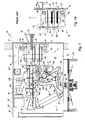
- an equipment for the automatic deposit of banknotes of the type described in the above-mentioned European patent application EP 1 544 806 is represented with 22, the components with identical function maintain a same denomination.
- the banknotes 23 to be deposited are assembled in a stack 24 and, after automatic validation, are provided for being transferred in a store-safe 26 underlying the equipment 22, with accredit of the respective values to a customer account.
- the equipment 22 includes a containing structure 32, of parallelepiped shape, with a transaction port 33 and, inside, a separating device 36, a validation device 37, a transport mechanism having a section 38 and a section 39, respectively upstream and downstream of the validation device 37, an electronic processing unit 40 and a box assembly 52.
- a shutter door 46 for the transaction port 33 and a servomechanism are mounted on a front 41 of the structure 32.
- an opening 44 at the input of the store-safe 26 is provided.
- the insertion of the stacks 24 and the moving of the single banknotes occur along the longitudinal sense of the banknotes.
- a frame 47 supports the various devices and mechanisms of the equipment 22.
- the validation device 37 analyzes the moving sheets separated by the device 36, recognizing the banknotes validated for the deposit and the non-acceptable constituting sheets.
- the separating device 36 and the section 39 of the transport mechanism are spaced away from the front 41 and delimit a passage space 51.
- the box assembly 52 is lodged in the space 51 and has possibility of shifting in vertical between three positions or operational levels.
- the box assembly 52 includes a banknote box 53 and a discard box 54 arranged at different heights, respectively upper and lower, which define corresponding receiving sections for overlapped bundles of banknotes and other sheets.
- the box 53 receives the stack 24 of the banknotes presented by the customer for the deposit and, in a following step, the validated banknotes separated from the stack, as sub-stack banknote sub-stack 50 ( Fig. 1a ).
- the box 54 receives the sheets and the other refused components as discard sub-stack 55.
- a moving mechanism 60 and two holding mechanisms 61 and 62 ( Fig. 2 ), move the stack 24 or the sub-stacks 50 and 55 ( Fig. 1 a) in a step of introduction and in association with a temporary acceptance of the sheets constituting the stack.
- the moving mechanism 60 and the holding mechanisms 61 and 62 are actuatable by a motor 131 and by respective motors 136 and 137 controlled by the processing unit 40 ( Fig. 1 ).
- a motor 177 also controlled by the processing unit 40, actuates a vertical shifting mechanism for the box 52 as described in the cited European patent application EP 1 544 806 .
- a first position "I" of the block 52 is functional to the deposit of the stack 24 in the transaction port 33 and to the return to the customer.
- a second lower position "II”, shown in Fig. 1a concerns particular steps of the procedure of deposit and a third higher position, not shown, is functional to the return of the discards.
- the section 39 of the transport mechanism ( Fig. 1 ) is designed for moving the banknotes and the other sheets outputted from the device 37 along a common path 69. From the path 69 the sheets constituting the stack are directed toward a path of deposit-capture 71 or toward a path for recognized banknotes 72 or toward a path for constituting sheets not recognized 73.
- the path of deposit-capture 71 is directed toward the opening 44 for the store safe 26, whilst the path 72 and the path 73 are direct toward the box assembly 52.
- the paths 72 and 73 have output sections arranged at different height and in a condition of substantial vertical coplanarity and are respectively functional to the formation of the sub-stacks 50 and the sub-stacks 55. Diverters controlled by electromagnets, in turn controlled by the processing unit 40, effect the selection of the paths.
- photoelectric couples photo-emitter and photo-sensor
- Photoelectric couples "H” and “I” for the separating device 36, and a photoelectric couple “L” at the input of the section 38 of the transport mechanism are provided.
- photoelectric couples "Q” and “R” are arranged at the final portion of the output sections of the paths 72 and 73 and a couple "S" is common to the inputs of the passage space 51.
- the box assembly 52 At rest, the box assembly 52 is in the position "I" ( Fig. 1 ) with the banknote box 53 adjacent to the transaction port 33.
- Activation of the equipment 22 by a customer causes the opening of the door 46.
- the stack 24 introduced in the transaction port 33 partially engages the box 53.
- the program actuates in sequences the holding mechanisms for the stack 24, the moving mechanism for the block 52 and the servomechanism of the door 46, with complete transferring of the stack 24 in the box 53 and closing of the door.
- the program causes the stack 24 to move to the separating device 36, and the box assembly 52 to be positioned in the position "II" ( Fig. 1a ).
- the banknote box 53 is now arranged in front of the output section of the path 72 for receiving the recognized banknotes, whilst the discard box 54 is in front of the output section of the path 73 for receiving the unrecognized constituting sheets.
- the stack 24 is separated and the single constituting sheets pass one after the other in front of the validation device 37.
- the electromagnets of the various diverters are selectively activated and the section 39 of the transport mechanism singly move the banknotes and the other constituting sheets along the common path 69 and, in alternative, along the paths 71 or 72 or 73.
- the validated banknotes of the path 72 are piled to form the bundle or banknote sub-stack 50 in the box 53 (see Fig. 1 a) .
- the constituting sheets not recognized of the path 73 as generic sheets or, typically, the banknotes recognized as worn-out, are also piled and form the bundle or discard sub-stack 55 in the box 54.
- the processing unit 40 proceeds with a restitution step, in which the box assembly 52 is moved to the highest position, the door 46 is opened and the discard sub-stack 55 is moved in the transaction port 33 for the withdrawal of the constituting sheets not recognized.
- the box assembly 52 is carried back in the position "I", and the moving mechanism moves the sub-stack 50 of the validated banknotes in the device 36 for another separation operation.
- the single banknotes are further validated and the respective values accounted and accredited, whilst the transport mechanism moves the banknotes in the store-safe 26, along the path 71 and through the opening 44.
- the box assembly 52 For the restitution of the validated banknotes, on request of the customer, the box assembly 52 is carried in the position "I", the door 46 is opened and the sub-stack 50 is moved in the transaction port 33 for the withdrawal.
- the box assembly 52 ( Figs. 1 and 2 ) has a frame of substantially parallelepiped shape of vertical extension with two sides 128 and 129, open on the front and on the back and includes three couples of endless conveyer belts 132, 133 and 134 actuated by the moving mechanism 60.
- the belts 132, 133 and 134 extend horizontally and their upper and lower branches are longer than the maximum length of the acceptable banknotes.
- the upper and lower branches of each couple are substantially coplanar and, transversally, the branches are spaced away a distance such to receive, with safety, all the typologies of acceptable banknotes to be deposited.
- the couples of belts 133 are interposed between the banknote box 53 and the discard box 54, whilst the couples 132 and 134 are respectively arranged at a higher surface in the box 53 and on a lower surface in the box 54.
- the lower branches of the belts 132 are arranged above the upper branches of the belts 133, whilst the upper branches of the belts 134 are below the lower branches of the belts 133.
- the holding mechanisms 61 and 62 are provided for moving in height the couples of belts 132 and 134 with respect to the couple 133, varying the mutual distance therebetween.
- a configuration of minimum distance is designed for the taking of a stack or a sub-stack, to form a unitary set for the following shifting.
- a configuration of maximum distance provides, in the position "II" of the block 52, to receive the banknotes and the other components in optimal conditions for the formation of the sub-stacks 50 and 55.
- the endless couple of belts 133 is in engagement with respective rollers supported in a median section of the box assembly 52.
- the endless couples of belts 132 and 134 are in engagement with other rollers, which are vertically supported in the rotation by shiftable platforms by the holding mechanisms 61 and 62.
- a motor 131 of the moving mechanism 60 actuates motor rollers of the rollers engaging the couples of belts 132, 133 and 134.
- the box 53 is adjacent to the final section of the path 72 to receive the recognized banknotes.
- the box 54 is adjacent to the final section of the path 73 to receive the constituting sheets not recognized, whilst the holding mechanisms 61 and 62 hold the belts 132 and 134 spaced away from the couple 133.
- the section 39 of the transport mechanism moves the validated banknotes in the box 53 and the constituting sheets not recognized in the box 54, forming the banknote sub-stack 50 on the belts 133 and the discard sub-stack 55 on the belts 134.
- the processing unit 40 actuates the holding mechanism 62 of the box 54, lifting the belts 134 to arrest the sub-stack 55 against the belts 133. Then, the unity 40 actuates the vertical shifting mechanism, lifting the block 52 up to the position, not shown, in which the discard box 54 is adjacent to the transaction port 33 and the banknote box 53 is above thereto. In a return step, the processing unit 40 actuates the mechanisms 60 and 62 to move the discard sub-stack 55 toward the transaction port 33 and spacing away the belts 134 for the restitution.
- the separating device 36 includes a motor 184, a couple of conveyer belts 186 actuated by the motor 184, a series of separating rollers 202 and refusal rollers 203, a separating motor 204 of actuation for the rollers 202 and a pressure member 206.
- the conveyer belts 186 support the stack 24 or the sub-stack 50, 55 in contrast with the pressure member 206 and, upon actuation, advance the stack or sub-stack, or the lower component sheet thereof.
- the separating rollers 202 are continuously rotated in the sense of the separation, whilst the refusal rollers 203 are interposed with interference between the rollers 202 and are rotated in opposite sense for avoiding double feeding of the banknotes or sheets, in a manner known per sé.
- the sections 38 and 39 of the transport mechanism present two couples of transport endless belts 216 and, respectively, 217, and in which the belts are arranged side by side on guide rollers of the frame 47.
- the banknotes 23 are held by the transport belts or are followed in the movement by a couple of contrast belts 219 of the section 38 and by three couples of contrast belts 221, 222 and 223 of the section 39.
- the transport belts and the contrast belts are substantially put in synchronism and at a constant at velocity Vt, through toothed belts not shown in the drawings, by a transport motor 218.
- the banknotes are consequently transported at the same velocity Vt.
- the movement of the banknotes and the discards toward the boxes 53 and 54, along the final sections of the paths 72 and, respectively 73, is effected by two couples of opposite rollers 231 and 232, kept in rotation by the motor 218 with peripheral velocity synchronous with the velocity of the belts 217.
- the couples of rollers 231 and 232 are protected by a wall 233 and are adjacent to windows 234 and 236 at different height.
- the cells 52 and 53 are in front of the couples of rollers 231 and 232, and the windows 234, to form the sub-stacks 50 and 55 above the upper branches of the belts 133 and 134.
- the piling of the banknotes and the other components generally occurs after a strike of the leading edges against the front 41 of the structure 42 and the components of smaller length are subject to dispose the trailing edges advanced with respect to the trailing edges of the other ones.
- the sub-stacks are of high thickness, it represents a risk of interference for the following incoming banknotes. The risk is well greater when the incoming banknote is worn-out and the last piled banknote has its trailing edge folded upward.
- the irregularities of piling are also source of problems in the following steps of transport and separation of the sub-stacks.
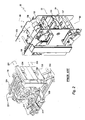
- An equipment for processing banknotes in stack according to the invention is represented with 281 in figure 3 .
- This equipment 281 solves the problems connected with the stacking of the banknotes and other sheets from the deposited stack, without substantial reduction of the operational speed.
- banknotes will be used both for the true banknotes and for other component sheets of a stack and sub-stack.
- the equipment 281 is similar to the equipment 22 of Fig. 1 , but presents differences in the section 39 of the transport mechanism, herein represented with 282 and, specifically, in the path of deposit-capture 72 and the path of recognised banknotes 73, herein represented respectively with 283 and 284.
- the separating device 36 includes, inter alia, a wall 285 with a lower slot between the transport belts 186 and the separating rollers 202, an extraction roller 286, and a pinch roller 287, and in which the rollers 286 and 287 are downstream of the separating rollers 202.
- the motor 204 is connected with the rollers 202 and 286 through a free-wheel mechanism and it is controlled by the processing unity 40 for a continuous rotation of the rollers with a peripheral extraction velocity Ve.
- the photoelectric couple "H” is arranged upstream of the rollers 202 and the refusal rollers 203, adjacent to the wall 285, whilst the photoelectric couple “I” is downstream of the rotters 286 and 287.
- the processing unit 40 uses the signals from the photoelectric couple "H”, preliminarily to the separating operation, for actuating the motor 184 in order to advance the stack or sub-stack of banknotes up to the wall 285.
- the signals of the couple "I" are used for the control of the separating operation,
- the motor 184 make the lower banknote to advance through the lower slit; the stack or sub-stack is arrested by the wall 285, whilst the rollers 202 and 286 extract the ' lower banknote underneath the stack or sub-stack
- the unit 40 arrests the motor 184 when the leading edge of the separated banknotes crosses the photoelectric couple "I".
- the banknote continues to be extracted by the rollers 202 and 286, going in engagement with the belts 216 and the contrast belts 219 of the transport mechanism.
- the peripheral velocity Ve of the rollers 202 and 286 is less of the transport velocity Vt but the free-wheel mechanisms allow the banknote and the rollers to accelerate whilst the banknote is still engaged with the same rollers 202 and 286.
- the processing unit 40 On signalling of the photoelectric couple "I" the processing unit 40 actuates again the motor 204 to separate a new banknote, when the trailing edge of the extracted banknote has completely disengaged the rollers 286 and 287.
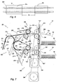
- the settings of the separating device 36 and the transport mechanism are such to define a safety distance ⁇ e between the trailing edge of a banknote 23n and the leading edge of a following banknote 23n+1. It is schematized in Fig. 6 , with reference to the condition in which the banknotes are engaged by the belts and the contrast belts for the transport.
- the distance ⁇ e is also functional to ensure that the movement of actuation of the diverters occurs, without obstacles or jams, between a banknote and the following one and with a correct addressing, on the flight, toward the paths 283, 284 or 71.
- the equipment 281 ( Figs. 3 and 7 ) comprises interface mechanisms 289, 291 with nipping members to move the banknotes in output by the transport mechanisms and electronic circuits 292 of control for the mechanisms 289 and 291 for slowing down the banknotes outgoing from the transport mechanism at the input of the receiving sections.
- the nipping members of the mechanisms 289, 291 are interposed between the output sections of the paths 283 and 284 and the inputs of the passage space 51; the electronic circuits 292 respond to information of transit of the banknotes for reducing the output velocity to a minimum value, optimal for the stacking.
- the transport mechanism operates in continuous way, with velocity servo-control for a relatively high value of the transport velocity Vt.
- the slowing down of the banknotes in output by the interface mechanisms 289, 291 does not reduce the overall velocity; of the equipment 281.
- the deceleration of the banknote is limited for being less than a spacing time ⁇ t, of transit between the trailing edge of a banknote 23n and the leading edge of a following banknote 23n+1, at the output of the paths 283 and 284.
- This spacing time ⁇ t corresponds to the ratio ⁇ e/Vt between the safety distance ⁇ e and ( Fig. 6 ) and the transport velocity Vt.
- the method to form the stacks or sub-stacks provides the steps: a) setting the nipping members of the interface mechanism to receive a banknote from the transport mechanism at its transport velocity; b) actuating the nipping members to slow down the banknote disengaged from the transport mechanism up to a predetermined minimum velocity; c) disengaging the banknote from the nipping member for the superimposition on the stack or sub-stack in formation; and d) conditioning the nipping members to receive a following banknote to be stacked.
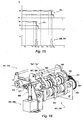
- the interface mechanisms 289, 291 ( Figs. 3 , 7 and 10 ) comprise respective motors 293, 294 controlled by the circuits 292.
- the nipping members include couples of output rollers 296, 297, identical each the other, which are respectively connected in the rotation with the motors 293, 294, for instance through gears and toothed belts.
- each couple of rollers 296, 297 includes a motor shaft 298 and a shaft 299, parallel each the other, spaced away vertically and having couples of terminal rollers 301 and 302.
- the motor shafts 298 are mounted on the frame 47 and are rotated by the motors 293, 294 through the pulleys and toothed belts; the shafts 299 are supported by respective oscillating frames 303 and are inclined toward the motor shafts 298 by strong load springs not shown in the drawings. It should be clear that, in alternative, also the shafts 299 could be connected in the rotation with the motors 293, 294.
- Each block 304 defines a central roller 306 with lateral hubs, which supports two other rollers 307 and 308.
- the rollers 307 and 308 are in elastomeric material and have a diameter larger of the one of the central roller 306.
- Each block 309 defines a central roller 311 of greatest diameter and two lateral rollers 312 and 313.
- the central rollers 311 are symmetrically arranged above the rollers 306, whilst the lateral rollers 312 and 313 are arranged above the rollers in elastomeric material 307 and 308.
- the structure above described causes a transversal deformation of the banknotes 23n, substantially as a Greek profile evidenced in Fig. 5 .
- the longitudinal rigidity of the banknotes is substantially increased, with reduction of the deformations in the following steps of formation of the sub-stacks, also in the case of worn-out banknotes.
- the paths 283 and 284 of the section of transport 282 are defined in the terminal portion by motor rollers 318, 319 and pinch rollers 321, 322.
- the motor rollers 318, 319 are in engagement with the portions of the transport belts 221 and 223 adjacent to the outputs toward the boxes 52 and 53, whilst the pinch rollers 321, 322 are in engagement with preceding portions of the belts 221 and 223.
- the rollers 321 and 322 define nipping areas 323 and 324 with the belts 221 and 323, downstream of the diverters 224 and 226 and upstream of the couples of output rollers 296 and 297.
- nipping areas represent the last area of engagement of the transport mechanism 282 with the banknote to be stacked.
- Guide elements not numbered in the drawings, support and guide the banknotes between the areas of contact 323 and 324 and the couples of output rollers 296 and 297.
- the motors 293 and 294 are, for instance, of stepping type and the electronic circuits 292 drive the motors in response to information regarding the disengagement of the banknotes from the nipping areas 321 and 322 along the paths 283 and 284.
- two photoelectric couples "Q1" and “R1” are provided which sense the banknotes in transit.
- the couples "Q1" and “R1” are arranged downstream of the nipping areas 323 and 324, adjacent to the motor rollers 318 and 319 and at a distance ⁇ b1 ⁇ b2 from the areas of engagement of the output rollers 296, 297.
- Two photoelectric couples "S1" and “S2” are arranged closely downstream of the couples of rollers 296 and 297, adjacent to the windows 234 and 236, and recognize the passage of the banknotes through the inputs of the passage space 51.
- the circuits 292 drive the motors 293 and 294 to maintain the output rollers 296 and 297 at a peripheral velocity synchronous with the transport velocity Vt (see also Figs. 10 and 11 ).
- a banknotes 23n leaving the area of contact 323, 324 is engaged by the rollers 296 or 297 to be transported at the velocity Vt and at a time "t0", and progressively projecting in the passage space 51.
- the banknote 23n moves at the velocity Vt, up to a time "t1" in which the couple photoelectric "Q1", "R1" signals the passage of its trailing edge. Then, the circuits 288 quickly slow down the motor 293, 294, braking the banknote up to a minimum velocity Vb at a time "t2". The banknote further projects in the passage space 51 and disengages from the rollers 296, 297.
- the banknote 23n crosses, by inertia, the window 234, 236 at the minimum velocity Vb, falling in the lower sub-stack 50, 55 with the trailing edge adjacent to the wall 233.
- the circuits 292 maintain actuated the motor 293 or 294 for the condition of transport at the velocity Vb.
- banknote 23n+1 will be engaged by the output rollers 296 or 297 at the velocity Vt, without problems, at a time "t'0" > "t4", it will begin to slow down at the time "t'1", and will reach the minimum velocity Vb at the time "t'2".
- the circuits 288 will control in turn the motor 293, 294 in the above-described manner.
- the interface mechanisms 289 and 291 execute the steps: a) engagement of the nipping members with the banknote in transit in synchronism with the section 282 of the transport mechanism, up to the disengagement from the transport mechanism; b) deceleration of the nipping members up to the predetermined minimum velocity of the banknote; c) disengagement of the banknote from the nipping members of the stacking mechanism for the stacking therof on the stack in formation; and d) acceleration of the nipping members for the engagement, in the condition of synchronism with the following banknote to be stacked.
- the area of banknote 23n interested to the taking for the deceleration depends in length on the distance ⁇ b1, ⁇ b2 between the photoelectric couples and the rollers 292, 293. This area can vary between a value Bmin and a value Bmax, ( Fig. 12 ) in dependence on various factors, as fluctuations of the transport velocity Vt and inclination of the banknotes with respect to the photoelectric couples.
- the circuits 292 ( Fig. 10 ) can be programmed so to determine a gradual deceleration of the motors 293, 294, for slowing down, without vibrations, the banknotes in output.
- the dimensional differences or of state of the banknotes and the differences of response of the interface mechanisms do not modify the conditions of stacking.
- the variations of the nipping areas cause only a variation of the interval of time during which the banknote maintains the minimum velocity before the disengagement from the output rollers, without any consequence in the formation of the stacks.
- the minimal braking velocity Vb ( Figs. 7 and 11 ) can be particularly low, sufficient to the disengagement of the tails of the banknotes from the output rollers 296, 297 and from the windows 234 and 236.
- This velocity can be included between a value next to zero and a value equal to the 50% of the transport velocity Vt.
- the velocity Vb is included in the field between 0,2Vt and 0,4Vt.
- the equipment 329 includes two extraction mechanisms 331 and 332, associated with the interface mechanisms 289 and 291 and actuatable to facilitate the separation and the removal of the trailing edges of the banknotes to be stacked from the windows 234 and 236.
- the extraction mechanisms 331 and 332 comprise two respective shovel levers 333 and 334 and electromagnets 336 and 337 controlled by the circuit 292 (see Fig. 10 ).
- the shovel levers 333 and 334 have a substantially "T" shape and longitudinally extend for a good portion of the boxes 53 and 54.
- Each shovel lever has a central portion interposed between the belts 132 and 133, a conventionally front portion 338, 339, direct toward the wall 233 and a rear portion of fulcrum on the box assembly 52.
- the shovel levers 333 and 334 are connected with the electromagnets 336, 337 through advantages 343 and are opposed by return springs generically represented by an arrow "F".
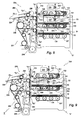
- the return springs In condition of rest and in the configuration "II" of Fig. 8 , the return springs maintain the shovel levers 333, 334 in horizontal position few underneath the belts 132 and 133, and above the windows 234 and 236.
- the impulsive actuation of an electromagnet 336, 337 causes a quick counter-clockwise rotation in sense of the shovel lever 333 334 with lowering of the portion 338, 339, underneath the window 234, 236 and, for instance, above the sub-stack 50, 55 in formation.
- the circuits 292 actuate the electromagnet 336, 337, in response to signals from the photoelectric couple "S1", “S2" ( Figs. 8 and 9 ) associated with the passage of the trailing edge of the banknote 23n disengaged from the output rollers 296, 297.
- the tail of the banknote is quickly removed from the window 234, 236, as shown in Fig. 9 , and lowered along the wall 233, whilst the banknote overlaps in orderly way on the sub-stack 50, 55, for the stacking.
- the equipments according to the invention ensure the processing of 8-10 banknotes/sec.
- the velocity of extraction is included between 0,5 and 2,5 m/sec and the safety distance ⁇ e between the edges of the banknotes is between 20 and 80 mm.
- the velocity Vt of the transport mechanism has a substantially constant and relatively high value of 1ö2 m/sec.
- a further embodiment of the equipment for processing banknotes in stack of the invention, represented with 350 is partially shown in the figures 13 and 15 .
- the equipment 350 includes components identical to the ones of the equipment 281 or 329, interface mechanisms 351 and 352 and electronic control circuits 353, different but similarly predisposed for slowing down the banknotes or sheets outgoing from the transport mechanism at the input of the receiving sections.
- the interface mechanisms 351, 352 include respective electromagnets 354, 356 and, as nipping members, couples of output rollers 357, 358, identical each the other and interposed between the output sections of the paths 283 and 284 and the windows 234 and 236.
- the output rollers are connected in the rotation with the transport motor 218 and are actuatable for the condition of deceleration of the banknotes by the electromagnets 354, 356.
- Each couple of output rollers 357, 358 ( Fig. 16 ) has a motor shaft 359 with dragging rollers 361 and a shaft 362 with pinch rollers 363, parallel each the other and vertically spaced away.
- the motor shaft 359 is rotatable on the frame 47 and on this shaft is keyed a gear 364 in engagement with the toothed belts of the transport mechanism, not shown in the drawings.
- the above-mentioned mechanism is designed so that the peripheral velocity of the dragging rollers 361, represented with Vr, is a fraction of the velocity of transport of the transport mechanism.
- the peripheral velocity Vr is included between 0,2Vt and 0,6Vt.
- the shaft 362 ( Figs. 13 and 16 ) is idle rotatable on a swinging frame 366 connected with the mobile component of the electromagnet 354, 356.
- the frame 366 is shiftable between a condition of disengagement in which the pinch rollers 363 are spaced from the dragging rollers 361 and a condition of engagement in which the pinch rollers 363 are in taking with the dragging rollers 361.
- the frame 366 is in the condition of disengagement.
- the transport of a banknote outgoing from the path 283, 284 at the velocity Vt and still in taking with the transport belts will be not disturbed by the rollers 361 rotating at the reduced peripheral velocity Vr.
- the interface mechanisms 351 and 352 execute the steps: a) transit of the banknotes outgoing from the section 282, 284 through the spaced nipping members at the velocity of synchronism and disengagement of the banknotes from the transport mechanism; b) actuation of the nipping members with deceleration of the banknotes up to the predetermined minimum velocity; c) disengagement of the banknotes from the nipping members for the piling on the stacks in formation; and d) de-actuation of the nipping members for the transit of the following banknote at the velocity of synchronism.
- the equipment 350 can comprise mechanisms for the dynamic stiffening of the banknotes associated with the interface mechanisms 351 and 352.
- couples of draw members 367, 368 could be provided, substantially identical to the couples of output rollers 296, 297 of the equipment 281.
- These members include a motor shaft 369 and a shaft 371, parallel each the other and vertically spaced away.
- the motor shafts 369 are rotatable on the frame 47 and carry drawing blocks; whilst the shafts 371 carry corresponding contrast blocks and are supported by oscillating frames 372 inclined toward the shafts 369 by strong load springs not shown in the drawings.
- each motor shaft 369 On each motor shaft 369 are keyed a pulley 373 in engagement with one of the toothed belts of the transport mechanism, sized to define a peripheral velocity of the drawing blocks equal to the velocity of transport Vt of the transport mechanism.
- the dragging rollers 361 and the rollers of contrast 362 are arranged with respect to the drawing blocks of the couples 368 and 369 to maintain the conditions of transversal deformation of the drawn banknotes.
- a banknote 23n emerging from the area of contact 323, 324 ( Fig. 13 ) is engaged by the couple of draw members 367, 368 and is transversally deformed at the velocity Vt, whilst the circuits 351 maintain the electromagnets 354, 356 de-actuated.
- the banknote bears slight frictioned and without stumbles, on the dragging rollers 361, progressively projecting in the passage space 51.
- the banknote 23n continue the movement at the velocity Vt up to a time “tv1" in which the photoelectric couple "Q1", “R1” signals the passage of the trailing edge.
- the circuits 351 activate the electromagnet 354, 356, carrying the pinch rollers 363 to press on the banknote against the dragging rollers 362.
- the delay is adjusted to allow the edge of the banknote to cross the distance between the line of the photoelectric couple "Q1", “R1” and the area of engagement of the couple of draw members 367, 368.
- the banknote will be therefore quickly braked up to the velocity Vr and, subsequently projecting in the passage space, it will disengage the rollers 361 and 362.
- the banknote 23n now crosses by inertia the window 234, 236 at the minimum velocity Vr, falling in the lower sub-stack with the trailing edge adjacent to the wall 233.
- the circuits 351 de-actuate the electromagnet 354, 356 at the time “tv3”, to space the pinch rollers 363 away from the dragging rollers 361.
- the following banknote 23n+1 will be taken between the output rollers at the velocity Vt at a time "t0"> "tv3" and will be braked at the velocity Vr at the time "tv2" up to the disengagement at the time "tv3", in the already described way.
- the extraction mechanisms 331 and 332, if present, will operate in the way previously described on control of the circuits 353.
- a nipping member In alternative to the condition of engagement-disengagement of a nipping member with the banknotes to be stacked, a nipping member can be provided, having motor rollers and pinch rollers always engageable with the banknote in transit and in which the motor rollers are connected with the transport motor through a clutch or gear, for instance of electromagnetic control.
- the clutch or gear normally holds the motor rollers in the condition of synchronism with the transport belts and it is actuatable on control of the circuits 351 to modify the transmission ratio for the value of reduced peripheral velocity Vr of the motor rollers.
- the information of transit of the banknotes can be supplied by photoelectric elements arranged in different portions of the paths 283, 284.
- a photoelectric couple "P" ( Fig. 3 ), upstream of the diverter 224 could be provided to supply the transit information.
- Other sensing means could be provided, responsive to information connected with the passage of the edges of input and/or to other information supplied by the processing unit 40 on the basis of data from the validation device 37.
- the structures and the method of the invention find application also in equipments, which have a single receiving section for the formation of stacks of banknotes or sheets not recognized, and/or different receiving sections for the other sheets. More than two receiving sections could be provided.
- the invention is also applicable in equipments with two or more receiving sections, but in which the use of the interface mechanism and/or the extraction mechanism is limited to a sole receiving section.
Landscapes
- Physics & Mathematics (AREA)
- General Physics & Mathematics (AREA)
- Pile Receivers (AREA)
- Financial Or Insurance-Related Operations Such As Payment And Settlement (AREA)
- Paper (AREA)
- Air Bags (AREA)
Claims (15)
- Gerät (22, 281) zur Verarbeitung von Banknoten in Stapeln, z.B. für ein Bankdepot, umfassend einen Transportmechanismus, um Banknoten (23) oder ähnliche Blätter einzeln zu transportieren, und einen Aufnahmeabschnitt (53, 54), um die transportieren Banknoten oder Blätter übereinander liegend aufzunehmen, wobei die Banknoten (23) oder Blätter mit einer bestimmten Transportgeschwindigkeit (Vt) transportiert werden und der Aufnahmeabschnitt (53, 54) stromabwärts eines Ausgabeabschnitts (39) des Transportmechanismus angeordnet ist, und wobei das Gerät eine Information des Passierens (von "Q1", "R1") der transportierten Banknoten oder Blätter liefert,
dadurch gekennzeichnet, dass esweiterhinaufweist:- einen Zwischenmechanismus (289, 291; 351, 352) mit Greifelementen (296, 297), der zwischen dem Ausgabeabschnitt (39) des Transportmechanismus und dem Aufnahmeabschnitt (53, 54) angeordnet ist, und- elektronische Steuereinrichtungen (292), die den Zwischenmechanismus derart steuern, dass die Greifelemente (296, 297) die Banknoten (23) oder Blätter an dem Eingang des Aufnahmeabschnitts (53, 54) verlangsamen, um ein ordnungsgemäßes Stapeln der Banknoten oder Blätter zu erleichtern,wobei- die Greifelemente (296, 297) mit den Banknoten oder Blättern, die aus dem Ausgabeabschnitt (39) des Transportmechanismus austreten, in Eingriff gebracht werden können, um die Banknoten oder Blätter mit einer Geschwindigkeit (Vb, Vr) zu transportieren, die bezüglich der bestimmten Transportgeschwindigkeit (Vt) verringert ist, und- die elektronischen Einrichtungen den Zwischenmechanismus in Reaktion auf die Information des Passierens der Banknoten (23) oder Blätter steuern. - Gerät nach Anspruch 1, bei dem die zu stapelnden Banknoten entlang des Transportmechanismus so angeordnet werden, dass ein Sicherheitsabstand (Δe) zwischen zwei aufeinander folgenden Banknoten vorhanden ist,
dadurch gekennzeichnet, dass
der Zwischenmechanismus (289, 291) vorgesehen ist, um eine von dem Abschnitt ausgetretene Banknote zu verlangsamen und die Banknote von den Greifelementen (296, 297) innerhalb eines Bremszeitintervalls (Δb) freizugeben, das geringer ist als ein Abstands-Zeitintervall (Δt), das von einer nachfolgenden Banknote benötigt wird, um den Sicherheitsabstand (Δe) mit der bestimmten Transportgeschwindigkeit (Vt) zu überwinden. - Gerät nach Anspruch 2, bei dem die Transportgeschwindigkeit im Wesentlichen konstant ist,
dadurch gekennzeichnet, dass
der Zwischenmechanismus die Greifelemente (296, 297) so steuert, dass sie die Banknoten beim Passieren synchron zur Transportgeschwindigkeit (Vt) erfassen, wobei nach der Freigabe der zu stapelnden Banknote der Zwischenmechanismus die Greifelemente (296, 297) von einem Eingriffszustand bei der verringerten Geschwindigkeit (Vr) auf den Eingriffszustand bei der bestimmten Geschwindigkeit (Vt) beschleunigt, und wobei die Beschleunigungsperiode (Δba) geringer ist als das Abstands-Zeitintervall (Δt). - Gerät nach einem der vorhergehenden Ansprüche,
dadurch gekennzeichnet, dass
der Zwischenmechanismus (289, 291) Servomotoren (293) umfasst, die von den elektronischen Einrichtungen gesteuert werden und mit den Greifelementen (296, 297) funktionsmäßig verbunden sind. - Gerät nach Anspruch 1,
dadurch gekennzeichnet, dass
der Zwischenmechanismus (351) ein elektromagnetisches Element (354, 356) zur Steuerung der Greifelemente (357, 358) aufweist, wobei jedes der Greifelemente wenigstens ein Antriebselement (359) und ein Gegenelement (362) hat, wobei das Antriebselement (359) einen Transportzustand bei einer verringerten Geschwindigkeit (Vr) festlegt, wobei das elektromagnetische Element (354, 356) betätigbar ist, um einen Eingriffszustand der Banknote beim Passieren zwischen dem Antriebselement und dem Gegenelement zu bewirken, so dass die Banknote mit der verringerten Geschwindigkeit erfasst wird, und wobei der Transportmechanismus von einem Transportantrieb (184) gesteuert wird und das wenigstens eine Antriebselement (359) von dem Transportantrieb gesteuert wird. - Gerät nach einem der Ansprüche 1 bis 5,
dadurch gekennzeichnet, dass
die Greifelemente jeweils zwei Wellen (298) umfassen, von denen jede Abschnitte mit Rollen unterschiedlicher Durchmesser hat, die zum Transport der Banknoten dienen, wobei die Rollen mit den unterschiedlichen Durchmessern Mitnehmerelemente (304) bilden, um eine Längsversteifung der zu stapelnden Banknoten an dem Eingang des Aufnahmeabschnitts zu bewirken. - Gerät nach Anspruch 6,
dadurch gekennzeichnet, dass
die Mitnehmerelemente stromaufwärts der Greifelemente angeordnet sind und zwei Wellen mit wenigstens einer Antriebswelle umfassen, wobei jede Welle Rollen unterschiedlicher Durchmesser trägt, um eine Querverformung der Banknote bei dem Transport zu bewirken, und wobei die Antriebswelle synchron mit dem Transportmechanismus betrieben wird. - Gerät nach einem der vorhergehenden Ansprüche,
dadurch gekennzeichnet, dass
weiterhin Sensorelemente (Q1, R1) vorgesehen sind, die stromaufwärts des Zwischenmechanismus angeordnet sind, und die auf das Durchlaufen der zu stapelnden Banknoten oder Blätter ansprechen, und die Information des Passierens für die Steuereinrichtungen der Information von den Sensorelementen zugeordnet ist, und zwar in Verbindung mit dem Durchlaufen der hinteren Kanten der zu stapelnden Banknoten oder Blätter in der Nähe der Greifelemente (296, 297). - Gerät nach einem der vorhergehenden Ansprüche,
dadurch gekennzeichnet, dass
ein Extraktionsmechanismus (331, 332) vorgesehen ist, der in einem Stapelschritt so betätigbar ist, dass ein vorher festgelegter Abschnitt der verlangsamten Banknoten in Richtung auf den Stapel (24) oder den Teilstapel (50) in dem Aufnahmeabschnitt geschoben wird, und die elektrischen Einrichtungen (292) den Extraktionsmechanismus so steuern, dass ein vorher festgelegter Abschnitt einen Endabschnitt der Banknoten benachbart zu deren hinteren Kanten erfasst. - Gerät nach Anspruch 9,
dadurch gekennzeichnet, dass
ein Sensorelement (R1) vorgesehen ist, das stromabwärts der Greifelemente und benachbart dazu angeordnet ist, und die elektronischen Einrichtungen auf Signale des Sensorelements ansprechen, die dem Passieren der hinteren Kanten der Banknoten zugeordnet sind, um den Extraktionsmechanismus mit dem Passieren der hinteren Kanten zu synchronisieren. - Gerät nach den Ansprüchen 9 oder 10,
dadurch gekennzeichnet, dass
eine Wand (233) vorgesehen ist, die ein Ausgabefenster (234, 236) für die zu stapelnden Banknoten aufweist, das Fenster benachbart zu dem Greifelement ist und der Extraktionsmechanismus (331, 332) einen Schaufelhebel (333, 334) aufweist, der so betätigbar ist, dass er mit dem vorher festgelegten Abschnitt der Banknoten beim Stapeln zusammenarbeitet, und der Schaufelhebel einen Endabschnitt benachbart zu dem Fenster hat, um mit dem Endabschnitt der Banknoten beim Stapeln zusammenzuarbeiten. - Gerät nach einem der vorhergehenden Ansprüche,
dadurch gekennzeichnet, dass
der Aufnahmeabschnitt von einem Gehäuse (53, 54) gebildet wird, das bewegbar ist, das Gehäuse in dem unteren Bereich und in dem oberen Bereich durch ein Transportband (134, 132) begrenzt wird, die unteren Bänder (134) die Banknoten oder die Blätter beim Stapeln als einen Teil-Stapel tragen, und sich die oberen Bänder (132) und die unteren Bänder (134) aufeinander zu bewegen können, um den zu transportierenden Teil-Stapel (50, 55) aufzunehmen, und sich voneinander auf Abstand bewegen können, um einen Raum zur Bildung des Teil-Stapels zu schaffen. - Gerät nach den Ansprüchen 11 und 12,
dadurch gekennzeichnet, dass
das Gehäuse (53, 54) zwischen der Wand (233) und einer gegenüber liegenden Wand verstellbar ist, und der Schaufelhebel benachbart zu den oberen Bändern schwenkbar befestigt ist und zwischen einer Ruheposition, bei der er von den unteren Transportbändern beabstandet ist, und einer Arbeitsposition, bei der der Endabschnitt einen Abschnitt der Banknoten, die das Ausgabefenster passieren, berührt. - Verfahren zur Bildung von Stapeln von Banknoten oder ähnlicher Blätter in einem Gerät zur Verarbeitung von Banknoten in Stapeln, umfassend einen Transportmechanismus (39) für Banknoten (23), der in einer im Wesentlichen kontinuierlichen Weise arbeitet, und wenigstens einen Aufnahmeabschnitt (53) zur Entnahme von Stapeln gestapelter Banknoten,
dadurch gekennzeichnet, dass
wenigstens ein Zwischenmechanismus (289) mit Greifelementen (296) verwendet wird, der zwischen einem Ausgang des Transportmechanismus und einem Aufnahmeabschnitt geringerer Abmessungen angeordnet ist, wobei das Verfahren die folgenden Schritte umfasst:a) Voreinstellen der Greifelemente, um eine Banknote (23) aufzunehmen, die aus dem Transportmechanismus mit deren Transportgeschwindigkeit (Vt) austritt,b) Betätigen der Greifelemente zum Verlangsamen der Banknote, die von dem Transportmechanismus freigegeben wurde, bis auf eine vorher festgelegte minimale Geschwindigkeit (Vb, Vr),c) Freigeben der Banknote durch die Greifelemente, um sie auf dem zu bildenden Stapel übereinander anzuordnen, undd) Konditionieren der Greifelemente, um eine nachkommende Banknote aufzunehmen. - Verfahren zur Bildung von Stapeln von Banknoten nach Anspruch 14,
dadurch gekennzeichnet, dass
in dem Schritt a) die Greifelemente eine Banknote, die aus dem Transportmechanismus austritt, im Wesentlichen synchron mit dem Transportmechanismus aufnehmen, und in dem Schritt d) das Greifelement so beschleunigt wird, dass der Zustand der Synchronisation zum Aufnehmen der nachfolgenden zu stapelnden Banknote im Wesentlichen erreicht wird.
Applications Claiming Priority (2)
| Application Number | Priority Date | Filing Date | Title |
|---|---|---|---|
| IT000822A ITTO20050822A1 (it) | 2005-11-21 | 2005-11-21 | Apparecchiatura per trattare banconote in mazzetta |
| PCT/EP2006/068689 WO2007057471A1 (en) | 2005-11-21 | 2006-11-20 | Equipment for processing banknotes in stack |
Publications (2)
| Publication Number | Publication Date |
|---|---|
| EP1987494A1 EP1987494A1 (de) | 2008-11-05 |
| EP1987494B1 true EP1987494B1 (de) | 2010-03-10 |
Family
ID=37691739
Family Applications (1)
| Application Number | Title | Priority Date | Filing Date |
|---|---|---|---|
| EP06819637A Not-in-force EP1987494B1 (de) | 2005-11-21 | 2006-11-20 | Geräte zum verarbeiten von banknoten in stapeln |
Country Status (6)
| Country | Link |
|---|---|
| US (1) | US7997576B2 (de) |
| EP (1) | EP1987494B1 (de) |
| AT (1) | ATE460717T1 (de) |
| DE (1) | DE602006012883D1 (de) |
| IT (1) | ITTO20050822A1 (de) |
| WO (1) | WO2007057471A1 (de) |
Families Citing this family (22)
| Publication number | Priority date | Publication date | Assignee | Title |
|---|---|---|---|---|
| US7672003B2 (en) * | 2004-09-01 | 2010-03-02 | Eric Morgan Dowling | Network scanner for global document creation, transmission and management |
| CA2599775A1 (en) * | 2007-08-30 | 2009-02-28 | Crane Canada Co. | Energy-efficient compact device for dispensing and accumulating bank notes |
| JP5203694B2 (ja) | 2007-12-28 | 2013-06-05 | ブラザー工業株式会社 | 画像処理装置、シート搬送装置 |
| JP5156532B2 (ja) * | 2008-08-06 | 2013-03-06 | 日立オムロンターミナルソリューションズ株式会社 | 紙幣取扱装置 |
| US8588686B2 (en) * | 2009-06-09 | 2013-11-19 | Broadcom Corporation | Method and system for remote power distribution and networking for passive devices |
| US8521106B2 (en) * | 2009-06-09 | 2013-08-27 | Broadcom Corporation | Method and system for a sub-harmonic transmitter utilizing a leaky wave antenna |
| US8508422B2 (en) * | 2009-06-09 | 2013-08-13 | Broadcom Corporation | Method and system for converting RF power to DC power utilizing a leaky wave antenna |
| US8320856B2 (en) * | 2009-06-09 | 2012-11-27 | Broadcom Corporation | Method and system for a leaky wave antenna as a load on a power amplifier |
| DE102009032228A1 (de) * | 2009-07-08 | 2011-01-13 | Giesecke & Devrient Gmbh | Vorrichtung und Verfahren für die Annahme oder Ausgabe von Banknoten |
| KR101120878B1 (ko) * | 2009-12-31 | 2012-02-27 | 노틸러스효성 주식회사 | 금융 자동화기기 |
| US9570420B2 (en) | 2011-09-29 | 2017-02-14 | Broadcom Corporation | Wireless communicating among vertically arranged integrated circuits (ICs) in a semiconductor package |
| JP2013114355A (ja) * | 2011-11-25 | 2013-06-10 | Glory Ltd | 貨幣処理システム及び貨幣処理方法 |
| JP2013114561A (ja) * | 2011-11-30 | 2013-06-10 | Glory Ltd | 貨幣処理システム、貨幣処理装置及び貨幣処理方法 |
| US9251635B2 (en) * | 2012-03-05 | 2016-02-02 | Japan Cash Machine Co., Ltd. | Document rack |
| CN103578178B (zh) * | 2012-07-20 | 2015-08-12 | 聚龙股份有限公司 | 一种用于金融系统的纸币整理机构 |
| CN103236120B (zh) * | 2013-04-23 | 2015-05-13 | 广州广电运通金融电子股份有限公司 | 自动柜员机及其偏斜校正装置 |
| CN104063942B (zh) * | 2014-03-11 | 2016-05-04 | 杭州九聚科技有限公司 | 一种金融自助设备出钞闸门 |
| CN104112311A (zh) * | 2014-05-06 | 2014-10-22 | 昆山古鳌电子机械有限公司 | 一种纸币分离机构 |
| CN104091393B (zh) * | 2014-08-01 | 2016-08-24 | 广州御银科技股份有限公司 | 一种机械手的摆动机构 |
| CN104331977B (zh) * | 2014-10-30 | 2017-01-11 | 东莞职业技术学院 | 基于fpga的纸币多特征采集系统及方法 |
| JP6467968B2 (ja) * | 2015-02-16 | 2019-02-13 | 沖電気工業株式会社 | 媒体引渡装置 |
| CN105139517A (zh) * | 2015-09-06 | 2015-12-09 | 上海古鳌电子科技股份有限公司 | 一种交易处理装置 |
Family Cites Families (20)
| Publication number | Priority date | Publication date | Assignee | Title |
|---|---|---|---|---|
| US5129642A (en) * | 1988-06-02 | 1992-07-14 | Bell & Howell Company | Controllable document drive and separation system |
| JPH0725432B2 (ja) * | 1989-04-26 | 1995-03-22 | 株式会社日立製作所 | 紙葉類の搬送装置 |
| JPH03152053A (ja) * | 1989-11-10 | 1991-06-28 | Konica Corp | 原稿自動送り装置の排紙装置 |
| JPH0714049A (ja) * | 1993-06-28 | 1995-01-17 | Toshiba Corp | 紙葉類収納装置 |
| US6915893B2 (en) * | 2001-04-18 | 2005-07-12 | Cummins-Alliston Corp. | Method and apparatus for discriminating and counting documents |
| EP0871068A1 (de) * | 1997-04-07 | 1998-10-14 | Gretag Imaging Ag | Verfahren und Vorrichtung zur Behandlung von Blattmaterial |
| WO2000023367A1 (en) * | 1998-10-20 | 2000-04-27 | Citizen Watch Co., Ltd. | Stacker |
| JP4135238B2 (ja) | 1998-12-08 | 2008-08-20 | 日立オムロンターミナルソリューションズ株式会社 | 紙幣入出金機 |
| JP2002117433A (ja) * | 2000-10-05 | 2002-04-19 | Hitachi Ltd | 紙葉類処理装置 |
| EP1568641B1 (de) * | 2000-11-30 | 2008-04-16 | Ricoh Co., Ltd. | Vorrichtung zum Ausrichten von einem bogenförmigen Medium |
| US6547238B2 (en) * | 2001-03-30 | 2003-04-15 | Lexmark International, Inc. | Sheet beam breaker |
| JP2002362817A (ja) * | 2001-06-04 | 2002-12-18 | Nisca Corp | シート排出制御方法及びシート排出装置 |
| US6572103B1 (en) * | 2001-12-04 | 2003-06-03 | Unisys Corporation | Method and system for tracking document trailing edge position |
| US6626428B2 (en) * | 2001-12-28 | 2003-09-30 | Kabushiki Kaisha Toshiba | Sheet ejection mechanism |
| US6851802B2 (en) * | 2002-05-02 | 2005-02-08 | Brother Kogyo Kabushiki Kaisha | Image forming device including mechanism to lock cover |
| JP4559697B2 (ja) * | 2002-10-24 | 2010-10-13 | グローリー株式会社 | 循環式紙幣入出金機 |
| KR100507337B1 (ko) * | 2002-12-11 | 2005-08-09 | 엘지엔시스(주) | 매체자동지급기의 매체분리장치 |
| US6918587B2 (en) | 2002-12-18 | 2005-07-19 | International Business Machines Corporation | Adaptive and predictive document tracking system |
| JP4292012B2 (ja) * | 2003-02-10 | 2009-07-08 | 日立オムロンターミナルソリューションズ株式会社 | 紙幣入出金装置 |
| ITTO20031011A1 (it) | 2003-12-16 | 2005-06-17 | Cts Electronics S R L Ora Cts Elect Ronicis Spa | Apparecchiatura per il deposito automatico di banconote. |
-
2005
- 2005-11-21 IT IT000822A patent/ITTO20050822A1/it unknown
-
2006
- 2006-11-20 WO PCT/EP2006/068689 patent/WO2007057471A1/en not_active Ceased
- 2006-11-20 EP EP06819637A patent/EP1987494B1/de not_active Not-in-force
- 2006-11-20 US US12/094,554 patent/US7997576B2/en not_active Expired - Fee Related
- 2006-11-20 AT AT06819637T patent/ATE460717T1/de not_active IP Right Cessation
- 2006-11-20 DE DE602006012883T patent/DE602006012883D1/de active Active
Also Published As
| Publication number | Publication date |
|---|---|
| WO2007057471A1 (en) | 2007-05-24 |
| EP1987494A1 (de) | 2008-11-05 |
| ITTO20050822A1 (it) | 2007-05-22 |
| DE602006012883D1 (de) | 2010-04-22 |
| ATE460717T1 (de) | 2010-03-15 |
| US20080284085A1 (en) | 2008-11-20 |
| US7997576B2 (en) | 2011-08-16 |
Similar Documents
| Publication | Publication Date | Title |
|---|---|---|
| US7997576B2 (en) | Equipment for processing banknotes in stack | |
| CN106296980A (zh) | 一种叠钞方法、系统以及金融自助设备 | |
| EP1739635B1 (de) | Papierblattgutverarbeitungsvorrichtung | |
| KR20090047371A (ko) | 지엽류 취급장치 및 방법, 현금거래장치, 컴퓨터프로그램을수록한 기억매체 | |
| JP4945424B2 (ja) | 紙葉類分離集積装置 | |
| EP2919207A1 (de) | Stapelvorrichtung für papiermedien | |
| JP2009046298A (ja) | 紙葉類集積装置 | |
| JP2016224869A (ja) | 現金自動取引装置 | |
| KR102460933B1 (ko) | 지엽 적재 장치, 및 하중 조정 방법 | |
| WO2013073490A1 (ja) | 紙幣取扱装置 | |
| JP5186901B2 (ja) | 紙幣集積装置 | |
| EP3567560B1 (de) | Wertbriefkassette | |
| JP3766466B2 (ja) | 紙葉類の枚数確定方法及び紙葉類取扱装置 | |
| US11390477B2 (en) | Media deskew apparatus and deskew methods | |
| JP2860687B2 (ja) | 紙葉類取扱い装置 | |
| JP4867443B2 (ja) | 紙幣入出金機 | |
| JPH08198493A (ja) | 紙葉類取扱い装置 | |
| JP2007087219A (ja) | 紙葉類処理装置及び正損判別レベル設定方法 | |
| JPH11116081A (ja) | 紙葉類繰り出し機構 | |
| CN111915814B (zh) | 用于处理有价票券的装置 | |
| KR100554128B1 (ko) | 종방향 지폐입·출금기의 픽업 번들벨트장치 | |
| JP4663380B2 (ja) | 小束紙幣処理機 | |
| JP2577779B2 (ja) | 紙葉類区分方法 | |
| KR20090008756A (ko) | 금융자동화기기의 스택휠회전제어방법 | |
| JPH04125237A (ja) | 紙葉類自動取扱い装置 |
Legal Events
| Date | Code | Title | Description |
|---|---|---|---|
| PUAI | Public reference made under article 153(3) epc to a published international application that has entered the european phase |
Free format text: ORIGINAL CODE: 0009012 |
|
| 17P | Request for examination filed |
Effective date: 20080620 |
|
| AK | Designated contracting states |
Kind code of ref document: A1 Designated state(s): AT BE BG CH CY CZ DE DK EE ES FI FR GB GR HU IE IS IT LI LT LU LV MC NL PL PT RO SE SI SK TR |
|
| GRAP | Despatch of communication of intention to grant a patent |
Free format text: ORIGINAL CODE: EPIDOSNIGR1 |
|
| GRAS | Grant fee paid |
Free format text: ORIGINAL CODE: EPIDOSNIGR3 |
|
| GRAA | (expected) grant |
Free format text: ORIGINAL CODE: 0009210 |
|
| AK | Designated contracting states |
Kind code of ref document: B1 Designated state(s): AT BE BG CH CY CZ DE DK EE ES FI FR GB GR HU IE IS IT LI LT LU LV MC NL PL PT RO SE SI SK TR |
|
| REG | Reference to a national code |
Ref country code: GB Ref legal event code: FG4D |
|
| REG | Reference to a national code |
Ref country code: CH Ref legal event code: EP |
|
| REG | Reference to a national code |
Ref country code: IE Ref legal event code: FG4D |
|
| REF | Corresponds to: |
Ref document number: 602006012883 Country of ref document: DE Date of ref document: 20100422 Kind code of ref document: P |
|
| REG | Reference to a national code |
Ref country code: NL Ref legal event code: VDEP Effective date: 20100310 |
|
| PG25 | Lapsed in a contracting state [announced via postgrant information from national office to epo] |
Ref country code: LT Free format text: LAPSE BECAUSE OF FAILURE TO SUBMIT A TRANSLATION OF THE DESCRIPTION OR TO PAY THE FEE WITHIN THE PRESCRIBED TIME-LIMIT Effective date: 20100310 |
|
| LTIE | Lt: invalidation of european patent or patent extension |
Effective date: 20100310 |
|
| PG25 | Lapsed in a contracting state [announced via postgrant information from national office to epo] |
Ref country code: PL Free format text: LAPSE BECAUSE OF FAILURE TO SUBMIT A TRANSLATION OF THE DESCRIPTION OR TO PAY THE FEE WITHIN THE PRESCRIBED TIME-LIMIT Effective date: 20100310 Ref country code: SI Free format text: LAPSE BECAUSE OF FAILURE TO SUBMIT A TRANSLATION OF THE DESCRIPTION OR TO PAY THE FEE WITHIN THE PRESCRIBED TIME-LIMIT Effective date: 20100310 Ref country code: LV Free format text: LAPSE BECAUSE OF FAILURE TO SUBMIT A TRANSLATION OF THE DESCRIPTION OR TO PAY THE FEE WITHIN THE PRESCRIBED TIME-LIMIT Effective date: 20100310 Ref country code: AT Free format text: LAPSE BECAUSE OF FAILURE TO SUBMIT A TRANSLATION OF THE DESCRIPTION OR TO PAY THE FEE WITHIN THE PRESCRIBED TIME-LIMIT Effective date: 20100310 Ref country code: FI Free format text: LAPSE BECAUSE OF FAILURE TO SUBMIT A TRANSLATION OF THE DESCRIPTION OR TO PAY THE FEE WITHIN THE PRESCRIBED TIME-LIMIT Effective date: 20100310 |
|
| PG25 | Lapsed in a contracting state [announced via postgrant information from national office to epo] |
Ref country code: GR Free format text: LAPSE BECAUSE OF FAILURE TO SUBMIT A TRANSLATION OF THE DESCRIPTION OR TO PAY THE FEE WITHIN THE PRESCRIBED TIME-LIMIT Effective date: 20100611 Ref country code: RO Free format text: LAPSE BECAUSE OF FAILURE TO SUBMIT A TRANSLATION OF THE DESCRIPTION OR TO PAY THE FEE WITHIN THE PRESCRIBED TIME-LIMIT Effective date: 20100310 Ref country code: SE Free format text: LAPSE BECAUSE OF FAILURE TO SUBMIT A TRANSLATION OF THE DESCRIPTION OR TO PAY THE FEE WITHIN THE PRESCRIBED TIME-LIMIT Effective date: 20100310 Ref country code: BE Free format text: LAPSE BECAUSE OF FAILURE TO SUBMIT A TRANSLATION OF THE DESCRIPTION OR TO PAY THE FEE WITHIN THE PRESCRIBED TIME-LIMIT Effective date: 20100310 Ref country code: CY Free format text: LAPSE BECAUSE OF FAILURE TO SUBMIT A TRANSLATION OF THE DESCRIPTION OR TO PAY THE FEE WITHIN THE PRESCRIBED TIME-LIMIT Effective date: 20100310 Ref country code: EE Free format text: LAPSE BECAUSE OF FAILURE TO SUBMIT A TRANSLATION OF THE DESCRIPTION OR TO PAY THE FEE WITHIN THE PRESCRIBED TIME-LIMIT Effective date: 20100310 Ref country code: ES Free format text: LAPSE BECAUSE OF FAILURE TO SUBMIT A TRANSLATION OF THE DESCRIPTION OR TO PAY THE FEE WITHIN THE PRESCRIBED TIME-LIMIT Effective date: 20100621 Ref country code: NL Free format text: LAPSE BECAUSE OF FAILURE TO SUBMIT A TRANSLATION OF THE DESCRIPTION OR TO PAY THE FEE WITHIN THE PRESCRIBED TIME-LIMIT Effective date: 20100310 |
|
| PG25 | Lapsed in a contracting state [announced via postgrant information from national office to epo] |
Ref country code: BG Free format text: LAPSE BECAUSE OF FAILURE TO SUBMIT A TRANSLATION OF THE DESCRIPTION OR TO PAY THE FEE WITHIN THE PRESCRIBED TIME-LIMIT Effective date: 20100610 Ref country code: SK Free format text: LAPSE BECAUSE OF FAILURE TO SUBMIT A TRANSLATION OF THE DESCRIPTION OR TO PAY THE FEE WITHIN THE PRESCRIBED TIME-LIMIT Effective date: 20100310 Ref country code: IS Free format text: LAPSE BECAUSE OF FAILURE TO SUBMIT A TRANSLATION OF THE DESCRIPTION OR TO PAY THE FEE WITHIN THE PRESCRIBED TIME-LIMIT Effective date: 20100710 Ref country code: CZ Free format text: LAPSE BECAUSE OF FAILURE TO SUBMIT A TRANSLATION OF THE DESCRIPTION OR TO PAY THE FEE WITHIN THE PRESCRIBED TIME-LIMIT Effective date: 20100310 |
|
| PLBE | No opposition filed within time limit |
Free format text: ORIGINAL CODE: 0009261 |
|
| STAA | Information on the status of an ep patent application or granted ep patent |
Free format text: STATUS: NO OPPOSITION FILED WITHIN TIME LIMIT |
|
| PG25 | Lapsed in a contracting state [announced via postgrant information from national office to epo] |
Ref country code: DK Free format text: LAPSE BECAUSE OF FAILURE TO SUBMIT A TRANSLATION OF THE DESCRIPTION OR TO PAY THE FEE WITHIN THE PRESCRIBED TIME-LIMIT Effective date: 20100310 Ref country code: PT Free format text: LAPSE BECAUSE OF FAILURE TO SUBMIT A TRANSLATION OF THE DESCRIPTION OR TO PAY THE FEE WITHIN THE PRESCRIBED TIME-LIMIT Effective date: 20100712 |
|
| 26N | No opposition filed |
Effective date: 20101213 |
|
| PG25 | Lapsed in a contracting state [announced via postgrant information from national office to epo] |
Ref country code: IT Free format text: LAPSE BECAUSE OF FAILURE TO SUBMIT A TRANSLATION OF THE DESCRIPTION OR TO PAY THE FEE WITHIN THE PRESCRIBED TIME-LIMIT Effective date: 20100310 |
|
| PGFP | Annual fee paid to national office [announced via postgrant information from national office to epo] |
Ref country code: GB Payment date: 20101222 Year of fee payment: 5 |
|
| PG25 | Lapsed in a contracting state [announced via postgrant information from national office to epo] |
Ref country code: MC Free format text: LAPSE BECAUSE OF NON-PAYMENT OF DUE FEES Effective date: 20101130 |
|
| REG | Reference to a national code |
Ref country code: CH Ref legal event code: PL |
|
| PG25 | Lapsed in a contracting state [announced via postgrant information from national office to epo] |
Ref country code: LI Free format text: LAPSE BECAUSE OF NON-PAYMENT OF DUE FEES Effective date: 20101130 Ref country code: CH Free format text: LAPSE BECAUSE OF NON-PAYMENT OF DUE FEES Effective date: 20101130 |
|
| PG25 | Lapsed in a contracting state [announced via postgrant information from national office to epo] |
Ref country code: IE Free format text: LAPSE BECAUSE OF NON-PAYMENT OF DUE FEES Effective date: 20101120 |
|
| PGFP | Annual fee paid to national office [announced via postgrant information from national office to epo] |
Ref country code: FR Payment date: 20111202 Year of fee payment: 6 |
|
| PGFP | Annual fee paid to national office [announced via postgrant information from national office to epo] |
Ref country code: DE Payment date: 20111227 Year of fee payment: 6 |
|
| PG25 | Lapsed in a contracting state [announced via postgrant information from national office to epo] |
Ref country code: HU Free format text: LAPSE BECAUSE OF FAILURE TO SUBMIT A TRANSLATION OF THE DESCRIPTION OR TO PAY THE FEE WITHIN THE PRESCRIBED TIME-LIMIT Effective date: 20100911 Ref country code: LU Free format text: LAPSE BECAUSE OF NON-PAYMENT OF DUE FEES Effective date: 20101120 |
|
| PG25 | Lapsed in a contracting state [announced via postgrant information from national office to epo] |
Ref country code: TR Free format text: LAPSE BECAUSE OF FAILURE TO SUBMIT A TRANSLATION OF THE DESCRIPTION OR TO PAY THE FEE WITHIN THE PRESCRIBED TIME-LIMIT Effective date: 20100310 |
|
| GBPC | Gb: european patent ceased through non-payment of renewal fee |
Effective date: 20121120 |
|
| REG | Reference to a national code |
Ref country code: FR Ref legal event code: ST Effective date: 20130731 |
|
| REG | Reference to a national code |
Ref country code: DE Ref legal event code: R119 Ref document number: 602006012883 Country of ref document: DE Effective date: 20130601 |
|
| PG25 | Lapsed in a contracting state [announced via postgrant information from national office to epo] |
Ref country code: DE Free format text: LAPSE BECAUSE OF NON-PAYMENT OF DUE FEES Effective date: 20130601 |
|
| PG25 | Lapsed in a contracting state [announced via postgrant information from national office to epo] |
Ref country code: FR Free format text: LAPSE BECAUSE OF NON-PAYMENT OF DUE FEES Effective date: 20121130 Ref country code: GB Free format text: LAPSE BECAUSE OF NON-PAYMENT OF DUE FEES Effective date: 20121120 |