EP1987753B1 - Appareil de collecte de poussière pour aspirateur - Google Patents
Appareil de collecte de poussière pour aspirateur Download PDFInfo
- Publication number
- EP1987753B1 EP1987753B1 EP07025014.7A EP07025014A EP1987753B1 EP 1987753 B1 EP1987753 B1 EP 1987753B1 EP 07025014 A EP07025014 A EP 07025014A EP 1987753 B1 EP1987753 B1 EP 1987753B1
- Authority
- EP
- European Patent Office
- Prior art keywords
- dust collecting
- dust
- filter
- unit
- rotating member
- Prior art date
- Legal status (The legal status is an assumption and is not a legal conclusion. Google has not performed a legal analysis and makes no representation as to the accuracy of the status listed.)
- Expired - Fee Related
Links
Images



Classifications
-
- A—HUMAN NECESSITIES
- A47—FURNITURE; DOMESTIC ARTICLES OR APPLIANCES; COFFEE MILLS; SPICE MILLS; SUCTION CLEANERS IN GENERAL
- A47L—DOMESTIC WASHING OR CLEANING; SUCTION CLEANERS IN GENERAL
- A47L9/00—Details or accessories of suction cleaners, e.g. mechanical means for controlling the suction or for effecting pulsating action; Storing devices specially adapted to suction cleaners or parts thereof; Carrying-vehicles specially adapted for suction cleaners
- A47L9/10—Filters; Dust separators; Dust removal; Automatic exchange of filters
- A47L9/106—Dust removal
- A47L9/108—Dust compression means
-
- A—HUMAN NECESSITIES
- A47—FURNITURE; DOMESTIC ARTICLES OR APPLIANCES; COFFEE MILLS; SPICE MILLS; SUCTION CLEANERS IN GENERAL
- A47L—DOMESTIC WASHING OR CLEANING; SUCTION CLEANERS IN GENERAL
- A47L9/00—Details or accessories of suction cleaners, e.g. mechanical means for controlling the suction or for effecting pulsating action; Storing devices specially adapted to suction cleaners or parts thereof; Carrying-vehicles specially adapted for suction cleaners
- A47L9/10—Filters; Dust separators; Dust removal; Automatic exchange of filters
- A47L9/12—Dry filters
- A47L9/122—Dry filters flat
-
- A—HUMAN NECESSITIES
- A47—FURNITURE; DOMESTIC ARTICLES OR APPLIANCES; COFFEE MILLS; SPICE MILLS; SUCTION CLEANERS IN GENERAL
- A47L—DOMESTIC WASHING OR CLEANING; SUCTION CLEANERS IN GENERAL
- A47L9/00—Details or accessories of suction cleaners, e.g. mechanical means for controlling the suction or for effecting pulsating action; Storing devices specially adapted to suction cleaners or parts thereof; Carrying-vehicles specially adapted for suction cleaners
- A47L9/10—Filters; Dust separators; Dust removal; Automatic exchange of filters
- A47L9/16—Arrangement or disposition of cyclones or other devices with centrifugal action
- A47L9/1683—Dust collecting chambers; Dust collecting receptacles
-
- A—HUMAN NECESSITIES
- A47—FURNITURE; DOMESTIC ARTICLES OR APPLIANCES; COFFEE MILLS; SPICE MILLS; SUCTION CLEANERS IN GENERAL
- A47L—DOMESTIC WASHING OR CLEANING; SUCTION CLEANERS IN GENERAL
- A47L9/00—Details or accessories of suction cleaners, e.g. mechanical means for controlling the suction or for effecting pulsating action; Storing devices specially adapted to suction cleaners or parts thereof; Carrying-vehicles specially adapted for suction cleaners
- A47L9/20—Means for cleaning filters
-
- Y—GENERAL TAGGING OF NEW TECHNOLOGICAL DEVELOPMENTS; GENERAL TAGGING OF CROSS-SECTIONAL TECHNOLOGIES SPANNING OVER SEVERAL SECTIONS OF THE IPC; TECHNICAL SUBJECTS COVERED BY FORMER USPC CROSS-REFERENCE ART COLLECTIONS [XRACs] AND DIGESTS
- Y10—TECHNICAL SUBJECTS COVERED BY FORMER USPC
- Y10S—TECHNICAL SUBJECTS COVERED BY FORMER USPC CROSS-REFERENCE ART COLLECTIONS [XRACs] AND DIGESTS
- Y10S55/00—Gas separation
- Y10S55/03—Vacuum cleaner
Definitions
- the present disclosure relates to a vacuum cleaner, and more particularly, to a dust collecting apparatus for a vacuum cleaner, which collects dust from a surface to be cleaned along with drawn-in air drawn-in through a suction nozzle using a suction force generated from a suction motor, filters air drawn in together with dust, and discharges the filtered air to the outside of the vacuum cleaner.
- dust collecting apparatuses for vacuum cleaners are divided into dust collecting apparatuses using dust bags and bagless dust collecting apparatuses in which dust bins are used semi-permanently.
- Modern vacuum cleaners mainly include bagless dust collecting apparatuses in which dust bins are used semi-permanently.
- bagless dust collecting apparatuses separate dust from a surface to be cleaned from drawn-in air using vacuum pressure generated between a suction nozzle and the surface to be cleaned, collect the separated dust, filter air from which the dust has been separated, and discharge the filtered air to the outside of the vacuum cleaner.
- a user may separate the dust collecting apparatus from a vacuum cleaner and empty the dust collecting apparatus. In this situation, if the dust collecting apparatus has a small size, a user may experience inconvenience due to the frequency with which the dust collecting apparatus needs to be emptied.
- Korean Patent Registration No. 634805 and Japanese Open Patent Application No. 2007-20769 disclose dust collecting apparatuses which compress dust collected in dust collecting chambers.
- Such dust collecting apparatuses include dust compression plates elastically supported by the dust collecting apparatuses, and ascending/descending members capable of applying power to the dust compression plates. When a user presses the ascending/descending member to move the dust compression plate up or down, dust collected in the dust collecting chamber may be compressed, and thus space available for dust collection may be increased.
- the period between cleaning operations of the filter of the conventional dust collecting apparatus is long for the reasons described above, and thus the efficiency of the filter in filtering fine dust particles contained in air from which the dust has been separated may be reduced. Additionally, pressure inside the dust collecting apparatus increases due to the difficulty of smoothly discharging air, causing a decrease in the suction force to draw in dirt from a surface to be cleaned.
- Another dust collecting apparatus is also known e.g. from JP-A-2003190056 .
- an aspect of the present disclosure is to address at least the above problems and/or disadvantages and to provide at least the advantages described below. Accordingly, an aspect of the present disclosure is to provide a dust collecting apparatus for a vacuum cleaner, in which collected dust is compressed in order to increase an amount of dust collected using power that is transferred to simultaneously remove fine dust particles attached to a filter.
- a dust collecting apparatus for a vacuum cleaner including a dust collecting unit, which is detachably mounted in a main body of the vacuum cleaner, to separate and collect dust from drawn-in air flowing therein; a filter unit, which is disposed above the dust collecting unit, the filter unit comprising a filter to filter fine dust particles contained in air from which the dust has been separated by the dust collecting unit; a top cover to cover the filter unit and to discharge the air filtered through the filter; a rotating unit, which is disposed inside the filter unit, to strike a portion of the filter and to remove the fine dust particles attached to the filter; and a dust compression plate to compress the collected dust while being moved up and down inside the dust collecting unit by power transferred from the rotating unit.
- FIG. 1 is a perspective view of a dust collecting apparatus for a vacuum cleaner according to an exemplary embodiment of the present disclosure
- FIGS. 2 and 3 are exploded perspective top and bottom views, respectively, of the dust collecting apparatus of FIG. 1 ;
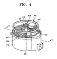
- FIG. 4 is a perspective view of a dust compression plate and ascending/descending units to move the dust compression plate up and down, which are mounted in a dust collecting apparatus according to an exemplary embodiment of the present disclosure
- FIG. 5 is a sectional view taken along line VI-VI in FIG. 4 ;
- FIG. 6 is a sectional view showing a situation in which the dust compression plate of FIG. 5 is lowered so as to compress dust in a dust collecting case;
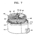
- FIG. 7 is a perspective view of a filter unit mounted in a dust collecting apparatus according to an exemplary embodiment of the present disclosure.
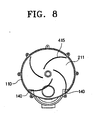
- FIG. 8 is a plane view of a wiper disposed in a dust collecting apparatus according to an exemplary embodiment of the present disclosure.
- a dust collecting apparatus according to an exemplary embodiment of the present disclosure comprises a dust collecting unit 100, a filter unit 200, a dust compression plate 300, a rotating unit 400 and a top cover 500.
- a dust collecting unit 100 a dust collecting unit 100
- a filter unit 200 a dust compression plate 300
- a rotating unit 400 a rotating unit 400
- a top cover 500 a dust collecting unit 100
- the elements 100, 200, 300, 400 and 500 will be described in detail with reference to FIGS. 2 and 3 .
- the dust collecting unit 100 comprises a dust collecting case 110, and a cyclone chamber 120, a dust collecting chamber 130 and a fine dust collecting chamber 140 which are spaced apart from each other within the dust collecting case 110. Additionally, the dust collecting unit 100 comprises an inlet 150 which fluidly communicates with the cyclone chamber 120.
- the dust collecting case 110 has a substantially cylindrical shape having an open upper end and a closed lower end.
- a plurality of first fixing units 111 protrude at regular intervals along an outside surface of the upper end of the dust collecting case 110 in order to fix the filter unit 200 disposed above the dust collecting case 110.
- the cyclone chamber 120 includes a spiral guide 121 which extends a predetermined distance upwards from an area adjacent to the inlet 150.
- the spiral guide 121 makes drawn-in air and dust flowing through the inlet 150 rotate, so as to effectively separate the drawn-in air from dust in an upper part of the cyclone chamber 120 using a centrifugal force.
- a blocking plate 128 and a dust discharge space 125 are formed by cutting a portion of an upper side of a first partition 123 which divides the dust collecting case 110 into the cyclone chamber 120 and the dust collecting chamber 130.
- a vertical pipe 126 to support the spiral guide 121 is disposed at substantially the center of the cyclone chamber 120.
- a cylindrical grill filter 127 to guide air separated from dust in the cyclone chamber 120 toward the filter unit 200 is disposed at an upper end of the vertical pipe 126.
- the blocking plate 128 disposed along an outside surface of an upper end of the cylindrical grill filter 127 seals an upper part of the cyclone chamber 120.
- the blocking plate 128 is supported by a mounting ring 129 fitting into a jaw 113 inside the upper end of the dust collecting case 110.
- the dust collecting chamber 130 is disposed adjacent to the cyclone chamber 120.
- the fine dust collecting chamber 140 is disposed adjacent to both sides of the cyclone chamber 120, and is partitioned from the collecting chamber 130 by a second partition 141.
- the filter unit 200 comprises a filter case 210, a filter supporter 220 and a filter 230.
- the filter case 210 has an open upper part and a floor 211 for closing the upper part of the dust collecting chamber 130.
- a first through hole 211 a through which a threaded rod 310 disposed on a pressing plate 300 penetrates is disposed at substantially the center of the floor 211.
- a communicating hole 211 b into which air discharged from the grill filter 127 flows is disposed in a position corresponding to the grill filter 127.
- a fine dust exhaust outlet 211 c is disposed in a position corresponding to the fine dust collecting chamber 140 in order to discharge fine dust particles on the floor 211 to the fine dust collecting chamber 140.
- a plurality of second fixing units 213 which are aligned with the first fixing units 111 protrude along an outside surface of the filter case 210.
- the second fixing units 213 comprise upper mounting projections 213a and lower mounting projections 213b which are respectively disposed on upper and lower sides of the second fixing units 213.
- the upper mounting projections 213a detachably fit into a plurality of third fixing units 540 of the top cover 500, and the lower mounting projections 213b detachably fit into the first fixing units 111 of the dust collecting case 110.
- a plurality of grooves 215 are disposed at regular intervals along an inside surface of an upper end of the filter case 210, so that a plurality of fixing projections 221 of the filter supporter 220 can be inserted into the plurality of grooves 215.
- the filter supporter 220 has a substantially ring-like shape, and is inserted into the filter case 210 by the plurality of fixing projections 221 disposed on an outside surface of the filter supporter 220.
- the filter supporter 220 includes a first boss 223 and a plurality of first support ribs 225.
- the first boss 223 is disposed at substantially the center of the filter supporter 220 and is spaced apart from an inside surface of the filter supporter 220 by the plurality of first support ribs 225 at a predetermined distance.
- a second through hole 223a through which a supporting pipe 417 penetrates is disposed at substantially the center of the first boss 223.
- first support pieces 227 are disposed around an outside surface of the first boss 223 at regular intervals along the axis of the first boss 223.
- second support pieces 229 are disposed around an inside surface of the filter supporter 220 at regular intervals along the axis of the filter supporter 220.
- the filter 230 is folded in an accordion-like manner and has a substantially circular shape so as to be inserted into the filter supporter 220.
- the inside 231 and the outside 233 of the filter 230 are mounted by the plurality of first and second support pieces 227 and 229, respectively, and accordingly the filter 230 may be fixed inside the filter supporter 220 without rotation, and may be simultaneously supported by the first support ribs 225 when being mounted.
- the filter 230 functions to filter fine dust particles contained in air flowing into the filter case 210 through the communicating hole 211 b.
- the dust compression plate 300 has dimensions equal to or less than sectional dimensions of the dust collecting chamber 130, and is disposed in the dust collecting chamber 130 so as to move upwardly and downwardly in the dust collecting chamber 130.
- An initial position (referring to FIG. 5 ) of the dust compression plate 300 is at the top of the dust collecting chamber 130, in order not to interfere with the movement of dust flowing from the cyclone chamber 120 to the dust collecting chamber 130 through the dust discharge space 125.
- the dust compression plate 300 includes the threaded rod 310 which extends upwards for a predetermined length from a top surface of the dust compression plate 300, and the dust compression plate 300 is moved up or down inside the dust collecting chamber 130 by power transferred from the rotating unit 400 through the threaded rod 310.
- a seal ring 320 is coupled to a portion of the threaded rod 310 in contact with the dust compression plate 300, and accordingly the seal ring 320 may seal off the first through hole 211 a through which the threaded rod 310 penetrates when the dust compression plate 300 has ascended, and may prevent dust collected in the dust collecting chamber 130 from flowing into the dust collecting case 210.
- the rotating unit 400 comprises a first rotating member 410, a second rotating member 420, a drive gear 430 and a motor 440.
- the first rotating member 410 is rotatably disposed between a lower side of the filter supporter 220 and the floor 211 of the filter case 210.
- the first rotating member 410 includes a second boss 411, and a plurality of second support ribs 413, which have a predetermined curvature and connect the second boss 411 to an inside surface of the first rotating member 410.
- the second support ribs 413 include a plurality of mounting grooves 414 disposed at the bottom surface thereof, into which each wiper 415 is fitted.
- the wipers 415 have an arcuate form, and the lower ends of the wipers 415 are in close contact with the floor 211. Accordingly, the wipers 415 may sweep fine dust particles deposited on the floor 211 while moving over the floor 211 following the rotation of the first rotating member 410, and may push the fine dust particles into the fine dust exhaust outlet 211 c.
- the supporting pipe 417 is disposed on a top surface of the second boss 411 and rotatably penetrates through the second through hole 223a of the first boss 223.
- the supporting pipe 417 includes a screw hole 417a in which a threaded portion complementary to the threaded rod 310 is formed, so that the threaded rod 310 can be screwed into the screw hole 417a. Accordingly, if the first rotating member 410 rotates clockwise and counterclockwise, the threaded rod 310 may raise and lower the dust compression plate 300 inside the dust collecting chamber 130 while moving upwardly and downwardly along the screw hole 417a.
- the second rotating member 420 is rotatably disposed between a bottom cover 500 and an upper side of the dust collecting case 220.
- the second rotating member 420 includes a third boss 421 disposed at substantially the center thereof, and a plurality of third support ribs 423.
- the supporting pipe 417 of the first rotating member 410 penetrates the third boss 421 to be coupled to the third boss 421, and the plurality of third support ribs 423 connect the third boss 421 to an inside surface of the second rotating member 420.
- strike tabs 425 having sufficient thickness to be partially inserted a predetermined distance into upper folded portions of the filter 230 are coupled to bottom surfaces of the third support ribs 423.
- the strike tabs 425 strike the upper side of the filter 230 while being repeatedly inserted into and removed from the gaps between the upper folded portions of the filter 230, so as to sweep fine dust particles attached to the filter 230 downward onto the floor 211 of the filter case 210.
- the strike tabs 425 may be formed of a soft material.
- a third through hole 421 a is formed in the third boss 421 of the second rotating member 420 and has a polygonal shape, for example, a hexagonal shape. This is so the third through hole 421 a can engage with a hexagonal mounting part 417b in a portion of the supporting pipe 417 which is inserted into the third through hole 421 a, to transfer a rotation force exerted by the second rotating member 420 to the first rotating member 410. Accordingly, fine dust particles may be separated from the filter 230 using the strike tabs 425 by simultaneously rotating the first and second rotating members 410 and 420, and the separated dust particles may be deposited on the floor 211 and at the same time may be discharged to the fine dust collecting chamber 140 using the wipers 415.
- the second rotating member 420 includes a differential gear 427 disposed on a top surface of the third boss 421.
- the differential gear 427 is meshed with the drive gear 430, so that the second rotating member 420 can rotate using power transferred from the drive gear 430.
- a drive shaft 441 of the motor 440 is coupled to the center of the drive gear 430 through an opening 511 of the top cover 500 in order to transfer power exerted by the motor 440 to the differential gear 427.
- the motor 440 is disposed in such a manner as to fit into an accommodating part 510 of the top cover 500 and to be separated from the filter unit 200 and the outside of the dust collecting apparatus by a housing part 521 disposed on one side of a grip 520.
- This arrangement prevents unfiltered fine dust particles in air passing through the filter 230 or dust in air outside the dust collecting apparatus from flowing into the motor 440 as much as possible, and accordingly it is possible to protect the motor 440.
- the driving direction of the motor 440 may be reversed. For example, if the motor 440 is driven in one direction to lower the dust compression plate 300 using the second rotating member 420 until it is impossible for the dust compression plate 300 to compress dust any more, a predetermined load arises in the motor 440. In this situation, in order to protect the motor 440, the driving direction of the motor 440 may be reversed so that the dust compression plate 300 can be raised.
- the top cover 500 closes the upper part of the filter unit 200, and simultaneously discharges air discharged from the filter unit 200 through an exhaust outlet 530 disposed on one side of the top cover 500 to the outside of the dust collecting apparatus.
- the top cover 500 includes the plurality of third fixing units 540 disposed along the outside surface thereof in a position corresponding to the second fixing units 213 of the filter case 210. Additionally, an insertion opening 501 is disposed at substantially the center of the top cover 500 in order to receive an upper end of the threaded rod 310 when the dust compression plate 300 is raised and returned to the initial position (referring to FIG. 5 ).
- the grip 520 is disposed on an upper side of the top cover 500 so that the dust collecting apparatus can be easily separated from the main body (not shown) of the vacuum cleaner.
- the dust compression plate 300 is usually positioned above the dust discharge space 125 in order not to cover the dust discharge space 125. Dust flowing into the cyclone chamber 120 through the inlet 150 along with drawn-in air is separated from the drawn-in air using the centrifugal force, and the separated dust enters and is collected in the dust collecting chamber 130 through the dust discharge space 125. If a predetermined amount of dust D is deposited on the dust collecting chamber 130 as shown in FIG. 5 , a user may drive the motor 440 through a predetermined operation switch (not shown) mounted in a handle part (not shown) or in the main body (not shown) of the vacuum cleaner after operation of the vacuum cleaner has been halted.
- a predetermined operation switch not shown
- the drive gear 430 is rotated in one direction by the motor 400 to drive the differential gear 427 meshed with the drive gear 430.
- the second rotating member 420 is rotated in one direction by the differential gear 427, and the first rotating member 410 together with the second rotating member 420 is also rotated by power transferred through the supporting pipe 417.
- dust compression plate 300 While the threaded rod 310 screwed into the supporting pipe 417 of the first rotating member 410 being rotated in one direction is being moved down along the supporting pipe 417, the dust compression plate 300 is lowered inside the dust collecting chamber 130, as shown in FIG. 6 . Accordingly, dust D collected in the dust collecting chamber 130 may be compressed increasingly by lowering the dust compression plate 300, and a predetermined space to collect a significant amount of dust may be defined in the dust collecting chamber 130.
- the motor 440 may be driven in a direction opposite the original direction, and the first and second rotating members 410 and 420 may be rotated in reverse, and the drive gear 430 and differential gear 427 may be rotated in reverse, in a reverse manner to the situation of lowering the dust compression plate 300 described above.
- the dust compression plate 300 is raised inside the dust collecting chamber 130 so as to be returned to the initial position, as shown in FIG. 5 .
- a limit switch (not shown) or a hole sensor (not shown) may be mounted in predetermined positions on upper and lower inner walls of the dust collecting chamber 130, respectively, so that the raised and lowered positions of the dust compression plate 300 can be detected and the driving direction of the motor 440 can be reversed.
- the dust collecting apparatus may clean the filter while compressing dust, as described above. Such a process of cleaning a filter is now described with reference to FIGS. 7 and 8 .
- Power is transferred in the order of the drive gear 430, differential gear 427 and first and second rotating members 410 and 420 according to the driving direction of the motor 440, in the same manner as the process of compressing dust described above, so detailed description thereof is omitted.
- the plurality of strike tabs 425 may strike the upper side of the filter 230 while being repeatedly inserted into and removed from the gaps between the upper folded portions of the filter 230. Accordingly, fine dust particles attached to the filter 230 may be removed from the filter 230 to allow the fine dust particles to descend onto the floor 211 of the filter case 210 to be deposited thereon.
- the fine dust particles deposited on the floor 211 may be removed outwardly from the center of the floor 211 by the plurality of wipers 415 which rotate together with the first rotating member 410, as shown in FIG. 8 , and as a result, the fine dust particles may be discharged to the fine dust collecting chamber 140.
- the fine dust particles detached from the filter 230 are collected in the fine dust collecting chamber 140 by being removed from the floor 211, and thus it is possible to prevent the fine dust particles flowing into the connecting hole 211 b of the floor 211 together with air from being reattached to the filter 230 during vacuum cleaning.
- the dust compression plate is raised and lowered using power transferred from the motor to compress dust and simultaneously to remove dust attached to the filter from the filter, so there is no need for a user to clean a filter separately.
- a filter may be maintained in a clean condition, and thus the efficiency of the filter in fine dust particles can increase and it is possible to prevent a suction force used to draw in dust from a surface to be cleaned from being reduced due to an increase in pressure inside the dust collecting apparatus.
- each power source for dust compression and filter cleaning is not required separately, and thus the number of units is reduced to reduce manufacturing costs. Additionally, a compact dust collecting apparatus can be maintained.
Landscapes
- Engineering & Computer Science (AREA)
- Mechanical Engineering (AREA)
- Filters For Electric Vacuum Cleaners (AREA)
- Filtering Of Dispersed Particles In Gases (AREA)
Claims (10)
- Appareil de collecte de la poussière pour un aspirateur, comprenant :une unité de collecte de la poussière (100) montée de manière amovible dans un corps principal de l'aspirateur, l'unité de collecte de la poussière (100) étant configurée pour séparer et collecter la poussière provenant de l'air aspiré circulant dans celle-ci,une unité de filtration (200) disposée au-dessus de l'unité de collecte de la poussière (100), l'unité de filtration (200) comprenant un filtre (230) destiné à filtrer les particules de poussière fine contenues dans l'air à partir duquel la poussière a été séparée par l'unité de collecte de la poussière (100),un capot supérieur (500) destiné à couvrir l'unité de filtration (200) et à évacuer l'air filtré à travers le filtre (230),une unité rotative (400) disposée à l'intérieur de l'unité de filtration (200), l'unité rotative (400) étant configurée pour percuter une partie du filtre (230) et pour retirer les particules de poussière fine fixées sur le filtre, etune plaque de compression de la poussière (300) destinée à comprimer la poussière collectée en étant déplacée vers le haut et vers le bas à l'intérieur de l'unité de collecte de la poussière (100) par de l'énergie transférée depuis l'unité rotative (400).
- Appareil de collecte de la poussière selon la revendication 1, dans lequel l'unité rotative (400) comprend :un moteur (440) qui est disposé sur le capot supérieur (500) de manière à être séparé par rapport à l'unité de filtration (200),un premier élément rotatif (410) qui est disposé avec possibilité de rotation en dessous du filtre (230),un deuxième élément rotatif (420) disposé avec possibilité de rotation au-dessus du filtre (230) qui reçoit de l'énergie du moteur (440), le deuxième élément rotatif (420) étant configuré pour tourner dans le même sens que le premier élément rotatif (410) en transférant de l'énergie au premier élément rotatif,un ou plusieurs éléments percutants (425) fixés sur le deuxième élément rotatif (420), les un ou plusieurs éléments percutants (425) étant configurés pour percuter le filtre (230) à la suite de la rotation du deuxième élément rotatif (420) alors qu'il est en contact avec le filtre (230), etun ou plusieurs balais (415) qui sont couplés au premier élément rotatif (410) pour évacuer vers l'unité de collecte de la poussière (100) la poussière, qui est retirée du filtre (230) par les un ou plusieurs éléments percutants (425) et déposée sur un plancher de l'unité de collecte de la poussière (100).
- Appareil de collecte de la poussière selon la revendication 2, comprenant en outre :une chambre à cyclone (120) destinée à séparer la poussière circulant dans la chambre de collecte de la poussière (130) par rapport à l'air en utilisant une force centrifuge,une chambre de collecte de la poussière (130) destinée à collecter la poussière séparée par la chambre à cyclone (120), la chambre de collecte de la poussière (130) étant éloignée par rapport à la chambre à cyclone (120), etune ou plusieurs chambres de collecte de poussière fine (140) destinées à collecter des particules de poussière fine évacuées à partir de l'unité de filtration (200), les une ou plusieurs chambres de collecte de poussière fine étant éloignées par rapport à la chambre à cyclone et à la chambre de collecte de la poussière, respectivement.
- Appareil de collecte de la poussière selon la revendication 2 ou 3, dans lequel le filtre (230) est monté de manière fixe à l'intérieur de l'unité de collecte de la poussière (100), est plié à la manière d'un accordéon et présente une forme globalement circulaire, et
dans lequel les un ou plusieurs éléments percutants (425) ont une épaisseur suffisante pour être partiellement insérés dans des parties pliées supérieures du filtre (230). - Appareil de collecte de la poussière selon l'une quelconque des revendications 2 à 4, dans lequel les un ou plusieurs balais (415) ont une forme courbe.
- Appareil de collecte de la poussière selon l'une quelconque des revendications 2 à 5, dans lequel le premier élément rotatif (410) comprend de manière intégrée un tube de support (417), qui pénètre dans le filtre (230) et est connecté au deuxième élément rotatif (420).
- Appareil de collecte de la poussière selon la revendication 6, dans lequel la plaque de compression de la poussière (300) comprend de manière intégrée une tige filetée (310) qui est vissée dans un trou de vis (417a) du tube de support (417), et
dans lequel la plaque de compression de la poussière (300) est déplacée vers le haut et vers le bas à l'intérieur de la chambre de collecte de la poussière (130), selon le mouvement de la tige filetée (310) le long du tube de support (417) au moyen du tube de support dans lequel la tige filetée est entraînée en rotation dans le sens des aiguilles d'une montre et dans le sens inverse des aiguilles d'une montre en contact avec le premier élément rotatif (410). - Appareil de collecte de la poussière selon l'une quelconque des revendications 2 à 7, dans lequel le moteur (440) a un sens de rotation qui s'inverse en raison d'une charge se produisant dans le moteur, et dans lequel la charge est provoquée par la descente de la plaque de compression de la poussière (300) qui est déplacée vers le bas par la rotation des premier et deuxième éléments rotatifs (410, 420) dans un sens qui est gêné par le fait que la poussière est complètement comprimée.
- Appareil de collecte de la poussière selon l'une quelconque des revendications 3 à 7, dans lequel le moteur (440) a un sens de rotation qui change en fonction du fait que la plaque de compression de la poussière (300) est soulevée ou abaissée, ce qui est détecté par une paire d'interrupteurs de fin de course ou une paire de capteurs à trou montés à des positions prédéterminées sur les parois intérieures supérieures et inférieures de la chambre de collecte de la poussière (130), respectivement.
- Appareil de collecte de la poussière selon les revendications 2 à 9, dans lequel les un ou plusieurs éléments percutants (425) sont constitués de matériaux mous de manière à empêcher que le filtre (230) ne soit endommagé lorsque le filtre est percuté.
Applications Claiming Priority (2)
| Application Number | Priority Date | Filing Date | Title |
|---|---|---|---|
| US92683207P | 2007-04-30 | 2007-04-30 | |
| KR1020070059481A KR20080097104A (ko) | 2007-04-30 | 2007-06-18 | 진공청소기용 집진장치 |
Publications (3)
| Publication Number | Publication Date |
|---|---|
| EP1987753A2 EP1987753A2 (fr) | 2008-11-05 |
| EP1987753A3 EP1987753A3 (fr) | 2012-07-11 |
| EP1987753B1 true EP1987753B1 (fr) | 2014-12-17 |
Family
ID=39666242
Family Applications (1)
| Application Number | Title | Priority Date | Filing Date |
|---|---|---|---|
| EP07025014.7A Expired - Fee Related EP1987753B1 (fr) | 2007-04-30 | 2007-12-21 | Appareil de collecte de poussière pour aspirateur |
Country Status (4)
| Country | Link |
|---|---|
| US (1) | US7785381B2 (fr) |
| EP (1) | EP1987753B1 (fr) |
| AU (1) | AU2008200168B2 (fr) |
| CA (1) | CA2618070C (fr) |
Families Citing this family (56)
| Publication number | Priority date | Publication date | Assignee | Title |
|---|---|---|---|---|
| US8978197B2 (en) * | 2009-03-13 | 2015-03-17 | Lg Electronics Inc. | Vacuum cleaner |
| US8404034B2 (en) | 2005-12-10 | 2013-03-26 | Lg Electronics Inc. | Vacuum cleaner and method of controlling the same |
| US8012250B2 (en) | 2005-12-10 | 2011-09-06 | Lg Electronics Inc. | Vacuum cleaner |
| US7882592B2 (en) * | 2005-12-10 | 2011-02-08 | Lg Electronics Inc. | Vacuum cleaner |
| US8281455B2 (en) * | 2005-12-10 | 2012-10-09 | Lg Electronics Inc. | Vacuum cleaner |
| US8544143B2 (en) * | 2005-12-10 | 2013-10-01 | Lg Electronics Inc. | Vacuum cleaner with removable dust collector, and methods of operating the same |
| US7987551B2 (en) * | 2005-12-10 | 2011-08-02 | Lg Electronics Inc. | Vacuum cleaner |
| US7749295B2 (en) * | 2005-12-10 | 2010-07-06 | Lg Electronics Inc. | Vacuum cleaner with removable dust collector, and methods of operating the same |
| GB2436308A (en) * | 2006-03-23 | 2007-09-26 | Adrian Christopher Arnold | Particle separator |
| EP1949842B1 (fr) | 2007-01-24 | 2015-03-04 | LG Electronics Inc. | Aspirateur |
| US7854782B2 (en) * | 2007-04-30 | 2010-12-21 | Samsung Gwangju Electronics Co., Ltd. | Vacuum cleaner |
| GB2455535A (en) * | 2007-12-12 | 2009-06-17 | Prime Sourcing Ltd | Cyclone chamber with vortex shield |
| US20090165240A1 (en) * | 2007-12-27 | 2009-07-02 | Daewoo Electronics Corporation | Vacuum cleaner |
| US8528163B2 (en) * | 2009-02-12 | 2013-09-10 | Lg Electronics Inc. | Vacuum cleaner |
| US8151409B2 (en) * | 2009-02-26 | 2012-04-10 | Lg Electronics Inc. | Vacuum cleaner |
| US8713752B2 (en) * | 2009-03-13 | 2014-05-06 | Lg Electronics Inc. | Vacuum cleaner |
| KR101566312B1 (ko) * | 2009-05-11 | 2015-11-06 | 삼성전자주식회사 | 제진장치를 구비한 진공청소기 |
| DE202009007484U1 (de) * | 2009-05-26 | 2010-10-14 | Smg Sportplatzmaschinenbau Gmbh | Fahrbare Vorrichtung zum Abtragen von Füllgut von einer Fläche |
| US8128719B1 (en) | 2009-08-21 | 2012-03-06 | Cummins Filtration Ip Inc. | Filter element with percussion band |
| EP2422672B1 (fr) * | 2009-08-24 | 2015-10-21 | LG Electronics Inc. | Aspirateur |
| US8393050B2 (en) * | 2009-10-28 | 2013-03-12 | Robert M. Witter | Portable cyclonic dust collector/vacuum cleaner |
| US8152877B2 (en) * | 2010-03-12 | 2012-04-10 | Euro-Pro Operating Llc | Shroud for a cleaning service apparatus |
| JP4866477B1 (ja) * | 2010-09-01 | 2012-02-01 | シャープ株式会社 | 電気掃除機 |
| WO2012113414A1 (fr) * | 2011-02-22 | 2012-08-30 | Aktiebolaget Electrolux | Aspirateur |
| CN105072965A (zh) * | 2013-02-28 | 2015-11-18 | 奥马克罗知识产权有限公司 | 表面清洁装置 |
| US20140237768A1 (en) | 2013-02-28 | 2014-08-28 | G.B.D. Corp. | Surface cleaning apparatus |
| US9204773B2 (en) | 2013-03-01 | 2015-12-08 | Omachron Intellectual Property Inc. | Surface cleaning apparatus |
| CN203341657U (zh) * | 2013-04-11 | 2013-12-18 | 江苏美的春花电器股份有限公司 | 吸尘器及其集尘装置 |
| KR101411685B1 (ko) * | 2013-04-18 | 2014-07-02 | 엘지전자 주식회사 | 진공 청소기 |
| US10631697B2 (en) | 2014-02-14 | 2020-04-28 | Techtronic Industries Co. Ltd. | Separator configuration |
| US9980620B2 (en) | 2014-03-12 | 2018-05-29 | Aktiebolaget Electrolux | Bagless vacuum cleaner with filter cleaning member |
| AU2014391045B2 (en) * | 2014-04-14 | 2017-06-01 | Jiangsu Midea Cleaning Appliances Co., Ltd. | Cyclone separator |
| JP6109415B2 (ja) * | 2014-04-14 | 2017-04-05 | 江蘇美的清潔電器股▲分▼有限公司 | 掃除機用集塵装置 |
| CA2928112A1 (fr) | 2014-08-13 | 2016-02-18 | Jiangsu Midea Cleaning Appliances Co., Ltd. | Aspirateur et aspirateur vertical |
| EP3209175B1 (fr) | 2014-10-22 | 2023-01-04 | Techtronic Industries Co. Ltd. | Aspirateur à main |
| WO2016065148A2 (fr) | 2014-10-22 | 2016-04-28 | Techtronic Industries Co. Ltd. | Aspirateur doté d'un séparateur cyclonique |
| WO2016065146A1 (fr) | 2014-10-22 | 2016-04-28 | Techtronic Industries Co. Ltd. | Aspirateur doté d'un séparateur cyclonique |
| KR101641261B1 (ko) | 2014-10-28 | 2016-07-20 | 엘지전자 주식회사 | 청소기 |
| KR102308501B1 (ko) | 2015-03-27 | 2021-10-06 | 삼성전자주식회사 | 사이클론 집진장치 및 이를 포함하는 진공 청소기 |
| EP3163203B1 (fr) * | 2015-10-30 | 2020-12-02 | LG Electronics Inc. | Rafraîchisseur d'air |
| TWI760214B (zh) | 2016-03-31 | 2022-04-01 | 南韓商Lg電子股份有限公司 | 吸塵器 |
| WO2017171500A1 (fr) | 2016-03-31 | 2017-10-05 | 엘지전자 주식회사 | Appareil de nettoyage |
| US10638903B2 (en) | 2016-03-31 | 2020-05-05 | Lg Electronics Inc. | Cleaner |
| TWI732845B (zh) * | 2016-03-31 | 2021-07-11 | 南韓商Lg電子股份有限公司 | 吸塵器 |
| EP3323334B1 (fr) | 2016-11-17 | 2019-06-05 | Black & Decker Inc. | Aspirateur |
| KR102000611B1 (ko) * | 2017-07-12 | 2019-07-16 | 엘지전자 주식회사 | 진공 청소기 |
| KR102141111B1 (ko) * | 2018-05-24 | 2020-08-04 | 이춘우 | 복수개의 터닝 포켓을 포함하는 포집부에 구비된 필터청소수단 |
| KR102021922B1 (ko) | 2018-02-20 | 2019-09-17 | 엘지전자 주식회사 | 청소기 |
| KR102070065B1 (ko) * | 2018-03-14 | 2020-03-02 | 엘지전자 주식회사 | 싸이클론 집진 장치 및 이를 포함하는 청소기 |
| US11930987B2 (en) | 2018-04-20 | 2024-03-19 | Omachron Intellectual Property Inc. | Surface cleaning apparatus |
| CN114072032B (zh) | 2019-05-01 | 2023-04-14 | 尚科宁家运营有限公司 | 真空清洁器以及与真空清洁器一起使用的对接站 |
| KR102746010B1 (ko) * | 2019-06-07 | 2024-12-24 | 엘지전자 주식회사 | 청소기 |
| US11547257B2 (en) | 2020-02-04 | 2023-01-10 | Dustless Depot, Llc | Vacuum bag with inlet gasket and closure seal |
| WO2024055224A1 (fr) | 2022-09-15 | 2024-03-21 | Sharkninja Operating Llc | Aspirateur et station d'accueil configurée pour l'interaction avec celui-ci |
| USD1077390S1 (en) * | 2023-08-11 | 2025-05-27 | Suzhou Inotek Intelligent Technology Co., Ltd | Vacuum cleaner |
| USD1097399S1 (en) * | 2023-10-24 | 2025-10-07 | Oneida Air Systems, Inc. | Dust collection bucket |
Family Cites Families (42)
| Publication number | Priority date | Publication date | Assignee | Title |
|---|---|---|---|---|
| US1038167A (en) * | 1910-12-14 | 1912-09-10 | George Maitland | Vacuum-cleaner. |
| US1345478A (en) * | 1919-03-31 | 1920-07-06 | Elza T S Cliffe | Vacuum cleaning apparatus |
| US2283836A (en) * | 1940-12-07 | 1942-05-19 | Hoover Co | Suction cleaner |
| US2594456A (en) * | 1948-10-16 | 1952-04-29 | Hoover Co | Vacuum cleaner |
| US3621640A (en) * | 1968-10-14 | 1971-11-23 | Matsushita Electric Industrial Co Ltd | Electric vacuum cleaner |
| DE1964261C3 (de) * | 1969-12-22 | 1973-06-28 | Matsushita Electric Ind Co Ltd | Elektromotorisch angetriebener Staubsauger |
| US3708962A (en) * | 1970-03-20 | 1973-01-09 | Sanyo Electric Co | Vacuum cleaner |
| JPS544854Y2 (fr) * | 1972-09-05 | 1979-03-01 | ||
| US3856488A (en) * | 1972-09-05 | 1974-12-24 | Mitsubishi Electric Corp | Electric vacuum cleaner |
| JPS5485560A (en) | 1977-12-20 | 1979-07-07 | Tokyo Electric Co Ltd | Electric cleaner |
| JPS5499355A (en) * | 1978-01-20 | 1979-08-06 | Tokyo Electric Co Ltd | Electric cleaner |
| JPS6047844B2 (ja) * | 1978-01-31 | 1985-10-24 | 東芝テック株式会社 | 電気掃除機 |
| US4533371A (en) * | 1982-04-25 | 1985-08-06 | Kabushiki Kaisha Suiden | Vacuum cleaner |
| US4557738A (en) * | 1982-05-26 | 1985-12-10 | Menasian David R | Vacuum collector |
| DE3242929A1 (de) * | 1982-11-20 | 1984-05-24 | Vorwerk & Co Interholding Gmbh, 5600 Wuppertal | Filtereinrichtung, insbesondere fuer staubsauger |
| US4592764A (en) * | 1983-06-30 | 1986-06-03 | Sharp Kabushiki Kaisha | Vacuum cleaner |
| US6070291A (en) * | 1998-01-09 | 2000-06-06 | Royal Appliance Mfg. Co. | Upright vacuum cleaner with cyclonic air flow |
| JP3530436B2 (ja) * | 1999-01-29 | 2004-05-24 | 三洋電機株式会社 | 掃除機用集塵装置及びアップライト型掃除機 |
| US6596044B1 (en) * | 2000-03-06 | 2003-07-22 | The Hoover Company | Dirt collecting system for a vacuum cleaner |
| JP3626413B2 (ja) * | 2000-08-19 | 2005-03-09 | エルジー電子株式会社 | 集塵装置及びこれを用いる真空掃除機 |
| WO2002038025A1 (fr) * | 2000-11-13 | 2002-05-16 | Matsushita Electric Corporation Of America | Aspirateur cyclonique equipe d'un filtre et d'une brosse filtre |
| SE518257C2 (sv) * | 2001-01-11 | 2002-09-17 | Electrolux Ab | Anordning vid en dammsugare |
| US6598263B2 (en) * | 2001-05-09 | 2003-07-29 | The Hoover Company | Vacuum cleaner dirt collecting system with filter cleaning devices |
| EP1283021B1 (fr) * | 2001-08-08 | 2010-09-22 | Panasonic Corporation | Aspirateur comprenant des moyens pour comprimer la poussière |
| JP3699679B2 (ja) * | 2001-12-28 | 2005-09-28 | 松下電器産業株式会社 | 電気掃除機 |
| KR100445802B1 (ko) * | 2002-02-28 | 2004-08-25 | 삼성광주전자 주식회사 | 진공청소기용 사이클론 집진장치 |
| KR100445808B1 (ko) * | 2002-02-28 | 2004-08-25 | 삼성광주전자 주식회사 | 진공청소기용 사이클론 집진장치 |
| KR100445806B1 (ko) * | 2002-02-28 | 2004-08-25 | 삼성광주전자 주식회사 | 진공청소기용 사이클론 집진장치 |
| KR100433414B1 (ko) * | 2002-05-11 | 2004-05-31 | 삼성광주전자 주식회사 | 진공청소기용 사이클론 집진장치 |
| CN1268277C (zh) * | 2002-11-28 | 2006-08-09 | 松下电器产业株式会社 | 电动吸尘器 |
| ITMO20030012A1 (it) * | 2003-01-24 | 2004-07-25 | Soteco S P A | Aspirapolvere perfezionato. |
| KR100485715B1 (ko) * | 2003-02-26 | 2005-04-28 | 삼성광주전자 주식회사 | 사이클론 진공 청소기의 집진장치 |
| KR100518804B1 (ko) * | 2003-03-31 | 2005-10-06 | 삼성광주전자 주식회사 | 사이클론집진장치의 필터청소기구 |
| KR100485699B1 (ko) * | 2003-04-14 | 2005-04-28 | 삼성광주전자 주식회사 | 진공청소기의 사이클론집진장치용 필터조립체 |
| US7351269B2 (en) * | 2003-12-22 | 2008-04-01 | Lau Kwok Yau | Self cleaning filter and vacuum incorporating same |
| CN100512740C (zh) * | 2004-04-07 | 2009-07-15 | 东芝泰格株式会社 | 电动吸尘器 |
| KR100869000B1 (ko) * | 2004-12-14 | 2008-11-17 | 엘지전자 주식회사 | 진공청소기의 먼지압축방법 및 진공청소기의 먼지압축장치 |
| KR100634805B1 (ko) | 2005-03-07 | 2006-10-16 | 엘지전자 주식회사 | 청소기의 집진기 |
| JP2007020769A (ja) | 2005-07-14 | 2007-02-01 | Matsushita Electric Ind Co Ltd | 電気掃除機 |
| JP3999791B2 (ja) * | 2005-07-21 | 2007-10-31 | 株式会社東芝 | 電気掃除機 |
| US7749295B2 (en) * | 2005-12-10 | 2010-07-06 | Lg Electronics Inc. | Vacuum cleaner with removable dust collector, and methods of operating the same |
| US7611558B2 (en) * | 2007-04-30 | 2009-11-03 | Samsung Gwangju Electronics Co., Ltd. | Dust compressing apparatus of vacuum cleaner |
-
2007
- 2007-09-27 US US11/904,423 patent/US7785381B2/en not_active Expired - Fee Related
- 2007-12-21 EP EP07025014.7A patent/EP1987753B1/fr not_active Expired - Fee Related
-
2008
- 2008-01-11 AU AU2008200168A patent/AU2008200168B2/en not_active Ceased
- 2008-01-14 CA CA2618070A patent/CA2618070C/fr not_active Expired - Fee Related
Also Published As
| Publication number | Publication date |
|---|---|
| AU2008200168B2 (en) | 2009-12-10 |
| US20080264007A1 (en) | 2008-10-30 |
| EP1987753A2 (fr) | 2008-11-05 |
| EP1987753A3 (fr) | 2012-07-11 |
| AU2008200168A1 (en) | 2008-11-13 |
| CA2618070A1 (fr) | 2008-10-30 |
| US7785381B2 (en) | 2010-08-31 |
| CA2618070C (fr) | 2010-12-07 |
Similar Documents
| Publication | Publication Date | Title |
|---|---|---|
| CA2618070C (fr) | Collecteur de poussiere pour aspirateur | |
| JP3749173B2 (ja) | 掃除機用集塵装置及び電気掃除機 | |
| JP4084323B2 (ja) | 真空掃除機の集塵ユニット | |
| KR100623915B1 (ko) | 먼지 분리장치 | |
| KR100390608B1 (ko) | 진공청소기의 사이클론 집진장치 | |
| AU2007249112B2 (en) | A vacuum cleaner | |
| US7501002B2 (en) | Cyclone dust separator and a vacuum cleaner having the same | |
| CN102438497B (zh) | 具备除尘装置的真空吸尘器 | |
| KR100445470B1 (ko) | 진공청소기용 집진케이싱 및 그것을 구비하는 청소기 본체 | |
| AU2007200171B2 (en) | Vacuum cleaner filter cleaning mechanisms | |
| EP1776910B1 (fr) | Collecteur poussière à cyclones multiples pour aspirateur | |
| KR20080097104A (ko) | 진공청소기용 집진장치 | |
| AU2008203474A1 (en) | Cyclone dust-collecting apparatus for vacuum cleaner | |
| GB2385812A (en) | Grill cleaning member for cyclone dust cleaning apparatus | |
| CA2618091A1 (fr) | Collecteur de poussiere pour aspirateur | |
| KR100964699B1 (ko) | 진공 청소기의 집진장치 | |
| KR101306738B1 (ko) | 진공청소기 | |
| JP2005261963A (ja) | 掃除機用集塵装置及びアップライト型掃除機 | |
| KR100992221B1 (ko) | 진공 청소기 | |
| EP1776911A2 (fr) | Collecteur de poussière pour aspirateur | |
| KR20020034299A (ko) | 진공청소기의 사이클론 집진장치 | |
| EP1743558B1 (fr) | Appareil séparateur de poussière | |
| KR100582047B1 (ko) | 진공청소기용 집진케이싱 | |
| KR100846904B1 (ko) | 진공 청소기 | |
| KR101393491B1 (ko) | 먼지압축장치 및 이를 구비한 진공청소기 |
Legal Events
| Date | Code | Title | Description |
|---|---|---|---|
| PUAI | Public reference made under article 153(3) epc to a published international application that has entered the european phase |
Free format text: ORIGINAL CODE: 0009012 |
|
| AK | Designated contracting states |
Kind code of ref document: A2 Designated state(s): AT BE BG CH CY CZ DE DK EE ES FI FR GB GR HU IE IS IT LI LT LU LV MC MT NL PL PT RO SE SI SK TR |
|
| AX | Request for extension of the european patent |
Extension state: AL BA HR MK RS |
|
| RAP1 | Party data changed (applicant data changed or rights of an application transferred) |
Owner name: SAMSUNG ELECTRONICS CO., LTD. |
|
| PUAL | Search report despatched |
Free format text: ORIGINAL CODE: 0009013 |
|
| AK | Designated contracting states |
Kind code of ref document: A3 Designated state(s): AT BE BG CH CY CZ DE DK EE ES FI FR GB GR HU IE IS IT LI LT LU LV MC MT NL PL PT RO SE SI SK TR |
|
| AX | Request for extension of the european patent |
Extension state: AL BA HR MK RS |
|
| RIC1 | Information provided on ipc code assigned before grant |
Ipc: A47L 9/10 20060101AFI20120606BHEP Ipc: A47L 9/20 20060101ALI20120606BHEP |
|
| RAP1 | Party data changed (applicant data changed or rights of an application transferred) |
Owner name: SAMSUNG ELECTRONICS CO., LTD. |
|
| 17P | Request for examination filed |
Effective date: 20130111 |
|
| AKX | Designation fees paid |
Designated state(s): DE FR GB |
|
| GRAP | Despatch of communication of intention to grant a patent |
Free format text: ORIGINAL CODE: EPIDOSNIGR1 |
|
| RIC1 | Information provided on ipc code assigned before grant |
Ipc: A47L 9/10 20060101AFI20140624BHEP Ipc: A47L 9/20 20060101ALI20140624BHEP |
|
| INTG | Intention to grant announced |
Effective date: 20140707 |
|
| GRAS | Grant fee paid |
Free format text: ORIGINAL CODE: EPIDOSNIGR3 |
|
| GRAA | (expected) grant |
Free format text: ORIGINAL CODE: 0009210 |
|
| AK | Designated contracting states |
Kind code of ref document: B1 Designated state(s): DE FR GB |
|
| REG | Reference to a national code |
Ref country code: GB Ref legal event code: FG4D |
|
| REG | Reference to a national code |
Ref country code: DE Ref legal event code: R096 Ref document number: 602007039674 Country of ref document: DE Effective date: 20150129 |
|
| PGFP | Annual fee paid to national office [announced via postgrant information from national office to epo] |
Ref country code: DE Payment date: 20141223 Year of fee payment: 8 |
|
| PGFP | Annual fee paid to national office [announced via postgrant information from national office to epo] |
Ref country code: FR Payment date: 20141222 Year of fee payment: 8 Ref country code: GB Payment date: 20150126 Year of fee payment: 8 |
|
| REG | Reference to a national code |
Ref country code: DE Ref legal event code: R097 Ref document number: 602007039674 Country of ref document: DE |
|
| PLBE | No opposition filed within time limit |
Free format text: ORIGINAL CODE: 0009261 |
|
| STAA | Information on the status of an ep patent application or granted ep patent |
Free format text: STATUS: NO OPPOSITION FILED WITHIN TIME LIMIT |
|
| 26N | No opposition filed |
Effective date: 20150918 |
|
| REG | Reference to a national code |
Ref country code: DE Ref legal event code: R119 Ref document number: 602007039674 Country of ref document: DE |
|
| GBPC | Gb: european patent ceased through non-payment of renewal fee |
Effective date: 20151221 |
|
| REG | Reference to a national code |
Ref country code: FR Ref legal event code: ST Effective date: 20160831 |
|
| PG25 | Lapsed in a contracting state [announced via postgrant information from national office to epo] |
Ref country code: DE Free format text: LAPSE BECAUSE OF NON-PAYMENT OF DUE FEES Effective date: 20160701 Ref country code: GB Free format text: LAPSE BECAUSE OF NON-PAYMENT OF DUE FEES Effective date: 20151221 |
|
| PG25 | Lapsed in a contracting state [announced via postgrant information from national office to epo] |
Ref country code: FR Free format text: LAPSE BECAUSE OF NON-PAYMENT OF DUE FEES Effective date: 20151231 |