EP1988231A1 - Dispositif d'auvent mobile - Google Patents
Dispositif d'auvent mobile Download PDFInfo
- Publication number
- EP1988231A1 EP1988231A1 EP06714503A EP06714503A EP1988231A1 EP 1988231 A1 EP1988231 A1 EP 1988231A1 EP 06714503 A EP06714503 A EP 06714503A EP 06714503 A EP06714503 A EP 06714503A EP 1988231 A1 EP1988231 A1 EP 1988231A1
- Authority
- EP
- European Patent Office
- Prior art keywords
- canvas
- attached
- projected corner
- roller supporting
- transverse guide
- Prior art date
- Legal status (The legal status is an assumption and is not a legal conclusion. Google has not performed a legal analysis and makes no representation as to the accuracy of the status listed.)
- Withdrawn
Links
- 238000004804 winding Methods 0.000 claims abstract description 296
- 208000018747 cerebellar ataxia with neuropathy and bilateral vestibular areflexia syndrome Diseases 0.000 claims description 66
- 238000003825 pressing Methods 0.000 description 34
- 238000000034 method Methods 0.000 description 28
- 230000008569 process Effects 0.000 description 28
- 238000003892 spreading Methods 0.000 description 19
- 230000007480 spreading Effects 0.000 description 19
- 230000001419 dependent effect Effects 0.000 description 8
- 230000007246 mechanism Effects 0.000 description 6
- 230000008859 change Effects 0.000 description 4
- 238000005452 bending Methods 0.000 description 3
- 230000001154 acute effect Effects 0.000 description 2
- 230000000694 effects Effects 0.000 description 2
- 239000004744 fabric Substances 0.000 description 2
- 230000002093 peripheral effect Effects 0.000 description 2
- 238000003860 storage Methods 0.000 description 2
- 229910000831 Steel Inorganic materials 0.000 description 1
- 230000008901 benefit Effects 0.000 description 1
- 238000005096 rolling process Methods 0.000 description 1
- 239000010959 steel Substances 0.000 description 1
- 229920003002 synthetic resin Polymers 0.000 description 1
- 239000000057 synthetic resin Substances 0.000 description 1
- XLYOFNOQVPJJNP-UHFFFAOYSA-N water Substances O XLYOFNOQVPJJNP-UHFFFAOYSA-N 0.000 description 1
Images


Classifications
-
- E—FIXED CONSTRUCTIONS
- E04—BUILDING
- E04F—FINISHING WORK ON BUILDINGS, e.g. STAIRS, FLOORS
- E04F10/00—Sunshades, e.g. Florentine blinds or jalousies; Outside screens; Awnings or baldachins
- E04F10/02—Sunshades, e.g. Florentine blinds or jalousies; Outside screens; Awnings or baldachins of flexible canopy materials, e.g. canvas ; Baldachins
- E04F10/06—Sunshades, e.g. Florentine blinds or jalousies; Outside screens; Awnings or baldachins of flexible canopy materials, e.g. canvas ; Baldachins comprising a roller-blind with means for holding the end away from a building
- E04F10/0611—Sunshades, e.g. Florentine blinds or jalousies; Outside screens; Awnings or baldachins of flexible canopy materials, e.g. canvas ; Baldachins comprising a roller-blind with means for holding the end away from a building with articulated arms supporting the movable end of the blind for deployment of the blind
- E04F10/0618—Sunshades, e.g. Florentine blinds or jalousies; Outside screens; Awnings or baldachins of flexible canopy materials, e.g. canvas ; Baldachins comprising a roller-blind with means for holding the end away from a building with articulated arms supporting the movable end of the blind for deployment of the blind whereby the pivot axis of the articulation is perpendicular to the roller
-
- E—FIXED CONSTRUCTIONS
- E04—BUILDING
- E04F—FINISHING WORK ON BUILDINGS, e.g. STAIRS, FLOORS
- E04F10/00—Sunshades, e.g. Florentine blinds or jalousies; Outside screens; Awnings or baldachins
- E04F10/02—Sunshades, e.g. Florentine blinds or jalousies; Outside screens; Awnings or baldachins of flexible canopy materials, e.g. canvas ; Baldachins
- E04F10/06—Sunshades, e.g. Florentine blinds or jalousies; Outside screens; Awnings or baldachins of flexible canopy materials, e.g. canvas ; Baldachins comprising a roller-blind with means for holding the end away from a building
- E04F10/0685—Covers or housings for the rolled-up blind
-
- E—FIXED CONSTRUCTIONS
- E04—BUILDING
- E04F—FINISHING WORK ON BUILDINGS, e.g. STAIRS, FLOORS
- E04F10/00—Sunshades, e.g. Florentine blinds or jalousies; Outside screens; Awnings or baldachins
- E04F10/02—Sunshades, e.g. Florentine blinds or jalousies; Outside screens; Awnings or baldachins of flexible canopy materials, e.g. canvas ; Baldachins
- E04F10/06—Sunshades, e.g. Florentine blinds or jalousies; Outside screens; Awnings or baldachins of flexible canopy materials, e.g. canvas ; Baldachins comprising a roller-blind with means for holding the end away from a building
- E04F10/0692—Front bars
-
- E—FIXED CONSTRUCTIONS
- E06—DOORS, WINDOWS, SHUTTERS, OR ROLLER BLINDS IN GENERAL; LADDERS
- E06B—FIXED OR MOVABLE CLOSURES FOR OPENINGS IN BUILDINGS, VEHICLES, FENCES OR LIKE ENCLOSURES IN GENERAL, e.g. DOORS, WINDOWS, BLINDS, GATES
- E06B9/00—Screening or protective devices for wall or similar openings, with or without operating or securing mechanisms; Closures of similar construction
- E06B9/24—Screens or other constructions affording protection against light, especially against sunshine; Similar screens for privacy or appearance; Slat blinds
- E06B2009/2482—Special shape
- E06B2009/2494—Trapezoidal or triangular
Definitions
- the present invention relates to a movable awning device having a structure for the front winding structure of a projected corner canvas which is used to cover a corner space portion of a projected corner portion of various buildings and the peripheral appearance of buildings in the vicinity of a projected corner so as to provide a good appearance.
- the present inventors have recently provided an awning device for a corner where a winding roller supported through bearings in a wall portion close to a corner in a projected corner portion of a building is formed of an inner roller and an outer roller which is engaged with and inserted on the inner roller in such a manner so as to be freely slidable, so that a corner canvas wound around the winding roller (hereinafter referred to as projected corner canvas) can be translated and pushed out diagonally forward to corner space portion while being unwound and spread or, conversely, a projected corner canvas that is projected into a corner space portion that can be drawn in parallel diagonally backward while being wound around a winding roller to store it, in order to cover the outside of the building including a corner space portion in a projected corner portion of the building (see following Patent Document 1).
- projected corner canvas a corner canvas wound around the winding roller
- a complex awning device which is complex, so that a projected corner portion of a building and a linear section in the vicinity thereof, a projected corner portion and a recessed corner portion, as well as the outside of the building, including one projected corner portion and another projected corner portion, can be covered with a projected corner canvas, a rectangular canvas and a recessed corner canvas or the like so that the appearance becomes better, is provided in the following Prior Art Application 2, which is currently not disclosed and known.
- a complex awning device where a number of canvases, including a projected corner canvas, are wound around a single winding roller in such a manner so as to overlap and unwind, and a spread projected corner canvas from among the number of canvases that is transversely slidable, is provided.
- a movable awning device where a projected corner canvas is freely and transversely slidable along a winding roller and the front bar of the projected corner canvas is movable in a parallel forward and backward direction by means of foldable arms, and the front bar of a projected corner canvas that is spread forward and transversely slidable, is provided.
- the awning devices disclosed in the following Patent Documents 2 to 4 are spread to the front when a front support frame is attached in the front end portion of the foldable arms which are freely foldable in two, a winding roller for a rectangular canvas is supported by the foldable arms through bearings, an attachment axis for supporting the rear end portion of the rectangular canvas is attached to a wall portion, and the rectangular canvas wound around the above described winding roller is unwound or, conversely, translated toward the wall portion so as to be stored in the wall when the spread rectangular canvas is wound around a winding roller and the foldable arms are folded in two as a whole.
- a movable awning device having a front winding structure for a rectangular canvas is disclosed.
- Patent Document 1 Prior Art Application 1
- Prior Art Applications 2 to 6 which relate to their own inventions at present, and recognize technological usefulness in the movable awning devices having a front winding structure as shown in Patent Documents 2 to 4.
- the focus of the present invention is to provide a single type and complex type movable awning devices which are novel and technically interesting for covering the outer periphery of a building including a corner space portion of a projected corner portion so as to provide a good appearance in the case where an awning device having a front winding structure is used as a base in the field.
- single types are referred to as single device or single awning device
- complex types are referred to as complex device or complex awning device.
- first invention and second invention Two inventions concerning single type movable awning devices S1a, S1b, S2a, S2b, S3a and S3b (hereinafter referred to as first invention and second invention) as well as the effects thereof are described in the following.
- the first invention is characterized in that (1) ... a roller supporting frame F1 is attached to the front end portion of foldable arms I1, I2, L1, L2, V1 and V2, winding rollers J1 to J3 for winding and unwinding a projected corner canvas G1 are supported by the roller supporting frame F1 through bearings, a slider 22 is attached to a transverse guide frame K1 provided on the wall side, and the top hem 1 of the above described projected corner canvas G1 is attached to the slider 22 (S1a, S1b, S2a, S2b, S3a, and S3b).
- the corner space portion in the projected corner portion N1 can be covered so as to provide a good appearance, or the canvas can be stored compactly without protruding from the projected corner portion N1 and with good appearance in the vicinity of the corner.
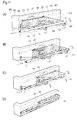
- Figs. 1 to 21 are views showing single type movable awning devices having a front winding structure and the related configurations according to the third embodiment.
- canvases are generally opaque, some canvases are shown in a transparent state if necessary in order to show the configuration on the rear side which is hidden. In the same manner, the slider and the winding rollers incorporated inside the casing are shown by making the casing transparent if necessary.
- Figs. 1(A) and 1(B) are perspective views showing a single device S1a in the first group, where the components on either side of a projected corner portion face each other, where Fig. 1(B) shows a single device S1a, where the foldable arms are I-shaped arms shown through a transparent portion.
- Figs. 2 (A) and 2 (B) are perspective views showing a single device S1a which is attached to a front wall in a corner portion through a transparent portion, where Fig. 2 (A) shows the state as viewed from the bottom and Fig. 2 (B) shows the state as viewed from the top.
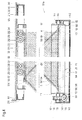
- Figs. 3 (A) and 3 (B) are longitudinal cross sectional views showing a main portion of a single device S1a, where Fig. 3(B) shows a manually operable device for a winding roller.
- Fig. 4 is a lateral cross sectional plan view showing a single device S1a.
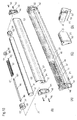
- Figs. 5 (A) to 5 (E) are perspective views and exploded perspective views showing a front winding structure in which a manually operable device is incorporated, where Fig. 5 (B) shows such components as a roller supporting frame, a winding roller and a manually operable device, Fig. 5 (C) shows an enlarged roller end portion and screws for securing the base end portion of a connection wire, and Figs. 5 (D) and 5 (E) show the front end portion of the roller supporting frame from the front and from the rear.
- Figs. 6 (A) to 6 (D) are perspective views and exploded perspective views showing a transverse guide structure for the top hem of a canvas, where Fig. 6 (B) shows such components as a transverse guide frame, a slider and small wheels.
- Fig. 6 (C) shows a state where terminals of connection wires for supporting a projected corner canvas in a tense state are attached to a transverse guide frame together, and
- Fig. 6 (D) shows the front end portion of the transverse guide frame.
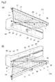
- Figs. 7 (A) to 7 (C ) are exploded perspective views showing a projected corner canvas and wires therefor, where Fig. 7 (C) shows an enlarged portion of the base end portion of a connection wire in the lower right.
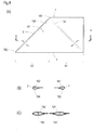
- Figs. 8 (A) to 8 (C° are a plan view showing a projected corner canvas and enlarged cross sectional views showing a state where wires are inserted through the projected corner canvas.
- Fig. 8 (B) shows a cross section of the top hem and the bottom hem of the canvas
- Fig. 8 (C) shows a cross section of along line X-X in Fig. 8 (A) .
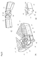
- Figs. 9(A) to 9(D) are perspective views and exploded perspective views showing a front winding structure in which an electric motor is incorporated, where Fig. 9 (B) shows such components as a roller supporting frame, a winding roller and an electric device. Figs. 9 (C) and 9 (D) show the front end portion of the roller supporting frame front and from the rear.
- Figs. 10 (A) to 10 (D) are perspective views and exploded perspective views showing a front winding structure into which a coil spring is incorporated.
- Figs. 11 (A) to 11 (D) and Figs. 12 (A) to 12 (D) are perspective views and plan views showing a projected corner canvas which is stretched into a corner space portion and the process through which the canvas is rolled up and wound, and the reverse order of these views show the process through which the canvas is unwound.
- Figs. 13 (A) to 13 (E) are plan views illustrating the two-stage operation of a single device S1b having foldable arms and showing a projected corner canvas stretching out into the corner space portion and the backward winding process.
- Figs. 14(A) to 14(E) are plan views showing the operation of a single device S2a in the second group and the operation for sliding a winding roller for a projected corner canvas stretching out into the corner space portion and the roller supporting frame to the rear of the device, and then rolling up and storing the spread projected corner canvas.
- Figs. 15 (A) to 15 (C) are plan views illustrating the movement of the roller supporting frame and the foldable arms, where Fig. 15 (B) shows the movement of the projected corner canvas as it is stretched out to the front of the device and recedes to the rear and the movement of the foldable arms as they change in posture as the roller supporting frame recedes step by step, Fig. 15 (C) shows the two as they change in posture when the canvas is wound up step by step ( FIGs. 15 (A) and 15 (B) show the relationship in an enlarged manner between the bracket of a foldable arm and the stopper of an end portion of a link in the top and the bottom).
- Figs. 16(A) to 16(E) are perspective views showing the operation of a single device S2b.
- Figs. 17 (A) to 17 (D) are plan views showing the operation of a single device S3a in the third group, a projected corner canvas which is stretched out into a corner space portion in the process of sliding backward and in the process of being wound up, and the reverse order of these views shows the projected corner canvas in the process of unwinding and spreading, as well as in the process of sliding forward into the corner space portion.
- Figs. 18 (A) and 18 (B) are a longitudinal cross sectional side view showing a main portion of a single device S3a and a front view showing an engaging portion for lateral sliding.
- Figs. 19 (A) to 19 (D) are plan views showing the operation of a single device S3b and a backward winding process where a roller supporting frame translates to the wall portion located diagonally backward while a projected corner canvas stretching out into a corner space portion is being wound up, and the reverse order of these view shows a process where the roller supporting frame is stretched out into a corner space portion located diagonally forward while the projected corner canvas is unwound, in the opposite order.
- Figs. 20 (A) to 20 (C) are longitudinal cross sectional side views showing a main portion of a single device S3b, where Fig. 20 (B) shows a slide guide rail which is attached to the front end portion of a sub-link of a Y-shaped arm, and Fig. 20(C) shows a roller supporting frame which is attached to the front end portion of the main link and a winding roller.
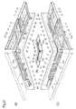
- Figs. 21(A) to 21(C) are perspective views showing a state where two single devices S1a on either side of the projected corner portion face each other and the front end position of an awning device having a conventional structure overlap in the up-down direction in the respective bottom portions on the rear half side, as well as state where the projected corner canvas and the rectangular canvas on one side are spread and the two canvases on the other side are wound up and stored.
- Figs. 22 (A) and 22 (B) are perspective views, one with a transparent portion, showing an awning device WS1c where two single devices S1c on the two sides of the projected corner portion facing each other are interlocked.
- Figs. 23 (A) to 23 (C) are perspective views, one with a transparent state, showing a manually interlocking structure which is incorporated in a corner cap, where Fig. 23(A) shows the manually interlocking structure through a transparent state, Fig. 23 (B) is a perspective view showing the corner portion and Fig. 23(C) shows the corner cap as viewed from the back in a state where it is cut in the vicinity of a portion which is connected with the roller supporting frame.
- Figs. 24 (A) to 24 (C) are perspective views, one with a transparent portion, showing a gear interlocking structure which is incorporated in a corner cap.
- Figs. 25 (A) to 25 (C) are plan views showing the operation of an awning device WS1c having an interlocking structure, where Fig. 25 (A) shows a projected corner canvas when fully spread, Fig. 25(B) shows the projected corner canvas when half spread, and Fig. 25 (C) shows the projected corner canvas when wound up and stored.
- Figs. 26(A) and 26(B) are perspective views with a transparent portion showing an awning device WS1d where two single devices S1d with foldable arms which are freely expandable and retractable are interlocked, and an exploded view showing an arm which is expandable and retractable.
- Figs. 27 (A) to 27 (C) are plan views showing the operation of an awning device WS1d.
- Fig. 28 is a perspective view with a transparent portion showing WS3c where two single devices S3c are interlocked.
- Figs. 29(A) to 29(C) are plan views showing the operation of an awning device WS3c.
- Fig. 30 is a perspective view with a transparent portion showing an awning device WS3a where two single devices S3a are interlocked.
- Figs. 31(A) to 31(C) are plan views showing the operation of an awning device WS3a.
- Figs. 32 (A) to 32 (C) are plan views showing the operation of an awning device WS3d.
- Figs. 33 (A) and 33 (B) are a plan view showing a main portion for illustrating the operation the linking mechanism for integrated roller supporting frames which are interlocked and a view illustrating the movement thereof.
- Figs. 34 to 38 show an embodiment of a complex awning device where an awning device for a projected corner and a rectangular awning device are combined.
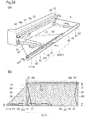
- Figs. 34 (A) and 34 (B) are perspective views showing a complex device SQII1 according to the first embodiment, where Fig. 34 (A) shows the state as viewed from the bottom, and Fig. 34 (B) shows the state as viewed from the top.
- Figs. 35 (A) to 35 (C) are longitudinal cross sectional side views showing a main portion of a complex device SQII1, where Fig. 35(B) shows a roller supporting frame which is attached to the front end portion of a main link and a winding roller, and Fig. 35 (C) shows the front bar of the rectangular canvas attached to the front end portion of a sub-link.
- Figs. 36 (A) to 36 (D) are plan views showing the operation of a complex device SQII1 and the process of winding a projected corner canvas stretching out to the corner space portion and the rectangular canvas spread to the front.
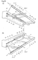
- Figs. 37(A) and 37(B) are a perspective view with a transparent portion and a plan view showing a complex device SQII2 according to the second embodiment, where a rectangular canvas and a winding roller are extended to the vicinity of the corner of the front end portion of the device.
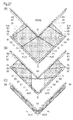
- Figs. 38 (A) and 38 (B) are a perspective view with a transparent portion and a plan view showing a complex device SQII3 according to the third embodiment, where the projected corner canvas is in an approximate triangular form.
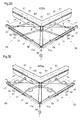
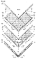
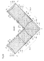
- Fig. 39 is a plan view showing an awning device WSQIV1 where two complex devices SQII4 on the two sides of the projected corner portion which face each other are interlocked.
- Fig. 40 is a plan view showing an awning device WSQIV2 where two complex devices SQII5 having a rectangular canvas and a winding roller for the canvas which extend to the vicinity of the corner of the projected corner portion and the projected corner canvas, which is a triangular canvas, are interlocked.
- movable awing devices WS1c, WS1d, WS3c, WS3a and WS3d where two single devices S1c, S1d, S3c, S3a, and S3d which face each other on the two sides of the projected corner portion N1 are interlocked as shown in Figs. 22 to 33 are described.
- movable awning devices SQII1 to 3 which are formed by combining an awning device for a projected corner S4a, S4b, S5a or S5b having a front winding structure for projected corner canvases G1, G2 and rectangular awning devices Q1, Q2 having a rear winding structure for rectangular canvases P1, P2, and the embodiments of movable awning devices WSIV1 and 2, where the two awning devices are interlocked, are described.
- the single devices S1a, S1b, S2a, S2b, S3a and S3b of the present invention can be roughly categorized into roughly three types of embodiments with the transverse guide structure of the projected corner canvas G1 provided on the wall side and the structure for winding a canvas provided on the front side being approximately the same and the foldable arms and the transverse sliding structure of the front end portion of the arms modified in various ways.
- the single devices S1a and S1b in the first group are formed of a transverse guide frame K1 which is attached to a wall portion close to the corner of the projected corner portion N1, a roller supporting frame F1 which is attached to the front end portion of foldable arms I1, I2, L1 and L2, winding rollers J1 to J3 having a manually or electrically operable structure supported by the supporting frame F1 through bearings, and a projected corner canvas G1 stretched between the winding rollers J1 to J3 and the slider 22 incorporated in the above described transverse guide frame K1.
- the transverse guide frame K1 is formed in a box frame form of an upper plate portion 211 of which the top is in one-side roof form, a front plate portion 212 and a rear plate portion 213, which are vertical, and a horizontal bottom plate portion 214, and from among these, the rear plate portion 213 on the rear surface is secured to wall portion.
- Reference numeral 215 is guide trenches for the slider 22 and created on the front and rear sides of the inner upper portion of the transverse guide frame K1 in the longitudinal direction.
- Reference numeral 216 is an opening in the lower half of the front plate portion 212 through which the front end of the slider 22 slightly protrudes to the front.
- the slider 22 is formed of a steel frame main body 221 which is flat and pairs of small wheels 231 are attached to upper surface portions located in the front and rear of the frame main body in such a manner so as to be freely rotatable, laterally. From among these, small wheels 231 face axis holes 222 provided on both sides, front and rear, of the frame main body 221 and axis pins 232 inserted from above are screwed into a screw hole in the support plate 233 which is inserted through the inside portion in the front-rear direction of the frame main body 222 and secured.
- the small wheels 231 of the slider 22 are fitted in the guide trenches 215 in such a manner so as to be freely slidable, so that the slider 22 slides along the transverse guide frame K1 with the wheels rotating.
- Reference numeral 223 is a canvas engaging trench created in the lower portion of the front end of the frame main body 221, and reference numeral 224 is a wire attaching hole which penetrates through a portion in the vicinity of the front end of the canvas engaging trench 223 in the up-down direction.
- Reference numeral 241 and 242 are end caps which are fitted to the both end portions, front and rear, of the transverse guide frame K1.
- I1 and I2 are pairs of straight foldable arms (hereinafter referred to as I-shaped arms) which are attached in parallel at a distance from each other in the front and rear, and a casing for supporting winding rollers J1, J2 through bearings (hereinafter referred to as roller supporting frame F1) is attached to the front end portion of the foldable arms, which are pressed and supported in such a manner so that they can be pushed out in parallel diagonally forward from a wall portion or freely rotate in parallel, diagonally backwards.
- Reference numerals 261 and 262 are brackets for supporting the both end portions of I-shaped arms I1, I2 around the pins, and from among these, the brackets 261 for the arm base end portion are attached directly to the corner location of the projected corner portion N1 in the vicinity of the lower portion at the front end of the transverse guide frame K1 and on the front wall W1 in the vicinity of the middle of the transverse guide frame K1, which is placed at an appropriate distance to the rear from the corner portion, or indirectly secured via an appropriate rear supporting frame (not shown)so that the angle of inclination of the I-shaped arms I1, I2 can be freely adjusted if necessary.
- brackets 262 of the front end portion of the arm are secured in the vicinity of the middle of the roller supporting frame F1 and in a location in the lower portion of the rear surface of the rear end portion of the roller supporting frame F1 at the same distance as the above described brackets 261.
- a spring (not shown) is incorporated in the axis portion in one or both of the base end portion and the front end portion of the I-shaped arms I1, I2 so that the I-shaped arms I1, I2 which are folded up in the wall portion rotate in parallel in the direction of spreading by means of the elastic force of the spring, and thus, the roller supporting frame F1 is pushed out diagonally forward in parallel.
- I-shaped arms I1, I2 rotate in parallel against the elastic force of the spring and translate the roller supporting frame F1 to the wall portion diagonally backward.
- the roller supporting frame F1 is formed of a front plate portion 121 of which the front is in a gradual semi-arc form, a horizontal upper eaves portion 122 and a bottom plate portion 123 and a rear plate portion 124 which is inclined upward to the rear, and has a longitudinal cross section in an approximate wedge form, so that a portion of the upper eaves portion 122 extending from the rear end to the rear portion and an upper half portion of the rear plate portion 124 creates a space portion 131 with an opening inside which the winding roller J1 is incorporated.
- Reference numeral 125 has holes through which water is let out and created in the vicinity of the both sides, front and rear, of the bottom plate portion 123.
- Reference numerals 141 and 142 are end caps which are fitted to both end portions, front and rear, of the roller supporting frame F1 and are secured with screws 146, and the bearing portions 143 and 144 provided with round holes protrude from the rear upper portion of the inner surface of the end caps.
- Reference numeral 11 is a roller main body in cylindrical form which forms the winding roller J1, and a canvas engaging trench 111 is created therein, in the direction of the axis.
- Reference numerals 151 and 152 are end caps which are fitted to the both end portions, front and rear, of the roller main body 11, and support axes 153 and 154 which penetrate through and are secured to the cap main body are fitted to the above described bearing portions 143 and 144 in such a manner so as to be freely rotatable.
- Reference numeral 161 is a worm gear which is engaged with and secured to the support axis 153 of the end cap 151
- reference numeral 162 is a worm gear which engages with the worm gear 161 and the axis around which the worm gear rotates 163 is supported vertically in the upper and lower bearing portions 145 inside the above described end cap 141, and a hook 164 which engages with an operation rod (not shown) is formed in the lower end portion of the axis around which the worm gear rotates 163.
- the winding roller J1 can be operated manually and freely rotated forward and backward.
- the projected corner canvas G1 is formed of tent cloth made of fabric or a synthetic resin in an approximate trapezoid form with right angles when spread, and made up of a canvas main body portion X1 in rectangular form and a canvas protrusion X2 in right triangle form which protrudes to one side.
- the top hem 1 in the upper end portion of the canvas (hereinafter referred to as canvas top hem) and the bottom hem 2 in the lower end portion of the canvas (hereinafter referred to as canvas bottom hem) are parallel to each other, and a diagonal side 3 having an angle of inclination of approximately 45 degrees (hereinafter referred to as canvas diagonal side) extends between the front end portion of the canvas bottom hem 2 and the front end portion of the canvas top hem 1 in such a manner so as to spread toward the bottom, and a vertical side 4 (hereinafter referred to as canvas vertical portion) extends between the rear end portion of the canvas bottom hem 2 and the rear end portion of the canvas top hem 1.
- canvas top hem a diagonal side 3 having an angle of inclination of approximately 45 degrees
- canvas vertical side 4 (hereinafter referred to as canvas vertical portion) extends between the rear end portion of the canvas bottom hem 2 and the rear end portion of the canvas top hem 1.
- Reference numerals 181 and 182 are through holes in a bag form created through the canvas top hem 1 and the canvas bottom hem 2, and a fixture member, such as wires 183 and 184, a tube or a rope, is inserted into these holes.
- Reference numeral 191 is a through hole in a bag form created along a line which diagonally connects the front end portion of the canvas top hem 1 and the rear end portion of the canvas bottom hem 2
- reference numeral 192 is a through hole in a bag form created in the canvas diagonal side 3
- the two through holes 191 and 192 thus created diagonally form a mountain shape in a plan view.
- a tense member for the projected corner canvas G1 such as connection wires 193, 194, a belt or a rope, is inserted into the through holes 191 and 192, and from among these, engaging pieces 195 and 196 of the wire front end portions are pulled out downward from the openings at the lower end of the through holes 191 and 192, and the wire terminal portions are drawn out upward from the opening at the top of the through holes 191 and 192.
- the canvas bottom hem 2 is made to face the canvas engaging trench 111 of the winding roller J1, so that the wire 184 is inserted through the through hole 182, and thus, the canvas bottom hem 2 is secured in such a manner so that it cannot be pulled out.
- screws 101 are screwed in the front and rear of the canvas engaging trench 111, and in addition, the engaging pieces 195 and 196 of the connection wires 193, 194 which are pulled out through the opening in the lower end portion are fitted to the above described engaging trench 111, and screws 102 are screwed in from the outside, so that the engaging pieces 195 and 196 are sandwiched and secured.
- the top hem 1 of the projected corner canvas G1 is made to face the canvas engaging trench 223 of the slider 22 and the wire 183 is inserted through the through hole 181 of the canvas top hem 1, and thus, the top hem 1 is secured in such a manner so that it cannot be pulled out.
- connection wires 193, 194 drawn out from the opening at the top are inserted through the attachment holes 224 of the slider 22 shown in Figs. 4 and 6(C) from the bottom to the top, and in addition, screws 103 are screwed in from the front end portion of the canvas engaging trench 223, and thus, the two wire terminal portions are secured in the attachment holes 224 through pressure.
- the projected corner canvas G1 is spread and supported between the winding roller J1 and the slider 22 in an appropriate tense state.
- winding roller J2 in the second example shown in Figs. 9(A) to 9(D) rotates forwards and backwards by means of an electrical motor M1 in cylindrical form which is built-in inside the roller main body 11.
- the electrical motor M1 is inserted in the front portion of the roller main body 11, and a motor output axis 371 and a securing axis portion 372 are provided in the rear and front end portions of the electrical motor M1, respectively.
- Reference numeral 381 is a movement conveying socket having a trench which engages with the roller main body 11, and the motor output axis 371 is fitted to the axis hole 382 of the socket.
- Reference numeral 155 is a through hole of the end cap 151, and the front end portion of the electrical motor M1 is supported in the through hole 155 through bearings.
- the movement conveying socket 381 is engaged with and secured to the motor output axis 371, and in addition, the electrical motor M1 is inserted in the front portion of the roller main body 11 and the end cap 151 is inserted into the front end portion of the electrical motor M1, and then fitted to the front end portion of the roller main body 11 on the left side, so that the axis portion 372 of the electrical motor M1 is engaged with and secured to a flat hole (square hole also possible) in the bearing portion 145 of the end cap 141.
- the electrical motor M1 is incorporated inside the roller main body 11.
- the output axis 371, the movement conveying socket 381 and the roller main body 11 integrally rotate forward and backward, so that the winding and unwinding operation of the projected corner canvas G1 is automated and energy can be saved.
- the projected corner canvas G1 is wound around the winding rollers J1, J2 from above with the rear surface of the canvas bottom hem 2 on the inside and the front surface on the outside in the process shown in Figs. 11 (B) to 11(D) and 12(B) to 12(D) .
- the I-shaped arms I1, I2 rotate in parallel to the rear against the elastic force of the spring incorporated in the base end portion and folded while translating the roller supporting frame F1 toward the wall portion diagonally backward.
- the tensile force of the projected corner canvas G1 generated as the canvas is wound is applied to the slider 22 of the canvas top hem 1, and in addition, the tensile force resulting from the connection wires 193, 194 is applied to the front end portion of the slider 22, and as a result, the slider 22 of the canvas top hem 1 moves backward while slid and guided along the transverse guide frame K1.
- the projected corner canvas G1 is wound around the winding rollers J1, J2 and the I-shaped arms I1, I2 are folded up and collapsed in a wall portion, and overlap with the roller supporting frame F1 when stored in a wall in a compact manner.
- connection wires 193, 194 are pulled back, so that the slider 22 of the canvas top hem 1 slides along the transverse guide frame K1, and in addition, prevent the canvas from changing in form in a plane when the projected corner canvas G1 is wound up, and thus, make it possible to smoothly and regularly wind the projected corner canvas G1.
- the canvas bottom hem 2 having a great width for winding is on the inner surface side, and the width for winding becomes gradually shorter, and in the end, the canvas top hem 1 having a short width is wound up.
- the projected corner canvas G1 wound up around the winding rollers J1, J2 is unwound, and the elastic force applied to the I-shaped arms I1, I2 folded in the inner wall portion is released so that the pressing force rotates the I-shaped arms I1, I2 in such a direction that they open and spread, and as shown in Figs. 11 (D) to 11(A) and 12(D) to 12(A) , the winding rollers J1, J2 and the roller supporting frame F1 are pushed out so as to translate toward the corner space portion diagonally forward.
- the elastic pressing force of the I-shaped arms I1, I2 applied to the roller supporting frame F1, the tensile force of the projected corner canvas G1, and the tensile force of the unwound connection wires 193, 194 make the tensile force applied to the slider 22 in the forward direction so that the slider 22 slides along the transverse guide frame K1 so as to move forward.
- two single devices S1a are abutted against each other at a right angle (obtuse angle or acute angle also possible depending on the angle of the projected corner portion) and attached to locations in the corner between the front wall W1 and the side wall W2, and in addition, when the projected corner canvases G1 wound up around the respective winding rollers J1, J2 are unwound, the two projected corner canvases G1 are spread and stretched out in such a state that they face each other in a direction diagonally forward, and thus, the peripheral appearance of the building, including the corner space portion in the projected corner portion N1, is covered so as to provide a good appearance.
- the winding roller J3 in the third example shown in Fig. 10 is incorporated in the case where it functions as a following roller.
- the winding roller J3 is adopted in the case where, for example, the I-shaped arms I1, I2 of the single apparatus S1a are provided on the drive side shown in Figs. 42 to 44 of the present applicant's prior application 1 (see Patent Document 1), or in the case where winding rollers 30, 31a of the rectangular awning devices Q1, Q2 in the complex devices SQII1 to 5 shown in Figs. 34 to 40 , which are described in the following, are provided on the drive side.
- reference numeral 47 is a coil spring of the roller main body 11
- reference numeral 49 is a fixed axis for supporting the coil spring 47 around it
- reference numeral 48 is a bearing socket for the fixed axis 49 and the coil spring 47.
- the rear end portion 492 of the fixed axis 49 is fitted to the center through hole 481 of the bearing socket 48, and in addition, the rear end portion 472 of the coil spring 47 mounted around the fixed axis 49 is fitted to the through hole 482 in a decentralized location of the bearing socket 48.
- the front end portion 491 of the fixed axis 49 penetrates through the center through hole 156 of the end cap 151 and is fitted into a square hole of the bearing portion 145 of the end cap 141, and in addition, the front end portion 471 of the coil spring 47 is inserted and fitted to the through hole 157 of the end cap 151.
- the coil spring 47 is incorporated into the front portion of the roller main body 11.
- the coil spring 47 is gradually compressed by means of the end cap 151 of the roller main body 11 so that the elastic energy is stored in the coil spring 47 or the stored elastic energy is released.
- the L-shaped arms L1, L2 are formed of a rear link 271 and a front link 272 which are connected so as to be freely foldable, and the connection portion which is foldable in two is connected through a connection rod 273 which crosses the two links.
- a spring having a relatively weak elasticity is incorporated into the bracket 261 portion in the base end portion of the L-shaped arms L1, L2, that is to say, into the base end portion of the rear link 271, and in addition, a spring having a relatively strong elasticity is incorporated into the foldable connection portion between the rear link 271 and the front link 272.
- the pair of front links 272 which are pressed with a spring having a stronger elasticity make the roller supporting frame F1 translate diagonally backward against the elastic pressing force, and the slider 22 of the top hem 1 of the canvas slides backward to the rear half portion of the guide frame along the transverse guide frame K1, and thus, the front links 272 are folded up into a wall portion through the fluctuating process shown in Figs. 13(C) to 13(E) .
- the projected corner canvas G1 is wound up around the winding rollers J1, J2 as shown in Fig. 13(E) , and in addition, the L-shaped arms L1, L2 are folded in such a state so as to be pressed and spread against a wall portion and stored in a wall in a compact manner in such a state so as to overlap with the roller supporting frame F1.
- the pair of front links 272 pressed by a spring having a stronger elasticity first rotate in parallel diagonally forward due to the elastic pressing force, and the roller supporting frame F1 is pushed out so as to translate diagonally forward, and in addition, the slider 22 of the top hem 1 of the canvas is transversely slid along the transverse guide frame K1 so as to move forward in the vicinity of the middle of the guide frame.
- the link mechanism formed of L-shaped arms L1, L2 and the connection rod 273 makes the roller supporting frame F1 in the front end portion of the arm translate toward the corner space portion diagonally forward through the bending and stretching movement in two stages, and therefore, it becomes possible to further push out the roller supporting frame F1 diagonally forward in comparison with the case where I-shaped arms I1, I2 are incorporated into the single device S1a in the first embodiment.
- single devices S2a and S2b in the second group are formed of a transverse guide frame K1 attached to a wall portion in the projected corner portion N1, a roller supporting frame F1 attached to the front end portions of the foldable arms V1, V2, winding rollers J1, J2 supported by the supporting frame F1 through bearings, and a projected corner canvas G1 attached to the winding rollers J1, J2 and a slider 22.
- V-shaped arms This is formed by replacing the I-shaped arms I1, I2 in the first embodiment with a pair of foldable arms in lateral V shape V1 and V2 (hereinafter referred to as V-shaped arms), front and rear, and in addition, providing an engaging portion for a transverse operation 28 (engagement hole also possible) shown in Fig. 18 (B) which protrudes in a portion at the bottom of the roller supporting frame F1.
- a bracket 261 in the base end portion of the V-shaped arm V1 is attached in the corner end portion of the projected corner portion N1, and a bracket 262 in the front end portion is attached in the vicinity of the front end of the roller supporting frame F1.
- a bracket 261 in the base end portion of the V-shaped arm V2 is attached to a location in the lower rear portion of the transverse guide frame K1 located at a point approximately 3/4 of the entire length from one end, that is to say, a location in the lower rear portion located at a point approximately 1/4 of the entire length from the rear end of the transverse guide frame K1, and likewise, a bracket 262 in the front end portion is attached to a location at a point approximately 1/4 from the rear end portion of the roller supporting frame K1.
- reference numeral 201 is a stopper formed so as to protrude from one side of the rear end portion of the rear link 251
- reference numeral 202 is a stopper protruding from one side of the front end portion of the front link 252 and at the stage shown in Fig.
- the projected corner canvas G1 that spreads to the front is positioned when wound around the winding rollers J1, J2, and the V-shaped arms V1, V2 are folded in two, maintaining symmetry between the front and the rear, and thus, the winding rollers J1, J2 and the roller supporting frame F1 translate linearly in the front and rear directions.
- the engagement portion 28 is grasped and pulled backwards.
- the projected corner canvas G1 is pulled backwards while maintaining its spread state, and following this, the slider 22 of the top hem 1 of the canvas also moves backwards along the transverse guide frame K1.
- the V-shaped arms V1, V2, which are pressed so as to open at an angle ⁇ 1 are slightly folded inwards against the pressing force for opening and spreading the arms, and as shown by a number of imaginary lines in Fig.
- connection portion at which the V-shaped arm V1 is folded in two at the front of the device is pulled up slightly diagonally backward so that the arm rotates and swings
- connection portion at which the V-shaped arm V2 is folded in two in the rear of the device is slightly pulled downwards diagonally to the bottom so that the arm rotates and swings, and thus, the arms change their form as shown by the solid lines in Fig. 15 (B) when folded into a V shape, maintaining symmetry between front and rear.
- roller supporting frame F1 of the winding rollers J1, J2 slides in parallel to the rear of the device as shown in Figs. 14 (B), 14(C) and 15(B) so that the slider 22 of the top hem 1 of the canvas is pulled down to the rear half of the transverse guide frame K1.
- the operation rod (not shown) is engaged with the hook 164 of the manually operable device and rotated.
- the electrical motor M1 is driven for winding the canvas.
- the projected corner canvas G1 is wound up around the winding rollers J1, J2 with the front surface of the bottom hem 2 of the canvas facing the outside and the rear surface facing inside as shown by a number of imaginary lines in Figs. 14 (C) to 14(E) and 15(C) .
- the V-shaped arms V1, V2 are folded against the elastic pressing force due to a spring or the like incorporated in the connection portion that is folded in two so that the winding rollers J1, J2 and the roller supporting frame F1 translate linearly toward the rear and toward a wall portion, and the entirety of the device is folded into a wall portion in a compact manner so as to be contained.
- the operation rod which is engaged with the hook 164 of the manually operable device is rotated in the direction opposite to that above through the operation, or the electric motor M1 is driven so as to rotate in the direction of unwinding.
- the projected corner canvas G1 that has been wound around the winding rollers J1, J2 is unwound, and the elastic resilience of the V-shaped arms V1, V2 that have been folded in a wall portion is released, so that the V-shaped arms V1, V2 are rotated by means of the pressing resilience in such a direction as to spread, and the winding rollers J1, J2 and the roller support frame F1 are pushed out linearly to the front while moving in parallel.
- the projected corner canvas G1 is unwound to the front of the front wall W1 so as to spread and be supported in a tense state.
- the stopper 202 of the front link 25 of the V-shaped arm V1 prevents the V-shaped arm V1 from spreading further
- the stopper 201 of the rear link 251 of the V-shaped arm V2 prevents the V-shaped arm V2 from spreading further.
- the spread projected corner canvas G1 is prevented from spreading further to the front.
- the projected corner canvas G1 is prevented from moving to the rear of the device by the above described stoppers 202 and 201 while in a freely and transversely slidable state to the corner space portion in the front of the device.
- the front end hook portion of an operation rod (not shown) is engaged with the engagement portion 28 of the roller supporting frame F1 from beneath, and then, the roller supporting frame F1 is slid toward the corner space portion of the projected corner portion N1 or laterally pushed out toward the corner space portion while grasping the engagement portion 28.
- the spread projected corner canvas G1 and the roller supporting frame F1 slide toward the corner space portion in the front of the device, and at this time, the slider 22 of the top hem 1 of the canvas slides forward when moving along the transverse guide frame K1.
- the projected corner canvas G1 moves forward, as shown in Figs. 14(B), 14(A) , 15(B) and 15(A) , so that the canvas spreading portion X2 is pushed out toward the corner space portion of the projected corner portion N1.
- the front link 252 of the V-shaped arm V1 is gradually drawn out to the front of the device from the crossing angle ⁇ 2 in Fig. 15 (B) , and thus changes so as to have a gradual inclination at the crossing angle ⁇ 1 in Fig. 15 (A) , and in addition, the angle at which the front link 252 and the rear link 251 are folded in two gradually spreads from a state where the angle ⁇ 2 at which the front link 252 and the rear link 251 are folded in two is approximately "less than 90 degrees," while the rear link 251 is raised so that the angle ⁇ 1 at which the link is folded into two as shown in Fig. 15 (A) becomes approximately "130 degrees" and further rotation is thereby prevented.
- the front link 252 of the V-shaped arm V2 is drawn out gradually to the front of the device from the crossing angle ⁇ 2 in Fig. 15 (B) , and thus changes so as to have a steep inclination of the crossing angle ⁇ 1 in Fig. 15(A) , and in addition, the angle ⁇ 2 at which the front link 252 and the rear link 251 are folded in two gradually spreads from approximately "less than 90 degrees,” and at a stage where the angle ⁇ 1 at which the link is folded in two as shown in Fig. 15 (A) becomes approximately "130 degrees,” further rotation is prevented.
- the projected corner canvas G1 which spreads into the corner space portion and the roller supporting frame F1 change in state while the angle at which the V-shaped arms V1, V2 are folded in two spreads to " ⁇ 1 from ⁇ 2," and at the stage of the crossing angle ⁇ 1, the V-shaped arms V1, V2 are prevented from rotating further, and thus, a stable state where the canvas is spread and stretched out can be achieved.
- the width to which the projected corner canvas G1 is unwound to the front and the length of the connection wires 193, 194 are limited, and thus, the angle at which the V-shaped arms V1, V2 half spread can be appropriately adjusted. In this case, it is not necessary to restrict the angle of the rear link 251 or the front link 252 using the stoppers 201 and 202.
- the base end portion and the front end portion of the V-shaped arm V2 in the rear of the device can be attached in the vicinity of the rear end of the transverse guide frame K1 and the roller supporting frame F1.
- the single device S2b shown in Figs. 16(A) to 16(E) is provided in the case where the length of the links, including the rear links 251 and the front links 252 of the V-shaped arms V1, V2, is relatively long in comparison with the case of the third embodiment, the location in which the V-shaped arm V1 is attached in the front of the device is the same, and the location in which the V-shaped arm V2 is attached in the rear of the device is different, and the bracket 261 in the base end portion of the V-shaped arm V2 is attached in a lower portion at the rear end of the transverse guide frame K1 while the bracket 262 in the front end portion is attached to the rear end portion of the roller supporting frame F1.
- the V-shaped arm V1 is folded into a reverse L shape at a stage where the projected corner canvas G1 stretches out into the corner space portion, and thus, the front link 252 overlaps with the front half lower portion of the roller supporting frame F1, and the rear link 251 is placed in a vertical state as viewed in a plan view.
- the V-shaped arm V2 in the rear of the device is folded in an upside-down L shape, and thus, the rear link 251 overlaps with the rear half lower portion of the transverse guide frame K1, and the front link 252 becomes vertical as viewed in a plan view showing the configuration of the links.
- the V-shaped arms V1, V2 are half open with the angle ⁇ 2 at which the V-shaped arms V1, V2 are folded in two at approximately "60 degrees" in the case of Fig. 16 (C) .
- Fig. 16 (A) when the roller supporting frame F1 of the projected corner canvas G1 which is stretched out into the corner space portion slides to the rear of the device, the V-shaped arms V1, V2 are folded in two, as shown in Fig. 16(C) , with the state shown in Fig. 16(B) in between, and a half-open state where the angle at which the arms are folded in two is approximately "60 degrees" is maintained.
- the single device S3a according to the fifth embodiment shown in Figs. 17 (A) to 17(E) and 18(A) is described below.
- guide protrusions 126 and 127 are provided on the rear surface of the front plate portion 121 at a distance in the up-down direction, and guide trenches are created in upper and lower locations on the inside of the rear end.
- guide protrusions 126 and 127 for the roller supporting frame F1a are engaged in the both end portions, upper and lower, of the rail portion 331 of the transverse guide rail R1, so that the roller supporting frame F1a slides along the transverse guide rail R1.
- an operation rod (not shown) is engaged with the hook 164 of the manually operable device and rotated.
- the electrical motor M1 is driven to wind up the canvas.
- the projected corner canvas G1 is wound up around the winding rollers J1, J2 with the front surface of the bottom hem 2 of the canvas facing outward and the rear surface facing inward, as shown in Figs. 17(B) to 17(D) .
- the operation rod which is engaged with the hook 164 of the manually operable device is rotated in the direction opposite to that above through the operation, or the electric motor M1 is driven so as to rotate in the direction of unwinding.
- the front end hook portion of the operation rode (not shown) is engaged from beneath with the engaging portion 28 of the roller support frame F1a, and after that, the front end hook is slid toward a corner space portion through operation.
- the projected corner canvas G1 moves forward while maintaining its spread state, as shown in Figs. 17(B) and 17(A) , so that the canvas spreading portion X2 is stretched out into the corner space portion, and the outside of the building including the corner space portion of the projected corner portion N1 is covered.
- the Y-shaped arm Y1 is formed of a main link 291 and a sub-link 292 having approximately half the length of the main link 291, of which the rear end portion is supported around a pin in the vicinity of the middle portion of the main link.
- a link portion made up of a link rear half portion of the main link 291 and a sub-link 292 in the Y-shaped arm Y1 and the V-shaped arm V2 in the rear of the device are folded against the elastic pressing force due to a spring or the like which is incorporated in the connection portion which is foldable in two, as shown in Figs. 19(B) to 19(D) , and from among these, the front end portion of the main link 291 rotates to the rear against the elastic pressing force, due to a spring or the like incorporated in the base end portion, and thus, the canvas is pushed and spread.
- the roller supporting frame F1a is guided and slid to the rear along the transverse guide rail R1 while the entire device translates toward a wall portion diagonally backward, and at the same time, the tensile force of the projected corner canvas G1 generated when the canvas is wound up is applied to the slider 22 of the top hem 1 of the canvas, and in addition, the tensile force of the connection wires 193, 194 is applied to the front end portion of the slider 22, and as a result, the slider 22 moves backward along the transverse guide frame K1.
- the projected corner canvas G1 is wound around the winding rollers J1, J2 of the roller supporting frame F1a so as to be stored in a wall.
- the elastic pressing force to the front of the main link 291 of the Y-shaped arm Y1 which is applied to the roller supporting frame F1a, the tensile force of the projected corner canvas G1 and the tensile force of the connection wires 193, 194 to be unwound apply a tensile force to the slider 22 of the top hem 1 of the canvas in the direction toward the front and make the slider 22 slide and move forward along the transverse guide frame K1.
- the projected corner canvas G1 is stretched out around the outside of the building including the corner space portion of the projected corner portion N1, as shown in Fig. 19(A) .
- the foldable arms are a combination of the above described Y-shaped arm Y1 and V-shaped arm V2
- winding and unwinding of the projected corner canvas G1 and translation of the roller supporting frame F1a are carried out efficiently and in synchronization, as compared with the case where the V-shaped arms V1, V2 shown in the fifth embodiment are combined.
- the linear section in the rear half portion of the above described single devices S1a, S1b, S2a, S2b, S3a and S3b can be combined with conventional structures for spreading and winding a rectangular canvas P1, that is to say, a movable awning device Q having a rear winding structure (hereinafter referred to as conventional device), as shown in Figs. 21(A) to 21(C) .
- conventional device a movable awning device Q having a rear winding structure
- K2 is a casing for winding and storing a rectangular canvas P1 and a winding roller 30 which rotates forward and backward through manual operation or electric power operation is incorporated inside the casing, where the top hem of the rectangular canvas P1 is attached.
- Reference numeral 31 is a front bar for securing the bottom hem of the rectangular canvas P1, and it is desirable for it to have approximately the same form as the above described roller supporting frames F1, F1a, or the same form as the front bar R2 shown in Figs. 35(A) to 35(C) .
- V3 and V4 are a pair of V-shaped arms which are freely foldable in two, where a spring or a wire or the like presses the V-shaped arms V3 and V4 in such a direction that the arms are pushed and spread, in the same manner as in the case of the V-shaped arms V1, V2 in the fifth embodiment.
- the winding roller 30 of the conventional device Q when the winding roller 30 of the conventional device Q is wound and rolled by means of a manually operable handle or an electric motor (not shown), the winding roller 30 winds the rectangular canvas P1 with the rear surface facing inward and the front surface facing outward, and thus, the canvas is wound from above, while the V-shaped arms V3 and V4 are folded inward against the elastic resilience of the arms, so that the front bar 31 moves in parallel and is stored in the wall.
- the above described single devices S1a, S1b, S2a, S2b, S3a and S3b have an inner slider structure where a slider 22 is incorporated inside a transverse guide frame K1 which is attached to wall portion of the projected corner portion N1 in such a manner so as to be freely rollable, and the top hem 1 of the projected corner canvas G1 is fitted into the canvas engaging trench 223 of the slider 22, but may have an outer slider structure.
- the single device S1a, S1b, S2a, S2b, S3a or S3b in the first to sixth embodiments is attached to one corner portion of the projected corner portion N1 or two of these are attached to the two corner portions of the projected corner portion N1 so as to face each other so that these are individually and manually operated or driven by a motor
- the following seven to eleven embodiments are embodiments relating to a case where two of the single devices S1c, S1d, S3c, S3a and S3d belonging to the first and third groups are made to face each other in two portions of the projected corner portion N1 so as to provide a interlocking structure.
- the movable awning device WS1c according to the seventh embodiment shown in Figs. 22 (A), 22(B) , 25(A) to 25(C) is described below.
- This awning device WS1c corresponds to a case where two single devices S1c on the two sides of the projected corner portion N1 face each other, and the front end portions of the roller supporting frames F1 attached to the front end portions of the V-shaped arms V1, V2 are abutted against each other at a right angle so that the end portions at which they are abutted against each other are connected and integrated through the manually operable interlocking structure shown in Fig. 23 (A) or the corner cap 341 in which the gear interlocking structure shown in Fig. 24 (A) is incorporated.
- the two roller supporting frames F1 are connected and integrated in L shape, as viewed in a plane.
- the V-shaped arms V1, V2 are respectively formed of a rear link 251 and a front link 252 which are connected so as to be freely foldable in two to the rear and a connection rod 253 inserted to the connection portion which is foldable in two between the V-shaped arms V1, V2 so that a link is formed.
- the base end portion of one V-shaped arm V1 is attached to a lower portion at the front end of the transverse guide frame K1 in the vicinity of the corner of the projected corner portion N1, and the front end portion thereof is attached to the lower portion at the front end of the roller supporting frame F1 while the base end portion of the other V-shaped arm V2 is attached to the lower portion in the vicinity of the middle of the transverse guide frame K1, and the front end portion thereof is attached in the vicinity of the lower portion in the middle of the roller supporting frame F1.
- a spring for pressing the base end portion of the V-shaped arms V1, V2, that is to say, in the base end portion of the rear link 251, in such a direction that the arms open is incorporated in the base end portion of the V-shaped arms V1, V2, and in addition, a spring (not shown), for pressing the two links 251 and 252 in such a direction that the arms open, is incorporated in the connection portion which is foldable in two between the rear link 251 and the front link 252.
- Reference numeral 343 is a bearing portion formed inside the corner cap 341, a worm gear 162 is fitted into an upper portion, and a rotational axis 163, where a hook 164 is formed, is supported vertically by the lower end portion.
- Reference numeral 342 is a bearing portion which is horizontally formed inside the cap where axis holes provided on two sides forming a right angle support two winding rollers J1 in which a worm gear 161 which engages with the above described worm gear 162 is fitted, respectively, through bearings.
- the two winding rollers J1 interlock through gears so as to be freely rotatable forwards and backwards when manually operated.
- the roller supporting frames F1 which are connected and integrated move backwards linearly to the rear parallel to the center line which equally divides the projected corner portion N1 into two while the roller supporting frames F1 translate towards the corresponding front wall W1 and side wall W2 so as to be retracted to the respective sides of the projected corner portion N1 and contained in wall portions.
- the respective V-shaped arms V1, V2 stretch to the front due to the elastic pressing force so that the connected and integrated roller supporting frames F1 translate diagonally forward and are linearly pushed out, and thus, the projected corner canvas G1 is stretched out into the corner space portion.
- This awning device WS1d corresponds to a case where the link mechanism made up of the V-shaped arms V1, V2 and the connection rod 253 in the first embodiment is replaced with a pair of foldable arms T1, T2 which are parallel to each other and of which the length of the arms is variable (hereinafter, referred to as expanding and contracting arms), two single devices S1d on two sides of the projected corner portion N1 face each other, and a gear interlocking device as shown in Figs. 23(A) and 24(A) is incorporated in the end portions of the roller supporting frames F1, which are abutted against each other.
- the expanding and contracting arms T1, T2 are formed by inserting and supporting an inner pipe 252 on the front side into an outer pipe 351 on the rear side so as to freely expand or contract by means of a coil spring 353 or an elastic body made of rubber or the like, which is incorporated inside.
- the two roller supporting frames F1 are connected and secured to each other at the front end portions through the corner cap 341, and therefore, the two expanding and contracting arms T1, T2 rotate to the rear in arc form at the same time that the outer pipe 351 and the inner pipe 352 rotate to the rear while expanding or contracting relative to each other so as to eventually be folded into a wall portion as shown in Fig. 27(C) .
- the two roller supporting frames F1 are pulled towards the corner portion of the projected corner portion N1 and stored in the wall.
- the two roller supporting frames F1a are linked and secured through the front end portions thereof, and therefore, the two I-shaped arms I1, I2 rotate to the rear and slide the transverse guide rail R1 to the rear along the roller supporting frames F1a as shown in Fig. 29(B) , and then slide the rail forward so as to rotate to the rear and eventually be folded in a wall portion, and at the same time, the integrated roller supporting frames F1a are pulled towards the corner portion so as to be stored in the wall.
- reference numeral 254 is a bent link which is formed so as to protrude from the front end portion of the front link 252 in the V-shaped arm V1 and be bent at approximately a right angle to the outside, and the portion thereof in the vicinity of the bent portion is supported around a pin by the bracket 263 attached to the front end portion of the front bar F1a.
- the complex device WS3d changes its form as shown in Figs. 32(A) to 32(C) , and at the same time, is drawn into the two wall portions so as to be contained in a compact manner.
- the rear link 251 and the front link 252 are folded and stored in the corner end portion on the front side W1 of the projected corner portion N1, and the bent link 254 and the connection rod 78 enter into the corner end portion on the side wall W2 side of the projected corner portion N1 so as to be folded and stored in such a state so as to being folded in a reverse manner.
- roller supporting frame F1a mechanically links with two front bars F2a, which linearly translate towards wall portions, while linearly moving in a diagonal direction by which the corner space portion is divided equally.
- the awning devices S4a and S4b having a front winding structure for the projected corner canvases G1, G2 (hereinafter referred to as awning devices for projected corner) and awning devices Q1, Q2 having a rear winding structure for the rectangular canvases P1, P2 which are either long or short (hereinafter referred to as rectangular awning devices) are organically combined and connected so as to be integrated.
- a transverse guide frame K1a is attached to a wall portion close to the corner of the projected corner portion N1, so that the transverse guide frame becomes upside down, as compared to the case of the above described single devices S1a, S1b, S3a and S3b, a slider 22 having small wheels 231 is incorporated inside the frame in such a manner so as to be freely slidable, and the top hem 1 of the projected corner canvas G1 is fitted in the canvas engaging trench 223 in the slider 22.
- a winding roller J1 to J3 for winding and unwinding the projected corner canvas G1 and the roller supporting frame F2 for this roller are formed on the front side.
- K2 is a casing for winding up and containing a rectangular canvas P1, and a winding roller 30 for the rectangular canvas P1 is supported inside through bearings.
- the casing K2 is either attached in such a manner so that the front half portion of the casing K2 overlaps with the outer wall W1 in the linear section of the transverse guide frame K1a spanning from an upper portion in the rear half portion, or indirectly secured by means of an appropriate supporting bracket (not shown) in such a manner so that the angle of inclination to the front can be freely changed and adjusted if necessary.
- R2 is a front bar for the rectangular canvas P1 which is formed so as to have a slightly larger outer form than the roller supporting frame F2, so that the roller supporting frame F2 for the projected corner canvas G1 is fitted in such a manner so as to be freely slidable laterally, and formed of a front plate portion 421 of which the front is in arc form, an upper eave portion 422, a horizontal bottom plate portion 423 and a rear plate portion 424 which rises in such a state as to incline backward.
- a canvas engaging trench 420 is created in the rear end portion of the upper eave portion 422, and the bottom hem of the rectangular canvas P1 faces a portion in the rear and is secured by a wire 303 in such a manner so that it cannot come off.
- the front bar R2 on the outer side functions as a transverse guide rail for the roller supporting frame F2 on the inner side, and in addition, in order for this function to be stable, the front bar R2 extends from the rear end portion of the device to the vicinity of the corner end portion of the projected corner portion N1 in the front end portion of the device.
- the front end portion and the rear end portion of the spread rectangular canvas P1 form vertical portions 7 and 8 of the canvas, as shown in Figs. 31(A) and 31(B) .
- a manually operable device which is similar to the winding roller J1 shown in Fig. 5
- an electrical device similar to the winding roller J2 shown win Fig. 9
- a coil spring similar to the winding roller J3 shown in Fig. 10 is incorporated in one axis end portion, front or rear, of the winding roller 30.
- an electrical motor M1 incorporated in the winding roller J2 of the awning device S4a for a projected corner and an electrical motor (not shown) incorporated in the winding roller 30 of the rectangular awning device Q1 are in synchronization when driven for winding and also contains the rectangular canvas P1, which spreads to the front.
- the rectangular canvas P1 and the projected corner canvas G1 are wound around the winding roller 30 on the wall side and the winding roller J2 on the front side, respectively, and at the same time, the Y-shaped arm Y1 in the front end portion of the device and the V-shaped arm V2 in the rear end portion of the device are folded in two against the opening and pressing force, for example of a spring or the like incorporated in the connection portion which is foldable in two, and thus, the front bar R2 and the roller supporting frame F2 translate toward the wall portion.
- the rear half portion of the sub-link 292 and the main link 291 of the Y-shaped arms Y1 in the front end portion of the device are folded in two, and in addition, the main link 291 swings and rotates to the rear, so that the axis pin 263 in the front end portion pushes the bracket 36 of the roller supporting frame F2 to the rear.
- roller supporting frame F2 slides laterally to the rear along the front bar R2 which translates to the wall side, and thus translates diagonally backward, so that the projected corner canvas G1 is wound up around the winding roller J2, and at the same time, the slider 22 of the top hem 1 of the canvas slides to the rear along the transverse guide frame K1a and is drawn downward.
- the rectangular canvas P1 and the projected corner canvas G1 can be contained in a wall portion in a compact manner, through the process shown in Figs. 36 (A) to 36(D) .
- the projected corner canvas G1 is wound around the winding roller J2 from above with the front surface of the bottom hem 2 of the canvas facing outward and the rear surface facing inward, while the rectangular canvas P1 is wound around the winding roller 30 from beneath with the front surface of the top hem of the canvas facing inward and the rear surface facing outward, and thus, the gap between the two canvases G1 and P1 is prevented from being enlarged.
- roller supporting frame F2 slides laterally along the front bar R2 which translates to the front, and thus, translates diagonally forward so as to unwind and spread the projected corner canvas G1, and at the same time, the slider 22 of the top hem 1 of the canvas slides forward along the transverse guide frame K1a and is drawn out toward the front end.
- the rectangular canvas P1 and the projected corner canvas G1 are spread through the process shown in Figs. 36(D) to 36(A) , and eventually the projected corner canvas G1 is stretched out to the outside of the building including the corner space portion, and the rectangular canvas P1 is spread to the front of the front wall W1 in such a state so that the rear end portion of the projected corner canvas G1 and the front end portion of the rectangular canvas P1 overlap in an appropriate manner.
- a long winding roller 30a which extends from the rear end portion of the device to the front end portion of the device and a casing K2 for this are formed on the wall side, and the top hem of the rectangular canvas P2 having approximately the same length as the winding roller 30a and the bottom hem are attached to the winding roller 30a and the front bar F2 on the front side, respectively.
- the rectangular canvas P2 can be wound and unwound with good balance.
- the complex device SQII3 in the third embodiment shown in Figs. 38(A) and 38(B) is gained by replacing the projected corner canvas G1 in trapezoid form with right angles in the complex device SQII2 in the second embodiment with a projected corner canvas G2 having an approximate triangular form when spread (hereinafter referred to as triangular canvas), and used as an awning device S4b for a projected corner for a triangular canvas G2.
- Through holes 531 and 532 in a bag form are created along the two diagonal portions 3a, 3b of the triangular canvas G2 and connection wires (not shown) penetrate through these through hole, and an engaging piece in the front end portion of the wires is attached to the both end portions, front and rear, of the winding rollers J1 to J3 for the triangular canvas G2, as in the case shown in Fig. 4 .
- a transverse guide frame K1a which is relatively short is attached in a portion of the projected corner portion N1 close to an end portion of the corner, and a short slider 12a is incorporated in this guide frame K1a in such a manner so as to be freely rollable.
- the terminal portion of the two wires drawn out from the apex of the triangular canvas G2 also penetrates through the wire attachment hole 224 in the slider 22a and is secured by means of a screw 103 in such a manner so that it cannot come off, as shown in Fig. 4 .
- the spread triangular canvas G2 is supported with tension by means of connection wires which penetrate through the diagonal portions 3a, 3b of the canvas, and therefore, the canvas can be prevented from changing in shape in a plane when wound or sliding laterally, and the smooth lateral movement of the slider 22a can be secured.
- the triangular canvas G2 is wound around the winding rollers J1 to J3, the canvas bottom hem having a great width for winding is on the inner surface side, and the width for winding becomes gradually shorter, and in the end, the apex having a short width is wound up.
- two complex devices SQII4 where an awning device S5a for a projected corner and a rectangular awning device Q1 are connected and integrated are secured on the two sides of the projected corner portion N1 in such a manner as to face each other, and connected and secured in such a manner that they interlock.
- the complex device WSQIV2 shown in Fig. 40 is gained by providing two complex devices SQII5 where an awning device S5b for a projected corner and a rectangular awning device Q2 are connected and integrated on the two sides of the projected corner portion N1 in such a manner so that they face each other and are connected and secure.
- the projected corner canvas G2 in the awning device S5b for a projected corner is replaced with a triangular canvas G2, as in the above described third embodiment and unlike in the case of the fourth embodiment, and together with this, the winding roller 30a and the rectangular canvas P2 in the rectangular awning device Q2 have a long structure.
- Other configurations are the same as in the fourth embodiment.
- the present invention provides a single type movable awning device having a novel and original front winding structure for projected corner canvases G1, G2 which is technically interesting and useful, as described above, as well as a complex awning device where this awning device and a rectangular awning device having a rear winding structure are combined, and therefore, the appearance of the corner space portion in the projected corner portion of various types of buildings or the outside of buildings including a space portion is greatly improved, and thus, the invention greatly contributes to progress and development in the art.
Landscapes
- Engineering & Computer Science (AREA)
- Architecture (AREA)
- Civil Engineering (AREA)
- Structural Engineering (AREA)
- Building Awnings And Sunshades (AREA)
Applications Claiming Priority (1)
| Application Number | Priority Date | Filing Date | Title |
|---|---|---|---|
| PCT/JP2006/303364 WO2007094080A1 (fr) | 2006-02-17 | 2006-02-17 | Dispositif d'auvent mobile |
Publications (1)
| Publication Number | Publication Date |
|---|---|
| EP1988231A1 true EP1988231A1 (fr) | 2008-11-05 |
Family
ID=38371271
Family Applications (1)
| Application Number | Title | Priority Date | Filing Date |
|---|---|---|---|
| EP06714503A Withdrawn EP1988231A1 (fr) | 2006-02-17 | 2006-02-17 | Dispositif d'auvent mobile |
Country Status (4)
| Country | Link |
|---|---|
| US (1) | US20090050277A1 (fr) |
| EP (1) | EP1988231A1 (fr) |
| JP (1) | JP4817151B2 (fr) |
| WO (1) | WO2007094080A1 (fr) |
Families Citing this family (12)
| Publication number | Priority date | Publication date | Assignee | Title |
|---|---|---|---|---|
| US20070246168A1 (en) * | 2004-07-01 | 2007-10-25 | Osamu Ito | Corner canvas and take-up shaft therefore, and corner awning device |
| JP4674381B2 (ja) * | 2005-12-13 | 2011-04-20 | 収 伊藤 | 複合オーニング装置及び複数キャンバスの巻取りローラ |
| US8113259B2 (en) * | 2010-06-18 | 2012-02-14 | Marvin Carl Tessmer | Side shade for an awning |
| WO2012004796A2 (fr) | 2010-07-08 | 2012-01-12 | Nadav Gavish | Dispositif de protection |
| US9371652B2 (en) * | 2013-05-31 | 2016-06-21 | Dometic Corporation | Shifting roll awning with drive mechanism |
| US9469997B2 (en) | 2013-12-12 | 2016-10-18 | Carefree/Scott Fetzer Company | Lateral arm awning system and method of operation |
| CN108166688B (zh) | 2017-05-08 | 2019-11-05 | 宁波万汇休闲用品有限公司 | 遮蔽篷装置 |
| EP3495582A1 (fr) | 2017-12-08 | 2019-06-12 | Activa Awning Inc. | Appareil d'auvent |
| US10544591B1 (en) * | 2019-05-07 | 2020-01-28 | Randy A. Leon | Protective awning housing |
| EP3995643A1 (fr) | 2020-11-04 | 2022-05-11 | Qingdao Activa Shade Inc. | Structures d'ombrage rétractables |
| US20230048645A1 (en) * | 2021-08-10 | 2023-02-16 | Kammok Holdings, Llc | Instantly deployable self supporting vehicle awning |
| WO2023201603A1 (fr) * | 2022-04-21 | 2023-10-26 | 丽世(上海)遮阳技术有限公司 | Structure d'enroulement et de déroulement pour un auvent et son application |
Family Cites Families (17)
| Publication number | Priority date | Publication date | Assignee | Title |
|---|---|---|---|---|
| US269894A (en) * | 1883-01-02 | Awning | ||
| US600270A (en) * | 1898-03-08 | Awning attachment | ||
| US1842598A (en) * | 1930-09-19 | 1932-01-26 | Christian P Fogh | Awning |
| US1905339A (en) * | 1931-04-27 | 1933-04-25 | Brown Frank | Skylight awning |
| JPS6165132U (fr) * | 1984-10-04 | 1986-05-02 | ||
| JPS6165131U (fr) | 1984-10-04 | 1986-05-02 | ||
| JPH01118029U (fr) * | 1988-01-29 | 1989-08-09 | ||
| JPH0411723U (fr) | 1990-05-22 | 1992-01-30 | ||
| JP2004052460A (ja) * | 2002-07-23 | 2004-02-19 | Takano Co Ltd | ロールスクリーン装置 |
| US6957679B2 (en) * | 2003-03-26 | 2005-10-25 | Powell & Powell Supply Co., Inc. | Retractable awning |
| EP1767720A1 (fr) * | 2004-07-01 | 2007-03-28 | Osamu Ito | Toile de coin et son arbre tendeur, dispositif de marquise en coin |
| WO2006095445A1 (fr) | 2005-03-10 | 2006-09-14 | Osamu Ito | Dispositif de bache en materiau composite |
| JP4769954B2 (ja) * | 2005-10-03 | 2011-09-07 | 収 伊藤 | 可動オーニング装置 |
| CN101326334B (zh) * | 2005-10-11 | 2010-06-02 | 伊藤收 | 可移动遮篷装置及外角遮布的卷绕辊 |
| JP4674381B2 (ja) * | 2005-12-13 | 2011-04-20 | 収 伊藤 | 複合オーニング装置及び複数キャンバスの巻取りローラ |
| WO2007069431A1 (fr) | 2005-12-16 | 2007-06-21 | Sintokogio, Ltd. | Procede de commande d'un appareil de gestion de tir, appareil de gestion de tir utilisant le procede, et programme de commande pour l'appareil |
| JP4769957B2 (ja) | 2006-01-06 | 2011-09-07 | 収 伊藤 | 可動オーニング装置 |
-
2006
- 2006-02-17 EP EP06714503A patent/EP1988231A1/fr not_active Withdrawn
- 2006-02-17 WO PCT/JP2006/303364 patent/WO2007094080A1/fr not_active Ceased
- 2006-02-17 JP JP2008500388A patent/JP4817151B2/ja not_active Expired - Fee Related
-
2008
- 2008-08-18 US US12/193,632 patent/US20090050277A1/en not_active Abandoned
Non-Patent Citations (1)
| Title |
|---|
| See references of WO2007094080A1 * |
Also Published As
| Publication number | Publication date |
|---|---|
| JPWO2007094080A1 (ja) | 2009-07-02 |
| JP4817151B2 (ja) | 2011-11-16 |
| WO2007094080A1 (fr) | 2007-08-23 |
| US20090050277A1 (en) | 2009-02-26 |
Similar Documents
| Publication | Publication Date | Title |
|---|---|---|
| US20090050277A1 (en) | Movable awning device | |
| US20090025887A1 (en) | Movable awning device and winding roller for projected corner canvas | |
| US7789122B2 (en) | Combined awning device and winding roller for a number of canvases | |
| US20080277073A1 (en) | Movable awning device | |
| EP2196342A1 (fr) | Dispositif de pare-soleil en rouleau | |
| KR20130099192A (ko) | 접이식 텐트 프레임 | |
| CN208867832U (zh) | 三角窗遮阳帘的帘布驱动装置 | |
| EP1889983A1 (fr) | Dispositif de bache en materiau composite | |
| EP1767720A1 (fr) | Toile de coin et son arbre tendeur, dispositif de marquise en coin | |
| HK1125430A (en) | Movable awning device | |
| CN203267735U (zh) | 遮挡卷帘设备 | |
| JP2015224452A (ja) | 巻き取り式タープ | |
| JP4769957B2 (ja) | 可動オーニング装置 | |
| CN107685618A (zh) | 行李架式汽车遮阳蓬 | |
| CN222252866U (zh) | 一种板条遮阳篷 | |
| HK1120849A (en) | Movable awning device | |
| CN115473951B (zh) | 电子设备 | |
| JP4769958B2 (ja) | コーナーオーニング装置 | |
| CN223323113U (zh) | 自动开合折叠伞 | |
| CN217537623U (zh) | 一种短款电动遮阳蓬收展机构 | |
| CN116461309B (zh) | 一种自动的汽车防冰雹装置 | |
| KR101358262B1 (ko) | 수평폴딩타입 선루프장치 | |
| CN2318306Y (zh) | 卷绕式活动遮阳篷 | |
| EP4666903A1 (fr) | Parapluie à commande manuelle | |
| JP5287449B2 (ja) | サンシェード装置 |
Legal Events
| Date | Code | Title | Description |
|---|---|---|---|
| PUAI | Public reference made under article 153(3) epc to a published international application that has entered the european phase |
Free format text: ORIGINAL CODE: 0009012 |
|
| 17P | Request for examination filed |
Effective date: 20080915 |
|
| AK | Designated contracting states |
Kind code of ref document: A1 Designated state(s): AT BE BG CH CY CZ DE DK EE ES FI FR GB GR HU IE IS IT LI LT LU LV MC NL PL PT RO SE SI SK TR |
|
| REG | Reference to a national code |
Ref country code: HK Ref legal event code: DE Ref document number: 1125430 Country of ref document: HK |
|
| STAA | Information on the status of an ep patent application or granted ep patent |
Free format text: STATUS: THE APPLICATION IS DEEMED TO BE WITHDRAWN |
|
| 18D | Application deemed to be withdrawn |
Effective date: 20110829 |
|
| REG | Reference to a national code |
Ref country code: HK Ref legal event code: WD Ref document number: 1125430 Country of ref document: HK |