EP1988274A2 - Turboréacteur - Google Patents
Turboréacteur Download PDFInfo
- Publication number
- EP1988274A2 EP1988274A2 EP20080464006 EP08464006A EP1988274A2 EP 1988274 A2 EP1988274 A2 EP 1988274A2 EP 20080464006 EP20080464006 EP 20080464006 EP 08464006 A EP08464006 A EP 08464006A EP 1988274 A2 EP1988274 A2 EP 1988274A2
- Authority
- EP
- European Patent Office
- Prior art keywords
- casing
- interior
- exterior
- stator
- primary
- Prior art date
- Legal status (The legal status is an assumption and is not a legal conclusion. Google has not performed a legal analysis and makes no representation as to the accuracy of the status listed.)
- Withdrawn
Links
- 230000004907 flux Effects 0.000 claims abstract description 33
- 238000002485 combustion reaction Methods 0.000 claims abstract description 11
- 239000000446 fuel Substances 0.000 description 5
- 230000009467 reduction Effects 0.000 description 5
- 239000007789 gas Substances 0.000 description 4
- 230000006872 improvement Effects 0.000 description 3
- 230000006835 compression Effects 0.000 description 1
- 238000007906 compression Methods 0.000 description 1
- 239000012530 fluid Substances 0.000 description 1
Images

Classifications
-
- F—MECHANICAL ENGINEERING; LIGHTING; HEATING; WEAPONS; BLASTING
- F02—COMBUSTION ENGINES; HOT-GAS OR COMBUSTION-PRODUCT ENGINE PLANTS
- F02K—JET-PROPULSION PLANTS
- F02K3/00—Plants including a gas turbine driving a compressor or a ducted fan
- F02K3/02—Plants including a gas turbine driving a compressor or a ducted fan in which part of the working fluid by-passes the turbine and combustion chamber
- F02K3/04—Plants including a gas turbine driving a compressor or a ducted fan in which part of the working fluid by-passes the turbine and combustion chamber the plant including ducted fans, i.e. fans with high volume, low pressure outputs, for augmenting the jet thrust, e.g. of double-flow type
- F02K3/077—Plants including a gas turbine driving a compressor or a ducted fan in which part of the working fluid by-passes the turbine and combustion chamber the plant including ducted fans, i.e. fans with high volume, low pressure outputs, for augmenting the jet thrust, e.g. of double-flow type the plant being of the multiple flow type, i.e. having three or more flows
Definitions
- the invention refers to a triple flux turbojet engine. This engine can be used in aircraft industry for modem transport in future aircraft propulsion.
- patent no. CA887935 formed from a fan positioned in front part of the engine; a compressor formed from two compression units, one for high pressure and one for low pressure; a combustion chamber, a multi stage turbine formed from a high pressure turbine and a low pressure turbine and also a nozzle.
- the air which passes through the system is divided in two fluxes with roles and characteristics well defined, the primary flux is where is developed a important component of the system force and also is the place where combustion process takes place;
- the disadvantage of the known turbojets are related, firstly, to the high noise pollution produced by them which affects the passengers and people who live around the airports and secondly are not efficient from the fuel consumption point of view.
- the tripleflux turbojet eliminates the disadvantages mentioned before by its constructive solution; in frontal part of the tripleflux turbojet is an ensemble formed from a exterior casing in which are mounted the following: a secondary exterior fan much smaller than the one of the double flux turbojet, which is powered by the turbine, namely the third rotor, through a shaft which is mounted in the body of interior casing of the primary flux and a secondary stator situated in front of the secondary fan, between intermediary casing and exterior casing. Between the two casings, exterior and intermediary, it is formed the working channel, named secondary exterior working channel and which determines the secondary exterior air flux and in which are placed these struts.
- the intermediary casing In the second casing, named the intermediary casing, it is placed the secondary interior fan, with a structure similar to the secondary exterior fan.
- the primary fan is powered by the second turbine rotor through a shaft; a primary stator is placed in front of the secondary fan, and is attached to the intermediary casing and the body of the interior casing of the primary flux.
- a working channel Between the intermediary casing and primary flux exterior casing it is formed a working channel, named interior secondary working channel of the interior secondary air flux.
- a central body In main part of the engine is placed a central body with a similar structure of a turbojet, where it flows the primary flux of the system and contains: primary flux exterior casing, a compressor, a combustion chamber, a turbine and a nozzle which is attached to the exit cone.
- the interior casing contains two shafts which spins the fans and also another shaft that connects the compressor (from the primary flux) to first rotor of the turbine.
- the primary working channel is delimitated by the exterior casing of the primary flux and by the interior casing.
- the present invention presents the following advantages: - develops a thrust bigger than the one of the double fan turbojet engine at same gauge; reduce the specific fuel consumption which improves the engine efficiency; substantial reduction of the noise generated by the engine; reduction of the drag coefficient of the engine and of the airplane, due to the fact that the frontal dimension of the engine is much smaller.
- figure 1 represents an axial section, basic drawing, through the existent doublefan turbojet
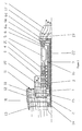
- figure 2 represents an axial section, basic drawing, through the triple flux turbojet.
- the solution contains a exterior secondary working channel 11; interior secondary working channel (8); primary working channel 9.
- the tripleflux turbojet has an exterior casing 18, profiled at the interior, which contains a secondary exterior fan 13, behind it is placed a stator 12, after that is placed a secondary stator 10 on the secondary exterior working channel 11 and on the secondary interior working channel 8 is mounted a secondary interior fan 2, after this is placed a stator 1, following on the secondary interior working channel 8 it is mounted another stator, primary stator 3, also inside the exterior casing of the primary flux 21 it is mounted a compressor 4 and behind it, bounded by the casing, is the combustion chamber equipped with injectors, after this one is a turbine 6 with three stages 6A, 6B and 6C, independent, behind the turbine is placed a nozzle.
- the primary working channel 9 is delimited by the primary flux exterior casing 21 and by the exterior casing 22.
- the secondary interior working channel 8 is delimitated by the intermediary casing 20 and by the exterior casing of the primary flux 21 which is concentric to the primary working channel 9 and the secondary exterior working channel 11 is concentric to the secondary interior working channel 8.
- the combustion chamber 5 is connected to the interior casing of the primary flux 22 and the exterior casing of the primary flux 21, this one collects the compressed air which is mixed with fuel before burning.
- the nozzle is connected to exterior casing of the primary flux 21 and to the cone 19 in the exit area through a strut 17. Consequently, in the structure of the tripleflux turbo engine, as opposed to double fan turbojet, enters the following components: secondary exterior fan 13; secondary interior fan 2.
- the structure of the fluid fluxes which participate to the realization of the system thrust, contains a primary flux, between the exterior and interior casings of the primary flux; a secondary interior flux, between intermediary and exterior casings of the secondary interior flux.
- An improvement of this engine is the presence of the secondary exterior fan 13 which offers an improvement of the thrust, 25-30 % more than the dubleflux turbojet at the same gauge. This leads also to a reduction of the specific fuel consumption with 10-15%.
- Another improvement of this engine is the exhaust nozzle which can lead to a reduction of the noise with 3-4 decibels.
- the atmospheric air flux is driven by the fan 13 and goes through the blades of the stator 12, being compressed to a bigger pressure than the atmospheric pressure.
- a part of the secondary exterior air flux which leaves the stator 12 goes into the secondary stator 10 and the rest is driven by the secondary interior fan 2 and after that goes through stator 1 where is compressed even further, after that a part passes through stator 3 and the rest enters the compressor 4.
- compressor 4 the air is compressed at a pressure necessary to combustion. Before entering the combustion chamber the compressed air is mixed with the fuel necessary for combustion.
- the resulting burned gases from combustion have high temperature and through expansion of these in the turbine it is produced the necessary work of energy to spin the compressor 4, the secondary exterior fan 13 and the secondary interior fan 2.
- the gases expand also in the nozzle 7 producing, at exit, a jet with a high speed.
- the air jet, from the secondary exterior working channel 11 and from the secondary interior working channel 8, is mixed, gradually, and the resulting air jet is mixed with the atmospheric air but also with the burned gases jet that exit from the nozzle 7, fact that leads at substantial reduction of noise produced by the tripleflux turbojet.
Landscapes
- Engineering & Computer Science (AREA)
- Chemical & Material Sciences (AREA)
- Combustion & Propulsion (AREA)
- Mechanical Engineering (AREA)
- General Engineering & Computer Science (AREA)
- Structures Of Non-Positive Displacement Pumps (AREA)
Applications Claiming Priority (1)
| Application Number | Priority Date | Filing Date | Title |
|---|---|---|---|
| RO200700304 | 2007-05-04 |
Publications (1)
| Publication Number | Publication Date |
|---|---|
| EP1988274A2 true EP1988274A2 (fr) | 2008-11-05 |
Family
ID=39537442
Family Applications (1)
| Application Number | Title | Priority Date | Filing Date |
|---|---|---|---|
| EP20080464006 Withdrawn EP1988274A2 (fr) | 2007-05-04 | 2008-04-24 | Turboréacteur |
Country Status (1)
| Country | Link |
|---|---|
| EP (1) | EP1988274A2 (fr) |
Cited By (16)
| Publication number | Priority date | Publication date | Assignee | Title |
|---|---|---|---|---|
| GB2496301A (en) * | 2011-11-01 | 2013-05-08 | United Technologies Corp | A three-spool gas turbine engine with second stream bypass flow |
| US11492918B1 (en) | 2021-09-03 | 2022-11-08 | General Electric Company | Gas turbine engine with third stream |
| US11834954B2 (en) | 2022-04-11 | 2023-12-05 | General Electric Company | Gas turbine engine with third stream |
| US12031504B2 (en) | 2022-08-02 | 2024-07-09 | General Electric Company | Gas turbine engine with third stream |
| US12044194B2 (en) * | 2019-10-15 | 2024-07-23 | General Electric Company | Propulsion system architecture |
| US12065989B2 (en) | 2022-04-11 | 2024-08-20 | General Electric Company | Gas turbine engine with third stream |
| US12410763B2 (en) | 2022-08-02 | 2025-09-09 | General Electric Company | Gas turbine engine with third stream |
| US12421917B2 (en) | 2022-08-02 | 2025-09-23 | General Electric Company | Gas turbine engine with third stream |
| US12486817B2 (en) | 2022-08-02 | 2025-12-02 | General Electric Company | Gas turbine engine with third stream |
| US12516647B2 (en) | 2022-08-02 | 2026-01-06 | General Electric Company | Gas turbine engine with third stream |
| US12560132B2 (en) | 2022-08-02 | 2026-02-24 | General Electric Company | Gas turbine engine with third stream |
| US12565866B2 (en) | 2022-08-02 | 2026-03-03 | General Electric Company | Gas turbine engine with third stream |
| US12571358B2 (en) | 2022-08-02 | 2026-03-10 | General Electric Company | Gas turbine engine with third stream |
| US12577925B2 (en) | 2022-08-02 | 2026-03-17 | General Electric Company | Gas turbine engine with third stream |
| US12577926B2 (en) | 2022-08-02 | 2026-03-17 | General Electric Company | Gas turbine engine |
| US12618384B2 (en) | 2025-01-10 | 2026-05-05 | General Electric Company | Gas turbine engine having a bypass passage, a fan duct, and a core duct |
Citations (1)
| Publication number | Priority date | Publication date | Assignee | Title |
|---|---|---|---|---|
| CA887935A (en) | 1971-12-14 | General Electric Company | Turbofan engines |
-
2008
- 2008-04-24 EP EP20080464006 patent/EP1988274A2/fr not_active Withdrawn
Patent Citations (1)
| Publication number | Priority date | Publication date | Assignee | Title |
|---|---|---|---|---|
| CA887935A (en) | 1971-12-14 | General Electric Company | Turbofan engines |
Cited By (22)
| Publication number | Priority date | Publication date | Assignee | Title |
|---|---|---|---|---|
| GB2496301B (en) * | 2011-11-01 | 2014-10-22 | United Technologies Corp | Gas turbine engine with three spool fan and flow control mechanism |
| US9279388B2 (en) | 2011-11-01 | 2016-03-08 | United Technologies Corporation | Gas turbine engine with two-spool fan and variable vane turbine |
| US10378454B2 (en) | 2011-11-01 | 2019-08-13 | United Technologies Corporation | Gas turbine engine with two-spool fan and variable vane turbine |
| GB2496301A (en) * | 2011-11-01 | 2013-05-08 | United Technologies Corp | A three-spool gas turbine engine with second stream bypass flow |
| US12044194B2 (en) * | 2019-10-15 | 2024-07-23 | General Electric Company | Propulsion system architecture |
| US20240344487A1 (en) * | 2019-10-15 | 2024-10-17 | General Electric Company | Propulsion system architecture |
| US11492918B1 (en) | 2021-09-03 | 2022-11-08 | General Electric Company | Gas turbine engine with third stream |
| US11859516B2 (en) | 2021-09-03 | 2024-01-02 | General Electric Company | Gas turbine engine with third stream |
| US11834954B2 (en) | 2022-04-11 | 2023-12-05 | General Electric Company | Gas turbine engine with third stream |
| US12065989B2 (en) | 2022-04-11 | 2024-08-20 | General Electric Company | Gas turbine engine with third stream |
| US12523188B2 (en) | 2022-08-02 | 2026-01-13 | General Electric Company | Gas turbine engine with third stream |
| US12410763B2 (en) | 2022-08-02 | 2025-09-09 | General Electric Company | Gas turbine engine with third stream |
| US12421917B2 (en) | 2022-08-02 | 2025-09-23 | General Electric Company | Gas turbine engine with third stream |
| US12486817B2 (en) | 2022-08-02 | 2025-12-02 | General Electric Company | Gas turbine engine with third stream |
| US12516647B2 (en) | 2022-08-02 | 2026-01-06 | General Electric Company | Gas turbine engine with third stream |
| US12031504B2 (en) | 2022-08-02 | 2024-07-09 | General Electric Company | Gas turbine engine with third stream |
| US12560132B2 (en) | 2022-08-02 | 2026-02-24 | General Electric Company | Gas turbine engine with third stream |
| US12565866B2 (en) | 2022-08-02 | 2026-03-03 | General Electric Company | Gas turbine engine with third stream |
| US12571358B2 (en) | 2022-08-02 | 2026-03-10 | General Electric Company | Gas turbine engine with third stream |
| US12577925B2 (en) | 2022-08-02 | 2026-03-17 | General Electric Company | Gas turbine engine with third stream |
| US12577926B2 (en) | 2022-08-02 | 2026-03-17 | General Electric Company | Gas turbine engine |
| US12618384B2 (en) | 2025-01-10 | 2026-05-05 | General Electric Company | Gas turbine engine having a bypass passage, a fan duct, and a core duct |
Similar Documents
| Publication | Publication Date | Title |
|---|---|---|
| EP1988274A2 (fr) | Turboréacteur | |
| US11047339B2 (en) | Gas turbine engine with optimized fan, core passage inlet, and compressor forward stage diameter ratios | |
| EP3339607B1 (fr) | Architecture de moteur à écoulement inverse | |
| US7334392B2 (en) | Counter-rotating gas turbine engine and method of assembling same | |
| CN101021181B (zh) | 双旁路涡轮风扇发动机 | |
| US10352274B2 (en) | Direct drive aft fan engine | |
| CN106150701B (zh) | 用于支承间接驱动的涡扇发动机的转子轴的系统 | |
| US20070125066A1 (en) | Turbofan engine assembly and method of assembling same | |
| CN107191271A (zh) | 具有涡轮压缩机的发动机引气系统 | |
| US10920713B2 (en) | Compression cowl for jet engine exhaust | |
| EP1637711A3 (fr) | Turbine à gaz à haute poussé avec générateur de gaz modifié | |
| EP3239511A1 (fr) | Ensemble de turboréacteur et procédé d'assemblage | |
| CN107916995A (zh) | 燃气涡轮发动机 | |
| US20180216576A1 (en) | Supersonic turbofan engine | |
| US9752585B2 (en) | Gas turbine engine architecture with intercooled twin centrifugal compressor | |
| US6962479B2 (en) | Compound centrifugal and screw compressor | |
| CN115199406B (zh) | 具有嵌入式电机的三流燃气涡轮发动机 | |
| CN108506111B (zh) | 一种微小型涡扇发动机 | |
| CA2964988C (fr) | Systeme et methode d'influence du flux dans un ventilateur d'une turbine a gaz | |
| CN212272644U (zh) | 用于飞行器的气体涡轮引擎和飞行器 | |
| CN113006940B (zh) | 一种无需外部减速器的微小型涡桨发动机 | |
| CN106368851A (zh) | 一种多风扇推进装置 | |
| CN111608953A (zh) | 用于气体涡轮引擎的冰晶体防护 | |
| EP3536902A1 (fr) | Composant de moteur à turbine à gaz | |
| CN111878257B (zh) | 涡轮引擎 |
Legal Events
| Date | Code | Title | Description |
|---|---|---|---|
| PUAI | Public reference made under article 153(3) epc to a published international application that has entered the european phase |
Free format text: ORIGINAL CODE: 0009012 |
|
| 17P | Request for examination filed |
Effective date: 20080424 |
|
| AK | Designated contracting states |
Kind code of ref document: A2 Designated state(s): AT BE BG CH CY CZ DE DK EE ES FI FR GB GR HR HU IE IS IT LI LT LU LV MC MT NL NO PL PT RO SE SI SK TR |
|
| AX | Request for extension of the european patent |
Extension state: AL BA MK RS |
|
| STAA | Information on the status of an ep patent application or granted ep patent |
Free format text: STATUS: THE APPLICATION IS DEEMED TO BE WITHDRAWN |
|
| 18D | Application deemed to be withdrawn |
Effective date: 20101103 |