EP1988627A2 - Contrôle de machine électrique sans balai - Google Patents
Contrôle de machine électrique sans balai Download PDFInfo
- Publication number
- EP1988627A2 EP1988627A2 EP08005974A EP08005974A EP1988627A2 EP 1988627 A2 EP1988627 A2 EP 1988627A2 EP 08005974 A EP08005974 A EP 08005974A EP 08005974 A EP08005974 A EP 08005974A EP 1988627 A2 EP1988627 A2 EP 1988627A2
- Authority
- EP
- European Patent Office
- Prior art keywords
- flux
- signal
- controller
- phase winding
- stabilisation
- Prior art date
- Legal status (The legal status is an assumption and is not a legal conclusion. Google has not performed a legal analysis and makes no representation as to the accuracy of the status listed.)
- Granted
Links
Images


Classifications
-
- H—ELECTRICITY
- H02—GENERATION; CONVERSION OR DISTRIBUTION OF ELECTRIC POWER
- H02P—CONTROL OR REGULATION OF ELECTRIC MOTORS, ELECTRIC GENERATORS OR DYNAMO-ELECTRIC CONVERTERS; CONTROLLING TRANSFORMERS, REACTORS OR CHOKE COILS
- H02P25/00—Arrangements or methods for the control of AC motors characterised by the kind of AC motor or by structural details
- H02P25/02—Arrangements or methods for the control of AC motors characterised by the kind of AC motor or by structural details characterised by the kind of motor
- H02P25/08—Reluctance motors
-
- H—ELECTRICITY
- H02—GENERATION; CONVERSION OR DISTRIBUTION OF ELECTRIC POWER
- H02P—CONTROL OR REGULATION OF ELECTRIC MOTORS, ELECTRIC GENERATORS OR DYNAMO-ELECTRIC CONVERTERS; CONTROLLING TRANSFORMERS, REACTORS OR CHOKE COILS
- H02P6/00—Arrangements for controlling synchronous motors or other dynamo-electric motors using electronic commutation dependent on the rotor position; Electronic commutators therefor
- H02P6/14—Electronic commutators
- H02P6/15—Controlling commutation time
-
- Y—GENERAL TAGGING OF NEW TECHNOLOGICAL DEVELOPMENTS; GENERAL TAGGING OF CROSS-SECTIONAL TECHNOLOGIES SPANNING OVER SEVERAL SECTIONS OF THE IPC; TECHNICAL SUBJECTS COVERED BY FORMER USPC CROSS-REFERENCE ART COLLECTIONS [XRACs] AND DIGESTS
- Y10—TECHNICAL SUBJECTS COVERED BY FORMER USPC
- Y10S—TECHNICAL SUBJECTS COVERED BY FORMER USPC CROSS-REFERENCE ART COLLECTIONS [XRACs] AND DIGESTS
- Y10S388/00—Electricity: motor control systems
- Y10S388/907—Specific control circuit element or device
- Y10S388/915—Sawtooth or ramp waveform generator
Definitions
- This invention relates to the control of switched brushless electrical machines.
- the invention particularly, but not exclusively, relates to switched reluctance machines.
- the switched reluctance machine is a type of brushless electrical machine. It comprises a rotor, defining rotor poles, a stator, defining stator poles, and a set of windings arranged in relation to the stator poles to define one or more independently energisable phases.
- energisation of one or more phase windings sets up magnetic flux in a circuit which includes the associated stator poles, urging the rotor into a position of minimum reluctance. Timing the sequential energisation of the windings according to rotor position induces rotor movement.
- a general treatment of electrical drives which incorporate switched reluctance machines can be found in various textbooks, e.g.
- switched reluctance machines are purely 'magnetic' machines.
- the torque is produced solely by the magnetic field as the reluctance of the magnetic circuit changes. It follows that the methods of controlling the two types of machine are quite different, since the control is related to the method of torque production. In general, the control methods used for sinusoidally fed conventional machines are inappropriate for switched reluctance machines.
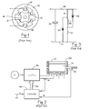
- FIG. 1 shows a typical switched reluctance machine in cross section.
- the magnetisable stator 10 has six stator poles 12.
- the magnetisable rotor 14 has four rotor poles 16.
- Each stator pole carries a coil 18.
- the coils on diametrically opposite poles are connected in series to provide three phase windings. Only one phase winding is shown, for clarity.
- the control of the switched reluctance machine can be achieved in a variety of ways well known to the person skilled in the art. If information on the angular position of the rotor is available, e.g. from a position transducer, the excitation can be applied as a function of the position. Such machines are often referred to as "rotor position switched machines”.
- a typical switched reluctance drive is shown in Figure 2 .
- the machine 36 corresponds to that shown in Figure 1 .
- the three phase windings, A, B and C are switched in turn onto a DC supply V by a set of power electronic switches 48.
- the moments (i.e., the rotor positions) at which the switches operate are determined by the controller 38, which may be implemented either in hardware or in the software of a processing device such as a microcontroller or digital signal processor.
- the control signals are sent to the switches via a data bus 46. Closed loop current feedback is provided by sensing the phase currents using a current sensor 44 and feeding back a signal proportional to phase current which is compared to a demanded current i D .
- the control algorithms often include a proportional (P), proportional-plus-integral (P+I), time optimal, feedback linearised, proportional/integral/ derivative (PID) function, or one of many others as is well understood in the art. It is also common for an outer control loop of position or speed to be provided by feeding back a rotor position signal from a position detector 40.
- P proportional
- P+I proportional-plus-integral
- PID proportional/integral/ derivative
- a signal corresponding to current demand 42 is provided to the controller. This regulates the current in the windings, according to the particular control scheme adopted, to produce the desired output from the machine.
- the performance of a switched reluctance machine depends, in part, on the accurate timing of phase energisation with respect to rotor position.
- Detection of rotor position is conventionally achieved by using a physical rotor position transducer (RPT) 40, shown schematically in Figure 2 , such as a rotating toothed disk mounted on the machine rotor, which co-operates, for example, with an optical or magnetic sensor mounted on the stator.
- RPT physical rotor position transducer
- a pulse train indicative of rotor position relative to the stator is generated and supplied to the processing device, allowing accurate phase energisation.
- Alternative methods of position detection include the so-called "sensorless" methods, in which there is no physical position transducer and the position is deduced from measurements of one or more other parameters of the machine.
- the capacitor 25 may comprise several capacitors connected in series and/or parallel. Where parallel connection is used, some of the elements may be distributed throughout the converter.
- a polyphase system typically uses several "phase legs" of Figure 3 connected in parallel to energise the phases of the electrical machine independently.
- the phase inductance cycle of a switched reluctance machine is the period of the variation of inductance for the, or each, phase between common points in successive cycles (for example between inductance maxima when the rotor poles and the relevant respective stator poles are fully aligned).
- the maximum inductance region, L max is centred around the rotor position where a pair of rotor poles are fully aligned with a pair of stator poles.
- the minimum inductance region, L min corresponds to the position where the interpolar axis on the rotor is aligned with the stator pole axis, as shown in Figure 1 .
- switched reluctance systems generally operate in a current-controlled or "chopping" mode.
- a hysteresis current controller using “hard” chopping is often used, as explained in the Stephenson paper referred to above.
- An alternative regime is “soft” chopping in which only one switch is opened when the current reaches its upper level. The current then decays much more slowly through the winding, the second switch and one diode.
- Other types of current controllers are well known in the art, for example those described in EP-A-0769844 , which is incorporated herein by reference, off-time controllers, constant frequency controllers, etc., and will not be further described here.
- switched reluctance systems typically operate in the "single-pulse" mode of energisation instead of the chopping mode. This is also explained in the Stephenson paper referred to above.
- systems generally use a chopping mode at low speeds and a single-pulse mode at higher speeds.
- the upper and lower chopping current levels are normally set to values above the expected peak current of the single pulse mode, so that these parameters do not interfere with single-pulse operation. It is known to set the upper current level to a value which would act as a "safety net" so that if a fault condition developed in the drive, the current would exceed this upper level and cause one or more switching devices to be opened, thereby limiting the current to a safe value.
- a further mode of operation is the so-called “continuous current” mode, which makes it possible to produce mechanical output torques and powers greatly in excess of that obtained up to the "limiting condition" in the single pulse mode.
- It is disclosed in US Patent No. 5469039 (Stephenson ), and incorporated herein by reference.
- This patent discloses a method of operating in a stable manner in this mode so that steady state operation is possible.
- the phase windings therefore operate with current continuously flowing through them, unlike in the chopping and single pulse modes, and are always linked by flux.
- the current variation is quasi-sinusoidal above a "standing” value. This has become an important mode for systems which have to produce high levels of overload output at some points of their operating cycle.
- VA volt-ampere
- the parameters of angles and currents for controlling the machine in the different modes are generally functions of speed and are either computed in real time or, more commonly, stored in some form of data table from which they can be read at appropriate times.
- the parameter values are carefully chosen in order to achieve smooth output from the machine as the speed changes. If the stored values are relatively sparse, some form of interpolation is used to give suitable parameter values at intermediate speeds. There is a particular difficulty in choosing values at the transition points between chopping and single-pulse modes, and between single-pulse and continuous current modes, where a smooth transition is desired regardless of the torque level demanded.
- the current control parameters are generally held constant with speed for a given torque demand throughout the chopping range.
- the current control parameters are generally set to a high value so that they do not cause chopping for the rest of the single-pulse speed range.
- a major difficulty remains, however.
- the use of current control to regulate torque in the continuous current mode does not address the difficulty of achieving a smooth transition into and out of the mode.
- the exact point at which the onset of continuous current occurs will be depend not only on winding temperature, but will also be sensitive to the supply voltage and to variations from one particular machine sample to another.
- a single control parameter "map" can effect a smooth transition only at one supply voltage and winding temperature; the difficulties of compensating for both voltage and winding temperature will be self-evident, especially when considering the high sensitivity of machine output to parameter variations whilst operating in the continuous current mode.
- a controller for a brushless electrical machine having at least one phase winding comprising control means operable to produce a control signal for energisation of the phase winding in response to an input signal, and being operable to modify the input signal using a flux stabilisation signal, thereby altering the flux produced by the phase winding to stabilise the output of the machine.
- control means operable to produce a control signal for energisation of the phase winding in response to an input signal, and being operable to modify the input signal using a flux stabilisation signal, thereby altering the flux produced by the phase winding to stabilise the output of the machine.
- the flux stabilisation signal is used to influence the moment at which the flux decay in a machine phase winding is initiated by modifying the input signal to the control means according to the moment at which the flux in the phase is arranged to decay.
- the flux stabilisation signal has a sawtooth waveform typically with a linear gradient. This can have a negative slope and is combined with a flux demand signal and compared with a flux feedback signal which is indicative of the instantaneous flux in the machine itself.
- the sawtooth waveform of the flux stabilisation signal can have a positive slope and is combined with the flux feedback signal instead. This combined signal is compared with the flux demand signal.
- the effect of the stabilisation signal is to cause a transition from rising flux to falling flux. Even in the presence of any disturbance there is an adequate period (both angular and temporal) for the flux to be stably controlled before the end of the period of energisation of the phase.
- the stability signal is adapted to maintain the rise and fall of flux to be substantially equal over the electrical cycle.
- the combination of the flux stabilisation signal and the flux feedback signal or flux demand signal can be derived by adding them together in an adder.
- the controller may include means for generating the flux stabilisation signal as a time variable signal which has a period that is coincident with the period of repetition of energisation of the phase winding.
- the gradient of the sawtooth waveform of the stabilisation signal can vary with the speed of the machine.
- the gradient can be increased as the speed increases and the period of time of the electrical cycle is shortened.
- the peak amplitude of the sawtooth waveform may remain the same regardless of machine speed.
- the stabilisation signal is used to modify a signal indicative of flux growth in the phase winding.
- the rate of growth of flux as indicated by a flux feedback signal, is modified such that the apparent rate of flux growth increases.
- the input signal is modified thereby enabling the switch-off point to be determined.
- a controller for a switched reluctance machine having a rotor, a stator with at least one phase winding and switch means for energising the at least one phase winding, the controller being operable to generate actuation signals for actuating the switch means, the controller including first switch control means for producing switch-off signals for controlling the switch means when the flux in the at least one phase winding exceeds a flux demand signal and second switch control means for producing actuation signals for controlling the switch means according to the position of the rotor relative to the stator.
- This controller may comprise a comparator arranged to receive a first flux signal indicative of the flux in the at least one phase winding and a second flux signal indicative of the demanded flux, and to produce a switch-off signal when the first flux signal exceeds the second flux signal.
- the second switch control means may be operable to produce a switch-on signal when the rotor reaches a predetermined position relative to the stator, whereby the flux in the phase winding is increased.
- the second switch control means may also be operable to produce a freewheel signal for freewheeling the current in the at least one phase winding when the rotor reaches a freewheel position relative to the stator, whereby flux in the phase winding is allowed to decay.
- the second switch control means may also be operable to produce a switch-off signal when the rotor reaches a switch-off position relative to the stator, whereby the flux in the phase winding is driven down.
- the invention can be applied to various brushless electrical machines, such as switched reluctance machines or brushless DC machines.
- a first embodiment of a switched reluctance drive system includes a switched reluctance machine 36 having a laminated magnetisable stator 10, carrying phase windings A,B,C, and a laminated magnetisable rotor 14. Each is constructed in this embodiment of laminations of a suitable steel known to the person of ordinary skill in the art.
- a rotor position transducer (RPT) 40 is arranged in relation to the rotor 14 to monitor position.
- the RPT can take various forms in which the movement of a first element past a sensing device causes an output indicative of relative movement of the rotor relative to the stator.
- a flux controller 90 produces control signals for actuating power electronic switches 48 configured, for example, in phase legs as shown in Figure 3 , for controlling the energisation of the phase windings A, B and C associated with the stator 10.
- the schematically illustrated connection of only one phase winding is shown for the sake of clarity, but each phase is independently energisable by actuation of the switches.
- the energisation for the windings is provided by an amplifier of known type.
- the flux controller 90 is provided with three feedback signals. Firstly, it receives rotor position signals ⁇ from the RPT 40. In alternative embodiments, the rotor position signals are provided by an algorithm which deduces the rotor position from other parameters of the machine. In either case, the signal ⁇ provides positional (and hence timing) information to the flux controller 90. Secondly, the flux controller 90 receives phase current signals i from a current transducer 44. It will be appreciated that each phase winding will typically have associated with it a current transducer 44 to produce the current signals i, but only one transducer is shown here for the sake of clarity.
- the current feedback signal is not used in the manner of a conventional current controller: rather, it is used to provide overall monitoring of current to ensure that it stays within a predetermined safe level.
- the flux controller 90 receives flux signals ⁇ proportional to the flux in each phase winding. These signals are derived either by direct measurement of the flux or by one of the several methods of flux estimation known to the person of ordinary skill in the art.
- the input 92 to the flux controller 90 is a demand signal representing the desired peak flux ⁇ D in the machine to produce a desired output.
- the desired output is torque, speed or position.
- the desired output is typically electrical power.
- the flux controller 90 has a further flux stabilisation input 94, which is described in more detail below.
- the flux controller 90 produces control signals, which are passed through the data bus 46 to the power electronic switches 48 that control energisation of the phase windings from the voltage source V.
- the flux-related inputs provide a means of terminating a phase voltage pulse should the phase flux reach a limiting value before the rotor reaches the end of the conduction period at which the phase switches would normally be opened in a single-pulse mode, or before the phase current reaches a predetermined value in a chopping mode.
- Figure 5 shows the waveforms for the machine operating in continuous current mode.
- the demanded peak flux level ⁇ D reduces the anticipated conduction angle ⁇ c , so that the flux cycles between the values of ⁇ D and a standing value ⁇ S .
- the value ⁇ S is not directly controlled but arises naturally as a consequence of the demanded peak flux ⁇ D , the machine speed and the rate of rise and fall of the flux (which in turn is determined by the supply voltage and the number of turns in the phase winding).
- FIG. 6 An exemplary embodiment of a commutator for an SR machine which overcomes the problems outlined above is shown in Figure 6 .
- This forms part of the controller 90 in Figure 4 producing the switch control outputs on bus 46.
- the output ⁇ from the RPT 40 (see Figure 4 ) is compared with the predetermined values of angle for switch-on ⁇ on , freewheel ⁇ fw and switch-off ⁇ off in respective comparators 100, 102 and 104.
- the flux feedback signal ⁇ (which may be a derivation of direct feedback or an estimate of flux) is compared with the demanded flux ⁇ D in a further comparator 106.
- the output of the flux comparator 106 together with the output of the switch-off comparator 104 are applied to an OR gate 108.
- the output of the flux comparator 106 together with the output of the freewheel comparator 102 are applied to an OR gate 110.
- the output of the switch-on comparator 100 provides the SET input to a first set/reset (SR) latch 120.
- the RESET input to the first latch 120 is the output of the OR gate 110.
- the output of the switch-on comparator 100 also provides the SET input to a second set/reset (SR) latch 122.
- the RESET input to the second latch 122 is the output of the OR Gate 108.
- the outputs from the latches are the inputs to a controller 124 which monitors the current in the phase winding level and derives the control signals for bus 46 to supply to the power electronic switches 48 in Figure 4 .
- the controller is part of the flux controller 90. As such it is either constituted by a sub-routine in a single processing device or is a separate processing device. In either case it is, for example, a microprocessor or a digital signal processor running software to execute the recognised steps for implementing the control technique described herein.
- the controller includes features which monitor the current and take appropriate action if the current exceeds predetermined thresholds.
- the circuit of Figure 6 can be operated as follows. When the rotor angle ⁇ reaches switch-on angle ⁇ on both the SR latches 120, 122 are "set”. This activates the phase switching devices (subject to the overall consent of the subsequent controller 124). After the start of conduction at ⁇ on , the phase flux ⁇ builds from ⁇ S , with an approximately linear rise of flux with time. If the rotor position estimate (or measurement) reaches the freewheel angle ⁇ fw or the turn-off angle ⁇ off before the phase flux reaches the limiting value ⁇ D , the output of comparator 102 or 104 changes state.
- One or both SR latches are then cleared or "reset” by an output from one or both OR gates 108 and 110 to the R inputs to the latches 120/122.
- the phase current and flux will then decay slowly (if the freewheel angle has been reached and only one of the switches 21/22 has been opened) or rapidly (if the off-angle has been reached and both switches are opened).
- the values of ⁇ on , ⁇ off and ⁇ fw are set as thresholds, either calculated in real time or stored in a memory of some known form. This is angle-based commutation.
- phase flux may reach the flux limit ⁇ D before the off-angle is reached.
- both latches will be reset immediately, so forcing down the phase flux regardless of the anticipated conduction angle.
- the machine is now being controlled as a function of its peak flux.
- An alternative scheme opens just one of the phase switches 21/22 when the flux limit is reached - this would initiate freewheeling, and the phase flux would then fall only slowly until the off-angle is reached.
- the system of Figure 6 is able to operate in either of the single pulse or continuous current modes according to the inputs to the comparators 100-106.
- the system can operate as a conventional chopping current controller, an angle controller or a peak flux controller. All these modes of operation of the controller 90 are beneficial because, particularly in the continuous current mode, the torque produced is smoothly and progressively controlled by ⁇ D and is not sensitive to winding resistance, supply voltage or the exact value of the control angles. It also provides a means for a smooth and continuous transition between the single-pulse and continuous current modes even when there are variations in the operating conditions of the machine.
- optimal operation of the controller described above relies on the absence of disturbances in the input and feedback parameters to which operation in the continuous current mode is particularly prone.
- Such disturbances can arise from a number of sources.
- electrical noise may be present in, for example, the current or flux measurement.
- the rotor In a drive with low inertia, the rotor may be changing speed or direction quickly.
- the estimates may suffer from random errors, leading to jitter in the control angles being supplied to the controller.
- Drives which use digital circuitry in the control system may suffer from quantisation effects. Any, or a combination, of these factors may lead to instability in the flux controller.
- FIG. 7 An example of such instability is shown in Figure 7 .
- a transient disturbance ⁇ occurs in ⁇ D during the second cycle, causing an early termination of the rising flux.
- the flux demand is restored to its intended value, the subsequent cycles of flux become unstable, leading to erratic output of the machine.
- very small values of disturbance are sufficient to cause instability, since the error introduced by the disturbance will not decay of its own accord.
- the gradients of the (linearised) flux waveform are designated m u and m d respectively as shown in Figure 7 .
- the units of the gradients are Webers/degree or, if the diagram were drawn in the time domain, Webers/sec. The units are interchangeable because the machine is taken to be rotating at constant speed.
- the numerical value of m u is positive and that of m d is negative.
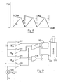
- a stabilisation signal in the form of a negative-going ramp, synchronised to the period of the rpt signal, as shown in Figure 8 .
- the gradient of the ramp m stab also has units of Weber/degree in the angle domain and its numerical value is negative. It can be shown, by linear algebra, that the error in the waveform will decay to zero provided that m u - m stab > m d i.e., m u - m stab + m d > 0
- Figure 9 shows how this may be implemented in the flux controller of Figure 6 and like reference numerals have been used for like parts.
- the controller 124 of Figure 9 has the inputs to the flux controller 90 in Figure 4 .
- the flux demand signal ⁇ D is supplied to an adder 126 where it is combined with the flux stabilisation signal ⁇ stab which is in the form of the negative-going saw-tooth waveform shown in Figure 8 and which repeats coincident with each conduction cycle.
- the effect of combining the two signals is to give a peak flux demand which is time (i.e., rotor position) dependent and now automatically takes into account the effects of signal disturbances and/or parameter variations which otherwise alter the balance between the rising and falling parts of the flux waveform in each electrical cycle.
- the addition of this flux stabilising signal produces a stable system.
- the flux stabilisation signal ⁇ stab could equivalently be applied to the other terminal of the flux comparator 106, i.e. added to the flux feedback instead of to the demand reference.
- a positive-going ramp for the flux stabilisation waveform m stab would be required to achieve the same effect.
- Other combinations using a combination of a suitable ramp waveform (negative or positive-going) are of course possible, again with equivalent results.
- the flux stabilisation signal is referred to above as a linear sawtooth waveform, other forms of flux stabilisation signal are possible within each electrical cycle.
- the gradient of the flux stabilisation signal may equally well be exponential or some other non-linear function. The choice of the waveform will depend on the application.
- the resistive and semi-conductor voltage drops will typically be relatively small compared with the DC link voltage.
- the gradient m d of the flux will be only very slightly steeper than the gradient m u of the flux due to the high value of the voltage (which is the determining factor in the rate of flux change per unit time).
- the combined gradient (m u - m stab ) is steeper than that of m d . In effect, this causes the rate of rise of measured flux to be greater than the fall.
- the result of adding the flux stabilisation signal is to cause the measured flux to reach its threshold relatively early, thereby leaving time for the decaying flux to fall sufficiently.
- the influence of the flux stabilisation signal is to maintain the rise and fall of flux produced by the phase winding over an electrical cycle to be substantially equal by ensuring that any error introduced into the waveforms will decay cycle by cycle.
- the degree of stabilisation required for a given machine is not directly tied to the level of flux demanded unless the machine's per-unit resistance is high, thereby causing a larger difference between m u and m d .
- the low resistance of typical machines means the gradients m u and m d will each vary by only small amounts as the load on the machine increases so that effectively the gradients m u and m d will be substantially constant regardless of load.
- ripple in the dc link voltage may, in some cases, introduce an uncertainty that needs to be addressed by the stabilisation, i.e. the stabilisation needs to be increased to cater for perturbations in m u and m d due to ripple.
- the stabilisation needs an amplitude sufficient to boost the apparent rate of rise of flux by the difference between these two figures, namely 0.32 Webers per second.
- the most difficult area for stabilisation occurs at maximum phase current where the ohmic voltage drop across the winding is at its greatest and the resultant flux waveform becomes non-linear.
- the ideal solution for a non-linear flux rise and fall is to have a stabilisation curve that still has a period coincident with the period of repetition of energisation of the phase winding (as above) but has a non-linear profile suited to the flux waveforms. This can be implemented if required, at the expense of more complex circuitry and/or algorithms.
- the nature of the flux stabilisation signal may vary dynamically as operating conditions for the machine change. It should also be noted that the flux control scheme discussed above, whilst particularly advantageous for the control of the continuous current mode, is not constrained to use solely in that mode: it is equally applicable to discontinuous flux operation at lower torques and speeds. When it is employed for control of the continuous current mode, it has been found beneficial to bring the flux limit into play progressively before the onset of the continuous current mode, so that there is a seamless transition between discontinuous and continuous current/flux modes.
- the disclosed embodiment uses a flux stabilisation signal which is cyclical coincident with the conduction cycle of the machine.
- the flux waveform is superimposed on the value of the flux demand signal or the measured flux signal so that the effective value at which the flux growth in a phase changes to falling flux falls over the phase condition cycle.
- any disturbance in the system which would otherwise give rise to progressive flux growth or erratic output is compensated by the changing value at which rising flux changes to falling flux such that an adequate part of the conduction cycle (and therefore a greater period of time) is available for the flux to be stably controlled by actuation of the switches.
- FIG. 8 and 9 makes use of a continuously available measurement or estimate of flux. In many systems which are operating with sensorless position detection, this signal is already present and so can be used for the further purpose of flux stabilisation. If, however, the system is deriving position information from a physical position transducer as described above, a flux signal may not be available and would need to be generated specifically for flux stabilisation. Typically, this would be done by integrating the phase voltage, which requires significant processing capability to yield a reliable signal.
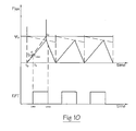
- FIG 10 Another embodiment is shown in Figure 10 as would be implemented in the controller 90 of Figure 4 when arranged to control the machine 10 according to signals from a physical rotor position transducer. This avoids the need for continuous flux information with a consequent reduction in the required processing power.
- this embodiment provides a snapshot of the flux at a particular moment and then extrapolates to find the appropriate turn-off time.
- a signal from a rotor position transducer (or some functional equivalent) is available to allow the phase winding to be energised at t o .
- the current can be recorded and its value stored, the value being zero if the machine is in single-pulse mode and non-zero if the machine is in the continuous current mode. From a knowledge of this current and the turn-on point t o , the flux can be determined from the magnetic characteristics of the machine. This value of flux is stored.
- a timer is set to run from to and the sequence of steps as would be carried out according to this embodiment are shown in Figure 11 .
- any other predetermined position of the rotor could be used to equal effect.
- an RPT output may not actually be coincident with an event such as L min . This would still be a convenient predetermined position rotor position for the purposes of this invention.
- Figure 10 shows this method superimposed on the method shown in Figure 8 and demonstrates the equivalence of the two embodiments.
- the stabilisation term is added to the calculated flux, rather than subtracted from the flux demand signal.
- the benefit of this embodiment is the elimination of the need for a continuous integration of the applied phase voltage to produce a flux estimate. Only one timer together with simple storage and calculation processes are required.
- FIG 11 shows an exemplary flowchart to implement the processes of this embodiment. It will be appreciated that, unless otherwise stated, the process is performed in the suitably programmed controller like that labelled 90 in Figure 4 to which signals from a hardware rotor position transducer (RPT) are supplied in an essentially conventional manner.
- the process starts at step 110 by testing to see if the phase energisation point to has been reached according to the signals from the RPT. If not, control loops around to the start of the process. If it has, step 112 samples the current already in the phase, if any, using a current transducer 44 as shown in Figure 4 . That value, and the rotor angle corresponding to to, is then used to evaluate the flux.
- RPT hardware rotor position transducer
- a timer function in the controller is started and the phase is energised by connecting it to the voltage supply by the switches in the power converter 48.
- a test is set up to determine when the rotor position transducer (or equivalent) signals that the minimum inductance position L min has been reached. When it has, the current is again sampled and stored and the flux evaluated at step 114. The flux stabilisation term is also added to the calculated flux to give the value of flux f 1 .
- Step 115 takes the value of flux at to and the value f 1 and extrapolates according to the chosen extrapolation method to find the time t 2 at which the flux is expected to reach the demanded flux level.
- the timer continues to run and step 116 determines when the timer reaches t 2 .
- Step 117 switches off the phase so that the flux, and hence current, decay towards zero. Control is looped around to begin the next cycle at 118.
- the invention in its various embodiments provides a flux control technique for electronically switched brushless machines of various types, and is particularly suited to switched reluctance machines. It produces a real-time signal of the flux in the magnetic circuit of the machine with which a reference value of flux can be compared to control the machine output in a stable manner in the presence of electrical noise and other disturbances.
- the disclosed embodiments illustrate a significant benefit, in that the additional control scheme can be incorporated into an existing SR control system with minimal modification, and without having to re-define existing sets of control data, which remain valid outside of the continuous current mode.
Landscapes
- Engineering & Computer Science (AREA)
- Power Engineering (AREA)
- Control Of Motors That Do Not Use Commutators (AREA)
- Control Of Electric Motors In General (AREA)
- Control Of Ac Motors In General (AREA)
Applications Claiming Priority (1)
| Application Number | Priority Date | Filing Date | Title |
|---|---|---|---|
| GBGB0708739.8A GB0708739D0 (en) | 2007-05-04 | 2007-05-04 | Control of a brushless electrical machine |
Publications (3)
| Publication Number | Publication Date |
|---|---|
| EP1988627A2 true EP1988627A2 (fr) | 2008-11-05 |
| EP1988627A3 EP1988627A3 (fr) | 2015-08-19 |
| EP1988627B1 EP1988627B1 (fr) | 2018-10-24 |
Family
ID=38198819
Family Applications (1)
| Application Number | Title | Priority Date | Filing Date |
|---|---|---|---|
| EP08005974.4A Not-in-force EP1988627B1 (fr) | 2007-05-04 | 2008-03-28 | Contrôle de machine électrique sans balai |
Country Status (5)
| Country | Link |
|---|---|
| US (1) | US7880415B2 (fr) |
| EP (1) | EP1988627B1 (fr) |
| KR (1) | KR101537780B1 (fr) |
| CN (1) | CN101299583B (fr) |
| GB (1) | GB0708739D0 (fr) |
Families Citing this family (18)
| Publication number | Priority date | Publication date | Assignee | Title |
|---|---|---|---|---|
| GB0804866D0 (en) * | 2008-03-17 | 2008-04-16 | Rolls Royce Plc | Electrical machine arrangement |
| GB201006398D0 (en) * | 2010-04-16 | 2010-06-02 | Dyson Technology Ltd | Control of a brushless motor |
| GB201006397D0 (en) | 2010-04-16 | 2010-06-02 | Dyson Technology Ltd | Control of a brushless motor |
| GB201006395D0 (en) | 2010-04-16 | 2010-06-02 | Dyson Technology Ltd | Control of a brushless motor |
| GB201006390D0 (en) | 2010-04-16 | 2010-06-02 | Dyson Technology Ltd | Control of a brushless motor |
| GB201006388D0 (en) | 2010-04-16 | 2010-06-02 | Dyson Technology Ltd | Control of brushless motor |
| GB201006386D0 (en) | 2010-04-16 | 2010-06-02 | Dyson Technology Ltd | Control of a brushless motor |
| GB2484289B (en) | 2010-10-04 | 2013-11-20 | Dyson Technology Ltd | Control of an electrical machine |
| US8975878B2 (en) | 2010-12-23 | 2015-03-10 | Caterpillar Inc. | Switched reluctance generator integrated controls |
| CN106341060A (zh) * | 2010-12-30 | 2017-01-18 | 达尔科技股份有限公司 | 生成用于无刷dc电机的线圈切换信号 |
| SG185835A1 (en) * | 2011-05-11 | 2012-12-28 | Creative Tech Ltd | A speaker for reproducing surround sound |
| US9722517B2 (en) * | 2014-04-01 | 2017-08-01 | Mcmaster University | Systems and methods for rotor position determination |
| CN104716874A (zh) * | 2015-02-28 | 2015-06-17 | 广东美的制冷设备有限公司 | 无刷直流电机控制系统及控制方法 |
| DE112016003132T5 (de) * | 2015-12-25 | 2018-03-29 | Komatsu Ltd. | Steuervorrichtung für eine rotierende elektrische Maschine, Arbeitsmaschine und Verfahren zur Steuerung einer rotierenden elektrischen Maschine |
| CN106712628B (zh) * | 2016-12-12 | 2019-02-19 | 山东航天电子技术研究所 | 一种无位置传感器无刷直流电机的电流闭环启动方法 |
| GB201712391D0 (en) * | 2017-08-01 | 2017-09-13 | Turner Michael James | Controller for an electromechanical transducer |
| CN107888120B (zh) * | 2017-12-04 | 2020-07-17 | 河海大学 | 悬浮力绕组锯齿波电流型的bsrm期望电流计算方法 |
| CN114301332B (zh) * | 2021-12-03 | 2025-07-04 | 珠海格力电器股份有限公司 | 电机的控制方法、控制装置、控制设备、电机和电器设备 |
Citations (5)
| Publication number | Priority date | Publication date | Assignee | Title |
|---|---|---|---|---|
| US5469039A (en) | 1991-09-25 | 1995-11-21 | Switched Reluctance Drives Limited | Control of switched reluctance machines |
| EP0769844A1 (fr) | 1995-10-18 | 1997-04-23 | Switched Reluctance Drives Limited | Circuit de commande du courant pour machine à réluctance variable |
| EP1109308A2 (fr) | 1999-12-17 | 2001-06-20 | Switched Reluctance Drives Limited | Régulation pour une machine sans balai |
| EP1109307A2 (fr) | 1999-12-17 | 2001-06-20 | Switched Reluctance Drives Limited | Régulation pour une machine sans balai |
| US6972533B2 (en) | 2002-07-22 | 2005-12-06 | Switched Reluctance Drives Limited | Control of a switched reluctance drive |
Family Cites Families (6)
| Publication number | Priority date | Publication date | Assignee | Title |
|---|---|---|---|---|
| US6078173A (en) * | 1996-04-08 | 2000-06-20 | General Electric Company | Simultaneous self test of multiple inverters in an AC motor system |
| US6731083B2 (en) * | 1998-06-02 | 2004-05-04 | Switched Reluctance Drives, Ltd. | Flux feedback control system |
| US6388417B1 (en) * | 1999-12-06 | 2002-05-14 | Macrosonix Corporation | High stability dynamic force motor |
| GB0130237D0 (en) * | 2001-12-18 | 2002-02-06 | Switched Reluctance Drives Ltd | Rotor position detection of a switched reluctance drive |
| JP4425091B2 (ja) * | 2004-08-25 | 2010-03-03 | 三洋電機株式会社 | モータの位置センサレス制御回路 |
| FR2878662B1 (fr) * | 2004-11-30 | 2007-02-23 | Renault Sas | Procede de commande pour un fonctionnement en mode courant continu d'un ensemble d'entrainement de vehicule a moteur thermique |
-
2007
- 2007-05-04 GB GBGB0708739.8A patent/GB0708739D0/en not_active Ceased
-
2008
- 2008-03-28 EP EP08005974.4A patent/EP1988627B1/fr not_active Not-in-force
- 2008-04-10 US US12/082,364 patent/US7880415B2/en not_active Expired - Fee Related
- 2008-04-11 KR KR1020080033848A patent/KR101537780B1/ko not_active Expired - Fee Related
- 2008-04-30 CN CN2008100960763A patent/CN101299583B/zh not_active Expired - Fee Related
Patent Citations (5)
| Publication number | Priority date | Publication date | Assignee | Title |
|---|---|---|---|---|
| US5469039A (en) | 1991-09-25 | 1995-11-21 | Switched Reluctance Drives Limited | Control of switched reluctance machines |
| EP0769844A1 (fr) | 1995-10-18 | 1997-04-23 | Switched Reluctance Drives Limited | Circuit de commande du courant pour machine à réluctance variable |
| EP1109308A2 (fr) | 1999-12-17 | 2001-06-20 | Switched Reluctance Drives Limited | Régulation pour une machine sans balai |
| EP1109307A2 (fr) | 1999-12-17 | 2001-06-20 | Switched Reluctance Drives Limited | Régulation pour une machine sans balai |
| US6972533B2 (en) | 2002-07-22 | 2005-12-06 | Switched Reluctance Drives Limited | Control of a switched reluctance drive |
Non-Patent Citations (2)
| Title |
|---|
| "The Characteristics, Design and Applications of Switched Reluctance Motors and Drives' by Stephenson and Blake, presented at the PCIM", 93 CONFERENCE AND EXHIBITION AT NURNBERG, GERMANY, 21 June 1993 (1993-06-21) |
| TJE MILLER: "Electronic Control of Switched Reluctance Machines", NEWNES, 2001 |
Also Published As
| Publication number | Publication date |
|---|---|
| EP1988627A3 (fr) | 2015-08-19 |
| KR20080098317A (ko) | 2008-11-07 |
| GB0708739D0 (en) | 2007-06-13 |
| KR101537780B1 (ko) | 2015-07-17 |
| US20080272721A1 (en) | 2008-11-06 |
| US7880415B2 (en) | 2011-02-01 |
| CN101299583B (zh) | 2012-08-29 |
| CN101299583A (zh) | 2008-11-05 |
| EP1988627B1 (fr) | 2018-10-24 |
Similar Documents
| Publication | Publication Date | Title |
|---|---|---|
| EP1988627B1 (fr) | Contrôle de machine électrique sans balai | |
| JP3668319B2 (ja) | 切り換えリラクタンス機械用制御システムおよび制御方法 | |
| EP1471629B1 (fr) | Détermination de la position du rotor d'un moteur à reluctance | |
| US6972533B2 (en) | Control of a switched reluctance drive | |
| EP0801464B1 (fr) | Mise en forme du courant dans des machines à réluctance variable | |
| US6639378B2 (en) | Current chopping in switched reluctance drive systems | |
| EP0119097B2 (fr) | Moteurs pas à pas et circuits d'entraînement | |
| US6014003A (en) | Method and apparatus for controlling a switched reluctance machine | |
| Bass et al. | Robust torque control of switched-reluctance motors without a shaft-position sensor | |
| EP1139560B1 (fr) | Détection de position pour une machine à reluctance commutée | |
| US5166591A (en) | Current chopping strategy for generating action in switched reluctance machines | |
| KR102522435B1 (ko) | 하이 로터 폴 스위치드 릴럭턴스 모터의 제조 감응형 제어 | |
| EP1324484B1 (fr) | Détection de la position pour un dispositif de réluctance commutée | |
| US20030020436A1 (en) | Switched reluctance generator and a method of controlling such a generator | |
| CN100435472C (zh) | 电机运行方法及系统 | |
| EP1553691B1 (fr) | Détection de la position du rotor d'une machine électrique | |
| Masoudi et al. | Closed-loop direct power control of brushless dc motor in field weakening region | |
| US6008615A (en) | Commutation controller | |
| Ohm et al. | About commutation and current control methods for brushless motors | |
| Szamel | Ripple reduced control of switched reluctance motor drives | |
| Makwana et al. | Design and development of Open loop CGSM for SR Motor | |
| JP2017085881A (ja) | スイッチトリラクタンス機械を動作させる方法 | |
| Ahn et al. | PLL control scheme for high performance SRM drive |
Legal Events
| Date | Code | Title | Description |
|---|---|---|---|
| PUAI | Public reference made under article 153(3) epc to a published international application that has entered the european phase |
Free format text: ORIGINAL CODE: 0009012 |
|
| AK | Designated contracting states |
Kind code of ref document: A2 Designated state(s): AT BE BG CH CY CZ DE DK EE ES FI FR GB GR HR HU IE IS IT LI LT LU LV MC MT NL NO PL PT RO SE SI SK TR |
|
| AX | Request for extension of the european patent |
Extension state: AL BA MK RS |
|
| RAP1 | Party data changed (applicant data changed or rights of an application transferred) |
Owner name: NIDEC SR DRIVES LIMITED |
|
| RAP1 | Party data changed (applicant data changed or rights of an application transferred) |
Owner name: NIDEC SR DRIVES LTD. |
|
| PUAL | Search report despatched |
Free format text: ORIGINAL CODE: 0009013 |
|
| AK | Designated contracting states |
Kind code of ref document: A3 Designated state(s): AT BE BG CH CY CZ DE DK EE ES FI FR GB GR HR HU IE IS IT LI LT LU LV MC MT NL NO PL PT RO SE SI SK TR |
|
| AX | Request for extension of the european patent |
Extension state: AL BA MK RS |
|
| RIC1 | Information provided on ipc code assigned before grant |
Ipc: H02P 25/08 20060101ALI20150710BHEP Ipc: H02P 6/14 20060101AFI20150710BHEP |
|
| 17P | Request for examination filed |
Effective date: 20151118 |
|
| RBV | Designated contracting states (corrected) |
Designated state(s): AT BE BG CH CY CZ DE DK EE ES FI FR GB GR HR HU IE IS IT LI LT LU LV MC MT NL NO PL PT RO SE SI SK TR |
|
| AKX | Designation fees paid |
Designated state(s): AT BE BG CH CY CZ DE DK EE ES FI FR GB GR HR HU IE IS IT LI LT LU LV MC MT NL NO PL PT RO SE SI SK TR |
|
| AXX | Extension fees paid |
Extension state: MK Extension state: RS Extension state: BA Extension state: AL |
|
| STAA | Information on the status of an ep patent application or granted ep patent |
Free format text: STATUS: EXAMINATION IS IN PROGRESS |
|
| 17Q | First examination report despatched |
Effective date: 20170217 |
|
| GRAP | Despatch of communication of intention to grant a patent |
Free format text: ORIGINAL CODE: EPIDOSNIGR1 |
|
| STAA | Information on the status of an ep patent application or granted ep patent |
Free format text: STATUS: GRANT OF PATENT IS INTENDED |
|
| INTG | Intention to grant announced |
Effective date: 20180522 |
|
| GRAS | Grant fee paid |
Free format text: ORIGINAL CODE: EPIDOSNIGR3 |
|
| GRAA | (expected) grant |
Free format text: ORIGINAL CODE: 0009210 |
|
| STAA | Information on the status of an ep patent application or granted ep patent |
Free format text: STATUS: THE PATENT HAS BEEN GRANTED |
|
| AK | Designated contracting states |
Kind code of ref document: B1 Designated state(s): AT BE BG CH CY CZ DE DK EE ES FI FR GB GR HR HU IE IS IT LI LT LU LV MC MT NL NO PL PT RO SE SI SK TR |
|
| REG | Reference to a national code |
Ref country code: GB Ref legal event code: FG4D |
|
| REG | Reference to a national code |
Ref country code: CH Ref legal event code: EP |
|
| REG | Reference to a national code |
Ref country code: IE Ref legal event code: FG4D |
|
| REG | Reference to a national code |
Ref country code: AT Ref legal event code: REF Ref document number: 1057866 Country of ref document: AT Kind code of ref document: T Effective date: 20181115 |
|
| REG | Reference to a national code |
Ref country code: DE Ref legal event code: R096 Ref document number: 602008057523 Country of ref document: DE |
|
| REG | Reference to a national code |
Ref country code: NL Ref legal event code: MP Effective date: 20181024 |
|
| REG | Reference to a national code |
Ref country code: LT Ref legal event code: MG4D |
|
| REG | Reference to a national code |
Ref country code: AT Ref legal event code: MK05 Ref document number: 1057866 Country of ref document: AT Kind code of ref document: T Effective date: 20181024 |
|
| PG25 | Lapsed in a contracting state [announced via postgrant information from national office to epo] |
Ref country code: NL Free format text: LAPSE BECAUSE OF FAILURE TO SUBMIT A TRANSLATION OF THE DESCRIPTION OR TO PAY THE FEE WITHIN THE PRESCRIBED TIME-LIMIT Effective date: 20181024 |
|
| PG25 | Lapsed in a contracting state [announced via postgrant information from national office to epo] |
Ref country code: BG Free format text: LAPSE BECAUSE OF FAILURE TO SUBMIT A TRANSLATION OF THE DESCRIPTION OR TO PAY THE FEE WITHIN THE PRESCRIBED TIME-LIMIT Effective date: 20190124 Ref country code: IS Free format text: LAPSE BECAUSE OF FAILURE TO SUBMIT A TRANSLATION OF THE DESCRIPTION OR TO PAY THE FEE WITHIN THE PRESCRIBED TIME-LIMIT Effective date: 20190224 Ref country code: LT Free format text: LAPSE BECAUSE OF FAILURE TO SUBMIT A TRANSLATION OF THE DESCRIPTION OR TO PAY THE FEE WITHIN THE PRESCRIBED TIME-LIMIT Effective date: 20181024 Ref country code: FI Free format text: LAPSE BECAUSE OF FAILURE TO SUBMIT A TRANSLATION OF THE DESCRIPTION OR TO PAY THE FEE WITHIN THE PRESCRIBED TIME-LIMIT Effective date: 20181024 Ref country code: NO Free format text: LAPSE BECAUSE OF FAILURE TO SUBMIT A TRANSLATION OF THE DESCRIPTION OR TO PAY THE FEE WITHIN THE PRESCRIBED TIME-LIMIT Effective date: 20190124 Ref country code: AT Free format text: LAPSE BECAUSE OF FAILURE TO SUBMIT A TRANSLATION OF THE DESCRIPTION OR TO PAY THE FEE WITHIN THE PRESCRIBED TIME-LIMIT Effective date: 20181024 Ref country code: ES Free format text: LAPSE BECAUSE OF FAILURE TO SUBMIT A TRANSLATION OF THE DESCRIPTION OR TO PAY THE FEE WITHIN THE PRESCRIBED TIME-LIMIT Effective date: 20181024 Ref country code: LV Free format text: LAPSE BECAUSE OF FAILURE TO SUBMIT A TRANSLATION OF THE DESCRIPTION OR TO PAY THE FEE WITHIN THE PRESCRIBED TIME-LIMIT Effective date: 20181024 Ref country code: PL Free format text: LAPSE BECAUSE OF FAILURE TO SUBMIT A TRANSLATION OF THE DESCRIPTION OR TO PAY THE FEE WITHIN THE PRESCRIBED TIME-LIMIT Effective date: 20181024 Ref country code: HR Free format text: LAPSE BECAUSE OF FAILURE TO SUBMIT A TRANSLATION OF THE DESCRIPTION OR TO PAY THE FEE WITHIN THE PRESCRIBED TIME-LIMIT Effective date: 20181024 |
|
| PG25 | Lapsed in a contracting state [announced via postgrant information from national office to epo] |
Ref country code: PT Free format text: LAPSE BECAUSE OF FAILURE TO SUBMIT A TRANSLATION OF THE DESCRIPTION OR TO PAY THE FEE WITHIN THE PRESCRIBED TIME-LIMIT Effective date: 20190224 Ref country code: SE Free format text: LAPSE BECAUSE OF FAILURE TO SUBMIT A TRANSLATION OF THE DESCRIPTION OR TO PAY THE FEE WITHIN THE PRESCRIBED TIME-LIMIT Effective date: 20181024 Ref country code: GR Free format text: LAPSE BECAUSE OF FAILURE TO SUBMIT A TRANSLATION OF THE DESCRIPTION OR TO PAY THE FEE WITHIN THE PRESCRIBED TIME-LIMIT Effective date: 20190125 |
|
| REG | Reference to a national code |
Ref country code: DE Ref legal event code: R097 Ref document number: 602008057523 Country of ref document: DE |
|
| PG25 | Lapsed in a contracting state [announced via postgrant information from national office to epo] |
Ref country code: CZ Free format text: LAPSE BECAUSE OF FAILURE TO SUBMIT A TRANSLATION OF THE DESCRIPTION OR TO PAY THE FEE WITHIN THE PRESCRIBED TIME-LIMIT Effective date: 20181024 Ref country code: DK Free format text: LAPSE BECAUSE OF FAILURE TO SUBMIT A TRANSLATION OF THE DESCRIPTION OR TO PAY THE FEE WITHIN THE PRESCRIBED TIME-LIMIT Effective date: 20181024 |
|
| PG25 | Lapsed in a contracting state [announced via postgrant information from national office to epo] |
Ref country code: EE Free format text: LAPSE BECAUSE OF FAILURE TO SUBMIT A TRANSLATION OF THE DESCRIPTION OR TO PAY THE FEE WITHIN THE PRESCRIBED TIME-LIMIT Effective date: 20181024 Ref country code: SK Free format text: LAPSE BECAUSE OF FAILURE TO SUBMIT A TRANSLATION OF THE DESCRIPTION OR TO PAY THE FEE WITHIN THE PRESCRIBED TIME-LIMIT Effective date: 20181024 Ref country code: RO Free format text: LAPSE BECAUSE OF FAILURE TO SUBMIT A TRANSLATION OF THE DESCRIPTION OR TO PAY THE FEE WITHIN THE PRESCRIBED TIME-LIMIT Effective date: 20181024 |
|
| PLBE | No opposition filed within time limit |
Free format text: ORIGINAL CODE: 0009261 |
|
| STAA | Information on the status of an ep patent application or granted ep patent |
Free format text: STATUS: NO OPPOSITION FILED WITHIN TIME LIMIT |
|
| 26N | No opposition filed |
Effective date: 20190725 |
|
| PG25 | Lapsed in a contracting state [announced via postgrant information from national office to epo] |
Ref country code: MC Free format text: LAPSE BECAUSE OF FAILURE TO SUBMIT A TRANSLATION OF THE DESCRIPTION OR TO PAY THE FEE WITHIN THE PRESCRIBED TIME-LIMIT Effective date: 20181024 Ref country code: SI Free format text: LAPSE BECAUSE OF FAILURE TO SUBMIT A TRANSLATION OF THE DESCRIPTION OR TO PAY THE FEE WITHIN THE PRESCRIBED TIME-LIMIT Effective date: 20181024 |
|
| REG | Reference to a national code |
Ref country code: CH Ref legal event code: PL |
|
| PG25 | Lapsed in a contracting state [announced via postgrant information from national office to epo] |
Ref country code: LU Free format text: LAPSE BECAUSE OF NON-PAYMENT OF DUE FEES Effective date: 20190328 |
|
| REG | Reference to a national code |
Ref country code: BE Ref legal event code: MM Effective date: 20190331 |
|
| PG25 | Lapsed in a contracting state [announced via postgrant information from national office to epo] |
Ref country code: LI Free format text: LAPSE BECAUSE OF NON-PAYMENT OF DUE FEES Effective date: 20190331 Ref country code: IE Free format text: LAPSE BECAUSE OF NON-PAYMENT OF DUE FEES Effective date: 20190328 Ref country code: CH Free format text: LAPSE BECAUSE OF NON-PAYMENT OF DUE FEES Effective date: 20190331 |
|
| PG25 | Lapsed in a contracting state [announced via postgrant information from national office to epo] |
Ref country code: BE Free format text: LAPSE BECAUSE OF NON-PAYMENT OF DUE FEES Effective date: 20190331 |
|
| PG25 | Lapsed in a contracting state [announced via postgrant information from national office to epo] |
Ref country code: TR Free format text: LAPSE BECAUSE OF FAILURE TO SUBMIT A TRANSLATION OF THE DESCRIPTION OR TO PAY THE FEE WITHIN THE PRESCRIBED TIME-LIMIT Effective date: 20181024 |
|
| PG25 | Lapsed in a contracting state [announced via postgrant information from national office to epo] |
Ref country code: MT Free format text: LAPSE BECAUSE OF NON-PAYMENT OF DUE FEES Effective date: 20190328 |
|
| PG25 | Lapsed in a contracting state [announced via postgrant information from national office to epo] |
Ref country code: CY Free format text: LAPSE BECAUSE OF FAILURE TO SUBMIT A TRANSLATION OF THE DESCRIPTION OR TO PAY THE FEE WITHIN THE PRESCRIBED TIME-LIMIT Effective date: 20181024 |
|
| PG25 | Lapsed in a contracting state [announced via postgrant information from national office to epo] |
Ref country code: HU Free format text: LAPSE BECAUSE OF FAILURE TO SUBMIT A TRANSLATION OF THE DESCRIPTION OR TO PAY THE FEE WITHIN THE PRESCRIBED TIME-LIMIT; INVALID AB INITIO Effective date: 20080328 |
|
| PGFP | Annual fee paid to national office [announced via postgrant information from national office to epo] |
Ref country code: GB Payment date: 20220225 Year of fee payment: 15 Ref country code: DE Payment date: 20220316 Year of fee payment: 15 |
|
| PGFP | Annual fee paid to national office [announced via postgrant information from national office to epo] |
Ref country code: IT Payment date: 20220321 Year of fee payment: 15 Ref country code: FR Payment date: 20220321 Year of fee payment: 15 |
|
| REG | Reference to a national code |
Ref country code: DE Ref legal event code: R119 Ref document number: 602008057523 Country of ref document: DE |
|
| GBPC | Gb: european patent ceased through non-payment of renewal fee |
Effective date: 20230328 |
|
| PG25 | Lapsed in a contracting state [announced via postgrant information from national office to epo] |
Ref country code: GB Free format text: LAPSE BECAUSE OF NON-PAYMENT OF DUE FEES Effective date: 20230328 |
|
| PG25 | Lapsed in a contracting state [announced via postgrant information from national office to epo] |
Ref country code: GB Free format text: LAPSE BECAUSE OF NON-PAYMENT OF DUE FEES Effective date: 20230328 Ref country code: FR Free format text: LAPSE BECAUSE OF NON-PAYMENT OF DUE FEES Effective date: 20230331 Ref country code: DE Free format text: LAPSE BECAUSE OF NON-PAYMENT OF DUE FEES Effective date: 20231003 |
|
| PG25 | Lapsed in a contracting state [announced via postgrant information from national office to epo] |
Ref country code: IT Free format text: LAPSE BECAUSE OF NON-PAYMENT OF DUE FEES Effective date: 20230328 |