EP1989087B1 - Procede et dispositif de regulation de l'antipatinage à l'acceleration de roues entraînees d'un vehicule automobile, à l'aide de la vitesse de rotation du moteur en tant que grandeur de regulation - Google Patents
Procede et dispositif de regulation de l'antipatinage à l'acceleration de roues entraînees d'un vehicule automobile, à l'aide de la vitesse de rotation du moteur en tant que grandeur de regulation Download PDFInfo
- Publication number
- EP1989087B1 EP1989087B1 EP07722843A EP07722843A EP1989087B1 EP 1989087 B1 EP1989087 B1 EP 1989087B1 EP 07722843 A EP07722843 A EP 07722843A EP 07722843 A EP07722843 A EP 07722843A EP 1989087 B1 EP1989087 B1 EP 1989087B1
- Authority
- EP
- European Patent Office
- Prior art keywords
- speed
- instantaneous
- control unit
- vehicle
- upper limit
- Prior art date
- Legal status (The legal status is an assumption and is not a legal conclusion. Google has not performed a legal analysis and makes no representation as to the accuracy of the status listed.)
- Active
Links
Images
Classifications
-
- B—PERFORMING OPERATIONS; TRANSPORTING
- B60—VEHICLES IN GENERAL
- B60T—VEHICLE BRAKE CONTROL SYSTEMS OR PARTS THEREOF; BRAKE CONTROL SYSTEMS OR PARTS THEREOF, IN GENERAL; ARRANGEMENT OF BRAKING ELEMENTS ON VEHICLES IN GENERAL; PORTABLE DEVICES FOR PREVENTING UNWANTED MOVEMENT OF VEHICLES; VEHICLE MODIFICATIONS TO FACILITATE COOLING OF BRAKES
- B60T8/00—Arrangements for adjusting wheel-braking force to meet varying vehicular or ground-surface conditions, e.g. limiting or varying distribution of braking force
- B60T8/17—Using electrical or electronic regulation means to control braking
- B60T8/175—Brake regulation specially adapted to prevent excessive wheel spin during vehicle acceleration, e.g. for traction control
-
- B—PERFORMING OPERATIONS; TRANSPORTING
- B60—VEHICLES IN GENERAL
- B60K—ARRANGEMENT OR MOUNTING OF PROPULSION UNITS OR OF TRANSMISSIONS IN VEHICLES; ARRANGEMENT OR MOUNTING OF PLURAL DIVERSE PRIME-MOVERS IN VEHICLES; AUXILIARY DRIVES FOR VEHICLES; INSTRUMENTATION OR DASHBOARDS FOR VEHICLES; ARRANGEMENTS IN CONNECTION WITH COOLING, AIR INTAKE, GAS EXHAUST OR FUEL SUPPLY OF PROPULSION UNITS IN VEHICLES
- B60K28/00—Safety devices for propulsion-unit control, specially adapted for, or arranged in, vehicles, e.g. preventing fuel supply or ignition in the event of potentially dangerous conditions
- B60K28/10—Safety devices for propulsion-unit control, specially adapted for, or arranged in, vehicles, e.g. preventing fuel supply or ignition in the event of potentially dangerous conditions responsive to conditions relating to the vehicle
- B60K28/16—Safety devices for propulsion-unit control, specially adapted for, or arranged in, vehicles, e.g. preventing fuel supply or ignition in the event of potentially dangerous conditions responsive to conditions relating to the vehicle responsive to, or preventing, spinning or skidding of wheels
-
- B—PERFORMING OPERATIONS; TRANSPORTING
- B60—VEHICLES IN GENERAL
- B60T—VEHICLE BRAKE CONTROL SYSTEMS OR PARTS THEREOF; BRAKE CONTROL SYSTEMS OR PARTS THEREOF, IN GENERAL; ARRANGEMENT OF BRAKING ELEMENTS ON VEHICLES IN GENERAL; PORTABLE DEVICES FOR PREVENTING UNWANTED MOVEMENT OF VEHICLES; VEHICLE MODIFICATIONS TO FACILITATE COOLING OF BRAKES
- B60T2270/00—Further aspects of brake control systems not otherwise provided for
- B60T2270/20—ASR control systems
- B60T2270/211—Setting or adjusting start-control threshold
-
- B—PERFORMING OPERATIONS; TRANSPORTING
- B60—VEHICLES IN GENERAL
- B60W—CONJOINT CONTROL OF VEHICLE SUB-UNITS OF DIFFERENT TYPE OR DIFFERENT FUNCTION; CONTROL SYSTEMS SPECIALLY ADAPTED FOR HYBRID VEHICLES; ROAD VEHICLE DRIVE CONTROL SYSTEMS FOR PURPOSES NOT RELATED TO THE CONTROL OF A PARTICULAR SUB-UNIT
- B60W2510/00—Input parameters relating to a particular sub-units
- B60W2510/06—Combustion engines, Gas turbines
- B60W2510/0638—Engine speed
-
- B—PERFORMING OPERATIONS; TRANSPORTING
- B60—VEHICLES IN GENERAL
- B60W—CONJOINT CONTROL OF VEHICLE SUB-UNITS OF DIFFERENT TYPE OR DIFFERENT FUNCTION; CONTROL SYSTEMS SPECIALLY ADAPTED FOR HYBRID VEHICLES; ROAD VEHICLE DRIVE CONTROL SYSTEMS FOR PURPOSES NOT RELATED TO THE CONTROL OF A PARTICULAR SUB-UNIT
- B60W2520/00—Input parameters relating to overall vehicle dynamics
- B60W2520/28—Wheel speed
-
- B—PERFORMING OPERATIONS; TRANSPORTING
- B60—VEHICLES IN GENERAL
- B60W—CONJOINT CONTROL OF VEHICLE SUB-UNITS OF DIFFERENT TYPE OR DIFFERENT FUNCTION; CONTROL SYSTEMS SPECIALLY ADAPTED FOR HYBRID VEHICLES; ROAD VEHICLE DRIVE CONTROL SYSTEMS FOR PURPOSES NOT RELATED TO THE CONTROL OF A PARTICULAR SUB-UNIT
- B60W2540/00—Input parameters relating to occupants
- B60W2540/16—Ratio selector position
-
- B—PERFORMING OPERATIONS; TRANSPORTING
- B60—VEHICLES IN GENERAL
- B60W—CONJOINT CONTROL OF VEHICLE SUB-UNITS OF DIFFERENT TYPE OR DIFFERENT FUNCTION; CONTROL SYSTEMS SPECIALLY ADAPTED FOR HYBRID VEHICLES; ROAD VEHICLE DRIVE CONTROL SYSTEMS FOR PURPOSES NOT RELATED TO THE CONTROL OF A PARTICULAR SUB-UNIT
- B60W2710/00—Output or target parameters relating to a particular sub-units
- B60W2710/06—Combustion engines, Gas turbines
- B60W2710/0644—Engine speed
Definitions
- the invention is based on a method and a device for controlling the drive slip of driven wheels of a vehicle, according to the preambles of claims 1 and 3.
- ABS Electronic brake systems
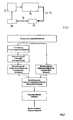
- Fig.1 schematically shows the structure of a control loop 10 for the control of the drive torque of a drive motor 12 of a commercial vehicle.
- the wheel speeds of the driven wheels present on a drive train 14 are measured via wheel speed sensors and corresponding signals are fed into a brake control unit 16 with integrated functional part for traction control ASR.
- This brake control unit 16 is, for example, via a CAN interface 18 to SAE J1939 with an engine control unit 20, which drives the drive motor 12. Via the interface 18, the brake control unit 16 can then deliver a desired value for the drive torque of the drive motor 12 to the engine control unit 20.
- Fig.2 shows the basic structure of the control structure of the engine torque control within the traction control system.
- a setpoint value for the wheel speed is calculated from the momentary wheel speed of a driven wheel, the instantaneous vehicle speed and a permissible drive slip. This setpoint is compared with the actual value of the current wheel speed and the speed control deviation determined.
- the brake control unit 16 calculates the setpoint value for the drive torque of the drive motor 12 with an electronic controller.
- the essential feature of this control therefore, is that the control variable calculated by the controller engages
- Target drive torque for the drive motor 12 is used as inputs but the wheel speeds of the driven wheels. Since further control loops are subordinate, which influence the drive torque of the drive motor 12, this setpoint specification in the engine control unit 20 is often not implemented identically.
- Purpose of in the WO 01/28802 described method is to avoid damage to differential gears or tires by excessive speed differences between the driven wheels of an axle.
- an essential difference is that with the known method the relative traction slip (wheel speed difference between the wheels of the front axle and the rear axle) between driven wheels of a vehicle is to be limited to a predetermined value while In traction control systems, however, the absolute drive slip of the driven wheels, ie the slip between the wheel and the road is adjusted to an optimum value in order to start or accelerate with the best adhesion between the wheel and the road.
- the present invention is therefore based on the object, such a method and an apparatus of the type mentioned in such a way that an engine speed control for traction control is easy to implement and works exactly.
- the invention uses an upper limit speed of the drive motor instead of the desired drive torque as an actuating variable.
- Upper limit speed means that the vehicle is operated up to this limit speed in the stable range of the traction slip curve or in the frictional maximum, while at above the upper limit speed beyond the unstable range of the power circuit slip curve is achieved.
- the upper limit speed represents a speed setpoint of the drive motor.
- the engine speed controller implemented in each engine control unit can adjust a speed specification much faster and more accurately than is possible by a drive torque specification.
- the invention thus avoids the detour via the control of the drive torque as a manipulated variable in the traction control system, whereby a controller and the necessary for this controller application costs for tuning the controller response to the vehicle or the drive motor deleted.
- a controller and the necessary for this controller application costs for tuning the controller response to the vehicle or the drive motor deleted.
- the speed controller which is already present in engine control units and tuned to the respective drive motor can be used. This results in a simpler structure and an improved control behavior.
- a mutual influence of different, on the drive torque as a control variable acting regulator avoided.
- the current gear ratio is calculated. Then, the upper limit value for the rotational speed of the drive motor can be calculated from the target wheel speed and the current transmission ratio.
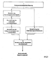
- FIG. 3 shows Figure 3 the basic structure of the control structure of an engine speed control within a traction control system according to a preferred embodiment of the invention.
- control circuit 10 for controlling the drive torque is in principle valid for a traction control ASR according to the invention by means of engine speed control, with the difference that according to the invention as a control variable of the control loop 10 not the drive torque of the drive motor 12, but a permissible upper limit speed of the drive motor 12 dependent is used by the present on the respective drive wheel or on a plurality of drive wheels slip.
- the traction control system is realized within an electronic brake system of a commercial vehicle and, in addition to the drive motor 12, also influences its brake system. Since the latter function is not essential to the invention, will not be discussed in the following.
- the drive motor 12 acts on the drive train 14, which consists for example of a transmission, a cardan shaft, a transfer case, the respective drive shafts and the driven wheels associated with a driven axle.
- the commercial vehicle can be driven on one as well as on two axles.
- the driven and non-driven wheels are associated with wheel speed sensors which control signals for the current wheel speed in the brake control unit 16, in which run, for example, routines for an additional existing ABS control and / or for an electronic stability program (ESP).
- ESP electronic stability program
- the brake control unit 16 is provided with an integrated functional part for traction control, which is connected, for example via a CAN interface 18 to SAE J1939 with the engine control unit 20.
- the latter in turn controls the power, torque and speed of the drive motor 12 and in particular includes an engine speed controller which is present anyway for other tasks.
- Figure 3 shows the basic structure of the control structure of the engine speed control, wherein the current wheel speed present at the respective drive wheel represents the input, which is detected according to function block 1 of the wheel speed sensors. Furthermore, the instantaneous engine speed is measured in a known manner.
- blocks 2 to 4 are already known from the prior art and relate to the calculation of the instantaneous vehicle speed in block 2, for example from the signals of the wheel speed sensors of non-driven axles. From this size and the wheel speeds of the driven wheels then the instantaneous slip of the drive wheels can be calculated during an acceleration process.
- the permissible or optimal drive slip is determined, for example, from stored traction slip characteristics, from which the desired wheel speeds of the driven wheels according to block 4 result.
- n_mot_max v_cmd * i_total
- n_mot_max consequently forms the speed setpoint for the engine speed controller integrated in the engine control unit 20 and is transmitted via the CAN interface 18.
- the control deviation between the upper limit n_mot_max and the actual engine speed is calculated by the speed controller 20.
- the speed setpoint value is then adjusted, for example, by a regulator acting on the throttle valve and in a self-igniting internal combustion engine by a controller acting on the diesel injection pump, with the respective actuator being controlled by the speed controller 20.
Landscapes
- Engineering & Computer Science (AREA)
- Chemical & Material Sciences (AREA)
- Combustion & Propulsion (AREA)
- Transportation (AREA)
- Mechanical Engineering (AREA)
- Control Of Vehicle Engines Or Engines For Specific Uses (AREA)
- Electric Propulsion And Braking For Vehicles (AREA)
- Regulating Braking Force (AREA)
- Control Of Driving Devices And Active Controlling Of Vehicle (AREA)
- Combined Controls Of Internal Combustion Engines (AREA)
Claims (6)
- Procédé à régler le patinage à l'accélération des roues motrices d'un véhicule entre les roues et la voie de circulation, dans lequel une grandeur de commande est calculée pour un moteur de commande (12) du véhicule sur la base d'une détection de la vitesse instantanée de roue et du calcul d'une vitesse théorique de roue, à ladite grandeur de commande étant formée par une valeur limite supérieure du nombre de tours dudit moteur de commande (12), caractérisé en ce que le rapport instantané des changements de vitesse et ladite valeur limite du nombre de tours dudit moteur de commande (12) sont calculés sur la base du nombre de tours instantané dudit moteur de commande (12) et de la vitesse de roue instantanée, par dérivation de la vitesse théorique de roue et du rapport instantané des changements de vitesse.
- Procédé selon la revendication 1, caractérisé en ce que la vitesse théorique de roue est calculée par dérivation de la vitesse instantanée du véhicule et d'une valeur admissible de patinage à l'accélération.
- Dispositif à régler le patinage à l'accélération des roues motrices d'un véhicule, à au moins un dispositif de manoeuvre (16), qui, à la base d'une détection de la vitesse instantanée de roue et du calcul d'une vitesse théorique de roue, calcule une grandeur de commande pour un moteur de commande (12) du véhicule, à ladite grandeur de commande étant formée par une valeur limite supérieure du nombre de tours dudit moteur de commande (12), caractérisé en ce que ledit au moins un dispositif de manoeuvre (16) est configuré d'une telle façon, qu'il calcule le rapport instantané des changements de vitesse et ladite valeur limite du nombre de tours dudit moteur de commande (12) sur la base du nombre de tours instantané dudit moteur de commande (12) et de la vitesse de roue instantanée, par dérivation de la vitesse théorique de roue et du rapport instantané des changements de vitesse.
- Dispositif selon la revendication 3, caractérisé en ce que ledit au moins un dispositif de manoeuvre (16) est un système de commande d'un système de freinage électronique (EBS) ou d'un système de freinage antiblocage (ABS).
- Dispositif selon la revendication 4, caractérisé en ce qu'un dispositif de commande du moteur (20) comprend un régulateur de vitesse qui règle ledit moteur de commande (12) à ladite valeur limite supérieure du nombre de tours.
- Dispositif selon les revendications 4 et 5, caractérisé en ce que ladite valeur limite supérieure du nombre de tours est réglée par ledit dispositif de manoeuvre (16) dans ledit dispositif de commande du moteur via une interface du type CAN.
Applications Claiming Priority (2)
| Application Number | Priority Date | Filing Date | Title |
|---|---|---|---|
| DE102006007740.7A DE102006007740B4 (de) | 2006-02-20 | 2006-02-20 | Verfahren und Vorrichtung zur Regelung des Antriebsschlupfes angetriebener Räder eines Fahrzeugs mit der Motordrehzahl als Stellgröße |
| PCT/EP2007/001403 WO2007096110A1 (fr) | 2006-02-20 | 2007-02-19 | Procédé et dispositif de régulation de l'antipatinage à l'accélération de roues entraînées d'un véhicule automobile, à l'aide de la vitesse de rotation du moteur en tant que grandeur de régulation |
Publications (2)
| Publication Number | Publication Date |
|---|---|
| EP1989087A1 EP1989087A1 (fr) | 2008-11-12 |
| EP1989087B1 true EP1989087B1 (fr) | 2009-08-12 |
Family
ID=38038605
Family Applications (1)
| Application Number | Title | Priority Date | Filing Date |
|---|---|---|---|
| EP07722843A Active EP1989087B1 (fr) | 2006-02-20 | 2007-02-19 | Procede et dispositif de regulation de l'antipatinage à l'acceleration de roues entraînees d'un vehicule automobile, à l'aide de la vitesse de rotation du moteur en tant que grandeur de regulation |
Country Status (6)
| Country | Link |
|---|---|
| US (1) | US9387843B2 (fr) |
| EP (1) | EP1989087B1 (fr) |
| JP (1) | JP2009527682A (fr) |
| AT (1) | ATE439283T1 (fr) |
| DE (2) | DE102006007740B4 (fr) |
| WO (1) | WO2007096110A1 (fr) |
Cited By (1)
| Publication number | Priority date | Publication date | Assignee | Title |
|---|---|---|---|---|
| DE102023113237A1 (de) | 2023-05-22 | 2024-11-28 | Dr. Ing. H.C. F. Porsche Aktiengesellschaft | Stabilisierungsverfahren und Fahrzeug |
Families Citing this family (8)
| Publication number | Priority date | Publication date | Assignee | Title |
|---|---|---|---|---|
| FR2885275A1 (fr) * | 2005-05-02 | 2006-11-03 | France Telecom | Procede d'ordonnancement de paquets appartenant a des flots et equipement associe |
| US8260509B2 (en) * | 2007-10-31 | 2012-09-04 | Caterpillar Inc. | Vehicle speed limiting via engine control commands issued by electronic transmission controller |
| DE102010029574B4 (de) | 2010-06-01 | 2024-03-28 | Robert Bosch Gmbh | Verfahren zur Einstellung eines Radmoments in einem Fahrzeug |
| DE102015222059A1 (de) * | 2015-11-10 | 2017-05-11 | Bayerische Motoren Werke Aktiengesellschaft | Fahrdynamikregelsystem in einem Kraftfahrzeug und elektronische Fahrdynamiksteuereinheit für ein Fahrdynamikregelsystem |
| DE102017124990B4 (de) | 2017-10-25 | 2021-11-04 | Dr. Ing. H.C. F. Porsche Aktiengesellschaft | Verfahren und System zum Betreiben eines Kraftfahrzeugs |
| DE102018207079A1 (de) * | 2018-05-07 | 2019-11-07 | Audi Ag | Verfahren zur Steuerung eines Antriebsmotors in einem Kraftfahrzeug |
| CN112455447B (zh) * | 2021-01-28 | 2021-05-14 | 天津所托瑞安汽车科技有限公司 | 车辆防滑控制方法、装置、电子设备及介质 |
| EP4108529B1 (fr) | 2021-06-24 | 2024-10-30 | Volvo Truck Corporation | Procédé permettant de commander la propulsion d'un véhicule utilitaire lourd |
Family Cites Families (6)
| Publication number | Priority date | Publication date | Assignee | Title |
|---|---|---|---|---|
| JPH0749786B2 (ja) * | 1987-12-25 | 1995-05-31 | 日産自動車株式会社 | 車両用駆動力制御装置 |
| DE19644231A1 (de) * | 1996-10-24 | 1998-04-30 | Teves Gmbh Alfred | Antriebsschlupfbegrenzereinrichtung |
| DE19837521B4 (de) | 1998-08-19 | 2013-05-23 | Robert Bosch Gmbh | Verfahren und Vorrichtung zur Antriebsschlupfregelung |
| DE19950035A1 (de) | 1999-10-16 | 2001-07-26 | Bosch Gmbh Robert | Verfahren und Vorrichtung zum Schutz von Differentialgetrieben eines Kraftfahrzeugs |
| JP3371889B2 (ja) * | 2000-04-17 | 2003-01-27 | トヨタ自動車株式会社 | 車両のスリップ制御 |
| JP2003327111A (ja) * | 2002-03-26 | 2003-11-19 | Robert Bosch Gmbh | 駆動滑り制御方法および装置 |
-
2006
- 2006-02-20 DE DE102006007740.7A patent/DE102006007740B4/de not_active Expired - Fee Related
-
2007
- 2007-02-19 AT AT07722843T patent/ATE439283T1/de active
- 2007-02-19 JP JP2008555679A patent/JP2009527682A/ja active Pending
- 2007-02-19 EP EP07722843A patent/EP1989087B1/fr active Active
- 2007-02-19 WO PCT/EP2007/001403 patent/WO2007096110A1/fr not_active Ceased
- 2007-02-19 US US12/224,060 patent/US9387843B2/en not_active Expired - Fee Related
- 2007-02-19 DE DE502007001297T patent/DE502007001297D1/de active Active
Cited By (1)
| Publication number | Priority date | Publication date | Assignee | Title |
|---|---|---|---|---|
| DE102023113237A1 (de) | 2023-05-22 | 2024-11-28 | Dr. Ing. H.C. F. Porsche Aktiengesellschaft | Stabilisierungsverfahren und Fahrzeug |
Also Published As
| Publication number | Publication date |
|---|---|
| WO2007096110A1 (fr) | 2007-08-30 |
| DE502007001297D1 (de) | 2009-09-24 |
| DE102006007740B4 (de) | 2014-01-02 |
| EP1989087A1 (fr) | 2008-11-12 |
| US9387843B2 (en) | 2016-07-12 |
| JP2009527682A (ja) | 2009-07-30 |
| DE102006007740A1 (de) | 2007-08-30 |
| US20100204895A1 (en) | 2010-08-12 |
| ATE439283T1 (de) | 2009-08-15 |
Similar Documents
| Publication | Publication Date | Title |
|---|---|---|
| EP1989087B1 (fr) | Procede et dispositif de regulation de l'antipatinage à l'acceleration de roues entraînees d'un vehicule automobile, à l'aide de la vitesse de rotation du moteur en tant que grandeur de regulation | |
| EP3116734B1 (fr) | Procédé de commande de moteurs électriques sur des véhicules hybrides à configuration en série ou des véhicules tout électriques équipés d'au moins deux essieux entraînés séparément | |
| EP3374224B1 (fr) | Système de régulation de la dynamique de conduite dans un véhicule automobile et unité de commande électronique de la dynamique de conduite pour un système de régulation de la dynamique de conduite | |
| EP2550171B1 (fr) | Véhicule doté d'au moins deux unités d'entraînement à roues individuelles | |
| DE102010015423A1 (de) | Antriebsvorrichtung für ein allradgetriebenes Fahrzeug | |
| DE102010047443A1 (de) | Kraftfahrzeug mit einem Allradantrieb | |
| EP3544849B1 (fr) | Système de transmission intégrale pour un véhicule automobile électrique et procédé permettant de faire fonctionner un système de transmission intégrale d'un tel véhicule | |
| WO2011131320A1 (fr) | Dispositif de fonctionnement pour une unité d'entraînement d'un véhicule à moteur | |
| DE102013219085A1 (de) | Verfahren und Steuervorrichtung zum Betrieb eines straßengekoppelten Hybridfahrzeuges | |
| DE102013113658B4 (de) | Verfahren zum Betreiben eines Triebstranges | |
| DE102010028486A1 (de) | Verfahren und Vorrichtung zum Betreiben eines Kraftfahrzeuges | |
| DE102019000846A1 (de) | Verfahren zur Überwachung einer Antriebsschlupfregelung eines Kraftfahrzeugs, entsprechendes Kraftfahrzeug sowie Regler | |
| DE102022204291A1 (de) | Verfahren zum Betreiben eines Steer-by-Wire-Lenksystems und Steer-by-Wire-Lenksystem | |
| DE19837521B4 (de) | Verfahren und Vorrichtung zur Antriebsschlupfregelung | |
| DE102010015424B4 (de) | Antriebsvorrichtung für ein allradgetriebenes Fahrzeug | |
| WO2018028854A1 (fr) | Procédé et dispositif pour faire fonctionner un véhicule à moteur et véhicule à moteur | |
| DE102021204464A1 (de) | Verfahren zur Ermittlung und Regelung kleinster Fahrdistanzen beim Einparken | |
| WO2000018623A1 (fr) | Dispositif et procede permettant d'influencer la propulsion d'un vehicule | |
| EP1670660A1 (fr) | Systeme de commande pour vehicules a motricite au moins temporairement integrale | |
| DE102004050994A1 (de) | Verfahren zum Steuern eines Antriebsystems in einem Kraftfahrzeug | |
| DE102006009064A1 (de) | Verfahren sowie Vorrichtung zur Regelung eines Antriebssystems | |
| DE102009026813A1 (de) | Verfahren zur Erzeugung eines auf die Fahrzeugräder eines Fahrzeugs wirkenden Differenzmoments | |
| DE102020202462A1 (de) | Verfahren zur Antriebsoptimierung in einem Kraftfahrzeug | |
| EP4638228A1 (fr) | Procédé de détermination d'un écart de performance entre une performance cible et une performance réelle d'un actionneur de véhicule | |
| DE19934376A1 (de) | Verfahren zur Antriebsschlupfregelung |
Legal Events
| Date | Code | Title | Description |
|---|---|---|---|
| PUAI | Public reference made under article 153(3) epc to a published international application that has entered the european phase |
Free format text: ORIGINAL CODE: 0009012 |
|
| 17P | Request for examination filed |
Effective date: 20080922 |
|
| AK | Designated contracting states |
Kind code of ref document: A1 Designated state(s): AT BE BG CH CY CZ DE DK EE ES FI FR GB GR HU IE IS IT LI LT LU LV MC NL PL PT RO SE SI SK TR |
|
| RIN1 | Information on inventor provided before grant (corrected) |
Inventor name: ZIEGLER, ANDREAS |
|
| GRAP | Despatch of communication of intention to grant a patent |
Free format text: ORIGINAL CODE: EPIDOSNIGR1 |
|
| DAX | Request for extension of the european patent (deleted) | ||
| GRAS | Grant fee paid |
Free format text: ORIGINAL CODE: EPIDOSNIGR3 |
|
| GRAA | (expected) grant |
Free format text: ORIGINAL CODE: 0009210 |
|
| AK | Designated contracting states |
Kind code of ref document: B1 Designated state(s): AT BE BG CH CY CZ DE DK EE ES FI FR GB GR HU IE IS IT LI LT LU LV MC NL PL PT RO SE SI SK TR |
|
| REG | Reference to a national code |
Ref country code: GB Ref legal event code: FG4D Free format text: NOT ENGLISH |
|
| REG | Reference to a national code |
Ref country code: CH Ref legal event code: EP |
|
| REG | Reference to a national code |
Ref country code: IE Ref legal event code: FG4D |
|
| REF | Corresponds to: |
Ref document number: 502007001297 Country of ref document: DE Date of ref document: 20090924 Kind code of ref document: P |
|
| LTIE | Lt: invalidation of european patent or patent extension |
Effective date: 20090812 |
|
| PG25 | Lapsed in a contracting state [announced via postgrant information from national office to epo] |
Ref country code: SE Free format text: LAPSE BECAUSE OF FAILURE TO SUBMIT A TRANSLATION OF THE DESCRIPTION OR TO PAY THE FEE WITHIN THE PRESCRIBED TIME-LIMIT Effective date: 20090812 Ref country code: ES Free format text: LAPSE BECAUSE OF FAILURE TO SUBMIT A TRANSLATION OF THE DESCRIPTION OR TO PAY THE FEE WITHIN THE PRESCRIBED TIME-LIMIT Effective date: 20091123 Ref country code: IS Free format text: LAPSE BECAUSE OF FAILURE TO SUBMIT A TRANSLATION OF THE DESCRIPTION OR TO PAY THE FEE WITHIN THE PRESCRIBED TIME-LIMIT Effective date: 20091212 Ref country code: FI Free format text: LAPSE BECAUSE OF FAILURE TO SUBMIT A TRANSLATION OF THE DESCRIPTION OR TO PAY THE FEE WITHIN THE PRESCRIBED TIME-LIMIT Effective date: 20090812 Ref country code: LT Free format text: LAPSE BECAUSE OF FAILURE TO SUBMIT A TRANSLATION OF THE DESCRIPTION OR TO PAY THE FEE WITHIN THE PRESCRIBED TIME-LIMIT Effective date: 20090812 |
|
| NLV1 | Nl: lapsed or annulled due to failure to fulfill the requirements of art. 29p and 29m of the patents act | ||
| PG25 | Lapsed in a contracting state [announced via postgrant information from national office to epo] |
Ref country code: LV Free format text: LAPSE BECAUSE OF FAILURE TO SUBMIT A TRANSLATION OF THE DESCRIPTION OR TO PAY THE FEE WITHIN THE PRESCRIBED TIME-LIMIT Effective date: 20090812 Ref country code: PL Free format text: LAPSE BECAUSE OF FAILURE TO SUBMIT A TRANSLATION OF THE DESCRIPTION OR TO PAY THE FEE WITHIN THE PRESCRIBED TIME-LIMIT Effective date: 20090812 Ref country code: NL Free format text: LAPSE BECAUSE OF FAILURE TO SUBMIT A TRANSLATION OF THE DESCRIPTION OR TO PAY THE FEE WITHIN THE PRESCRIBED TIME-LIMIT Effective date: 20090812 Ref country code: SI Free format text: LAPSE BECAUSE OF FAILURE TO SUBMIT A TRANSLATION OF THE DESCRIPTION OR TO PAY THE FEE WITHIN THE PRESCRIBED TIME-LIMIT Effective date: 20090812 |
|
| REG | Reference to a national code |
Ref country code: IE Ref legal event code: FD4D |
|
| PG25 | Lapsed in a contracting state [announced via postgrant information from national office to epo] |
Ref country code: PT Free format text: LAPSE BECAUSE OF FAILURE TO SUBMIT A TRANSLATION OF THE DESCRIPTION OR TO PAY THE FEE WITHIN THE PRESCRIBED TIME-LIMIT Effective date: 20091212 Ref country code: BG Free format text: LAPSE BECAUSE OF FAILURE TO SUBMIT A TRANSLATION OF THE DESCRIPTION OR TO PAY THE FEE WITHIN THE PRESCRIBED TIME-LIMIT Effective date: 20091112 |
|
| PG25 | Lapsed in a contracting state [announced via postgrant information from national office to epo] |
Ref country code: IE Free format text: LAPSE BECAUSE OF FAILURE TO SUBMIT A TRANSLATION OF THE DESCRIPTION OR TO PAY THE FEE WITHIN THE PRESCRIBED TIME-LIMIT Effective date: 20090812 Ref country code: DK Free format text: LAPSE BECAUSE OF FAILURE TO SUBMIT A TRANSLATION OF THE DESCRIPTION OR TO PAY THE FEE WITHIN THE PRESCRIBED TIME-LIMIT Effective date: 20090812 Ref country code: CZ Free format text: LAPSE BECAUSE OF FAILURE TO SUBMIT A TRANSLATION OF THE DESCRIPTION OR TO PAY THE FEE WITHIN THE PRESCRIBED TIME-LIMIT Effective date: 20090812 Ref country code: RO Free format text: LAPSE BECAUSE OF FAILURE TO SUBMIT A TRANSLATION OF THE DESCRIPTION OR TO PAY THE FEE WITHIN THE PRESCRIBED TIME-LIMIT Effective date: 20090812 Ref country code: EE Free format text: LAPSE BECAUSE OF FAILURE TO SUBMIT A TRANSLATION OF THE DESCRIPTION OR TO PAY THE FEE WITHIN THE PRESCRIBED TIME-LIMIT Effective date: 20090812 |
|
| PG25 | Lapsed in a contracting state [announced via postgrant information from national office to epo] |
Ref country code: SK Free format text: LAPSE BECAUSE OF FAILURE TO SUBMIT A TRANSLATION OF THE DESCRIPTION OR TO PAY THE FEE WITHIN THE PRESCRIBED TIME-LIMIT Effective date: 20090812 |
|
| PLBE | No opposition filed within time limit |
Free format text: ORIGINAL CODE: 0009261 |
|
| STAA | Information on the status of an ep patent application or granted ep patent |
Free format text: STATUS: NO OPPOSITION FILED WITHIN TIME LIMIT |
|
| 26N | No opposition filed |
Effective date: 20100517 |
|
| BERE | Be: lapsed |
Owner name: KNORR-BREMSE SYSTEME FUR NUTZFAHRZEUGE G.M.B.H. Effective date: 20100228 |
|
| PG25 | Lapsed in a contracting state [announced via postgrant information from national office to epo] |
Ref country code: GR Free format text: LAPSE BECAUSE OF FAILURE TO SUBMIT A TRANSLATION OF THE DESCRIPTION OR TO PAY THE FEE WITHIN THE PRESCRIBED TIME-LIMIT Effective date: 20091113 Ref country code: MC Free format text: LAPSE BECAUSE OF NON-PAYMENT OF DUE FEES Effective date: 20100301 |
|
| REG | Reference to a national code |
Ref country code: FR Ref legal event code: ST Effective date: 20101029 |
|
| PG25 | Lapsed in a contracting state [announced via postgrant information from national office to epo] |
Ref country code: FR Free format text: LAPSE BECAUSE OF NON-PAYMENT OF DUE FEES Effective date: 20100301 |
|
| PG25 | Lapsed in a contracting state [announced via postgrant information from national office to epo] |
Ref country code: BE Free format text: LAPSE BECAUSE OF NON-PAYMENT OF DUE FEES Effective date: 20100228 |
|
| PG25 | Lapsed in a contracting state [announced via postgrant information from national office to epo] |
Ref country code: IT Free format text: LAPSE BECAUSE OF FAILURE TO SUBMIT A TRANSLATION OF THE DESCRIPTION OR TO PAY THE FEE WITHIN THE PRESCRIBED TIME-LIMIT Effective date: 20090812 |
|
| REG | Reference to a national code |
Ref country code: CH Ref legal event code: PL |
|
| GBPC | Gb: european patent ceased through non-payment of renewal fee |
Effective date: 20110219 |
|
| PG25 | Lapsed in a contracting state [announced via postgrant information from national office to epo] |
Ref country code: LI Free format text: LAPSE BECAUSE OF NON-PAYMENT OF DUE FEES Effective date: 20110228 Ref country code: CH Free format text: LAPSE BECAUSE OF NON-PAYMENT OF DUE FEES Effective date: 20110228 |
|
| PG25 | Lapsed in a contracting state [announced via postgrant information from national office to epo] |
Ref country code: GB Free format text: LAPSE BECAUSE OF NON-PAYMENT OF DUE FEES Effective date: 20110219 |
|
| PG25 | Lapsed in a contracting state [announced via postgrant information from national office to epo] |
Ref country code: CY Free format text: LAPSE BECAUSE OF FAILURE TO SUBMIT A TRANSLATION OF THE DESCRIPTION OR TO PAY THE FEE WITHIN THE PRESCRIBED TIME-LIMIT Effective date: 20090812 |
|
| PG25 | Lapsed in a contracting state [announced via postgrant information from national office to epo] |
Ref country code: HU Free format text: LAPSE BECAUSE OF FAILURE TO SUBMIT A TRANSLATION OF THE DESCRIPTION OR TO PAY THE FEE WITHIN THE PRESCRIBED TIME-LIMIT Effective date: 20100213 Ref country code: LU Free format text: LAPSE BECAUSE OF NON-PAYMENT OF DUE FEES Effective date: 20100219 |
|
| PG25 | Lapsed in a contracting state [announced via postgrant information from national office to epo] |
Ref country code: TR Free format text: LAPSE BECAUSE OF FAILURE TO SUBMIT A TRANSLATION OF THE DESCRIPTION OR TO PAY THE FEE WITHIN THE PRESCRIBED TIME-LIMIT Effective date: 20090812 |
|
| REG | Reference to a national code |
Ref country code: AT Ref legal event code: MM01 Ref document number: 439283 Country of ref document: AT Kind code of ref document: T Effective date: 20120219 |
|
| PG25 | Lapsed in a contracting state [announced via postgrant information from national office to epo] |
Ref country code: AT Free format text: LAPSE BECAUSE OF NON-PAYMENT OF DUE FEES Effective date: 20120219 |
|
| P01 | Opt-out of the competence of the unified patent court (upc) registered |
Effective date: 20230528 |
|
| PGFP | Annual fee paid to national office [announced via postgrant information from national office to epo] |
Ref country code: DE Payment date: 20250226 Year of fee payment: 19 |