EP1989488B1 - Luftheiz- und -kühlvorrichtung - Google Patents
Luftheiz- und -kühlvorrichtung Download PDFInfo
- Publication number
- EP1989488B1 EP1989488B1 EP07705190A EP07705190A EP1989488B1 EP 1989488 B1 EP1989488 B1 EP 1989488B1 EP 07705190 A EP07705190 A EP 07705190A EP 07705190 A EP07705190 A EP 07705190A EP 1989488 B1 EP1989488 B1 EP 1989488B1
- Authority
- EP
- European Patent Office
- Prior art keywords
- air
- heat
- passage
- heating
- air passage
- Prior art date
- Legal status (The legal status is an assumption and is not a legal conclusion. Google has not performed a legal analysis and makes no representation as to the accuracy of the status listed.)
- Not-in-force
Links
Images








Classifications
-
- A—HUMAN NECESSITIES
- A47—FURNITURE; DOMESTIC ARTICLES OR APPLIANCES; COFFEE MILLS; SPICE MILLS; SUCTION CLEANERS IN GENERAL
- A47C—CHAIRS; SOFAS; BEDS
- A47C21/00—Attachments for beds, e.g. sheet holders or bed-cover holders; Ventilating, cooling or heating means in connection with bedsteads or mattresses
- A47C21/04—Devices for ventilating, cooling or heating
-
- A—HUMAN NECESSITIES
- A47—FURNITURE; DOMESTIC ARTICLES OR APPLIANCES; COFFEE MILLS; SPICE MILLS; SUCTION CLEANERS IN GENERAL
- A47C—CHAIRS; SOFAS; BEDS
- A47C21/00—Attachments for beds, e.g. sheet holders or bed-cover holders; Ventilating, cooling or heating means in connection with bedsteads or mattresses
- A47C21/04—Devices for ventilating, cooling or heating
- A47C21/042—Devices for ventilating, cooling or heating for ventilating or cooling
- A47C21/044—Devices for ventilating, cooling or heating for ventilating or cooling with active means, e.g. by using air blowers or liquid pumps
-
- A—HUMAN NECESSITIES
- A47—FURNITURE; DOMESTIC ARTICLES OR APPLIANCES; COFFEE MILLS; SPICE MILLS; SUCTION CLEANERS IN GENERAL
- A47C—CHAIRS; SOFAS; BEDS
- A47C21/00—Attachments for beds, e.g. sheet holders or bed-cover holders; Ventilating, cooling or heating means in connection with bedsteads or mattresses
- A47C21/04—Devices for ventilating, cooling or heating
- A47C21/048—Devices for ventilating, cooling or heating for heating
-
- F—MECHANICAL ENGINEERING; LIGHTING; HEATING; WEAPONS; BLASTING
- F24—HEATING; RANGES; VENTILATING
- F24F—AIR-CONDITIONING; AIR-HUMIDIFICATION; VENTILATION; USE OF AIR CURRENTS FOR SCREENING
- F24F3/00—Air-conditioning systems in which conditioned primary air is supplied from one or more central stations to distributing units in the rooms or spaces where it may receive secondary treatment; Apparatus specially designed for such systems
- F24F3/001—Air-conditioning systems in which conditioned primary air is supplied from one or more central stations to distributing units in the rooms or spaces where it may receive secondary treatment; Apparatus specially designed for such systems in which the air treatment in the central station takes place by means of a heat-pump or by means of a reversible cycle
-
- F—MECHANICAL ENGINEERING; LIGHTING; HEATING; WEAPONS; BLASTING
- F24—HEATING; RANGES; VENTILATING
- F24F—AIR-CONDITIONING; AIR-HUMIDIFICATION; VENTILATION; USE OF AIR CURRENTS FOR SCREENING
- F24F5/00—Air-conditioning systems or apparatus not covered by F24F1/00 or F24F3/00, e.g. using solar heat or combined with household units such as an oven or water heater
- F24F5/0042—Air-conditioning systems or apparatus not covered by F24F1/00 or F24F3/00, e.g. using solar heat or combined with household units such as an oven or water heater characterised by the application of thermo-electric units or the Peltier effect
-
- F—MECHANICAL ENGINEERING; LIGHTING; HEATING; WEAPONS; BLASTING
- F24—HEATING; RANGES; VENTILATING
- F24F—AIR-CONDITIONING; AIR-HUMIDIFICATION; VENTILATION; USE OF AIR CURRENTS FOR SCREENING
- F24F5/00—Air-conditioning systems or apparatus not covered by F24F1/00 or F24F3/00, e.g. using solar heat or combined with household units such as an oven or water heater
- F24F5/0096—Air-conditioning systems or apparatus not covered by F24F1/00 or F24F3/00, e.g. using solar heat or combined with household units such as an oven or water heater combined with domestic apparatus
-
- F—MECHANICAL ENGINEERING; LIGHTING; HEATING; WEAPONS; BLASTING
- F24—HEATING; RANGES; VENTILATING
- F24H—FLUID HEATERS, e.g. WATER OR AIR HEATERS, HAVING HEAT-GENERATING MEANS, e.g. HEAT PUMPS, IN GENERAL
- F24H3/00—Air heaters
- F24H3/02—Air heaters with forced circulation
- F24H3/04—Air heaters with forced circulation the air being in direct contact with the heating medium, e.g. electric heating element
- F24H3/0405—Air heaters with forced circulation the air being in direct contact with the heating medium, e.g. electric heating element using electric energy supply, e.g. the heating medium being a resistive element; Heating by direct contact, i.e. with resistive elements, electrodes and fins being bonded together without additional element in-between
- F24H3/0411—Air heaters with forced circulation the air being in direct contact with the heating medium, e.g. electric heating element using electric energy supply, e.g. the heating medium being a resistive element; Heating by direct contact, i.e. with resistive elements, electrodes and fins being bonded together without additional element in-between for domestic or space-heating systems
- F24H3/0417—Air heaters with forced circulation the air being in direct contact with the heating medium, e.g. electric heating element using electric energy supply, e.g. the heating medium being a resistive element; Heating by direct contact, i.e. with resistive elements, electrodes and fins being bonded together without additional element in-between for domestic or space-heating systems portable or mobile
-
- F—MECHANICAL ENGINEERING; LIGHTING; HEATING; WEAPONS; BLASTING
- F24—HEATING; RANGES; VENTILATING
- F24H—FLUID HEATERS, e.g. WATER OR AIR HEATERS, HAVING HEAT-GENERATING MEANS, e.g. HEAT PUMPS, IN GENERAL
- F24H3/00—Air heaters
- F24H3/12—Air heaters with additional heating arrangements
-
- F—MECHANICAL ENGINEERING; LIGHTING; HEATING; WEAPONS; BLASTING
- F25—REFRIGERATION OR COOLING; COMBINED HEATING AND REFRIGERATION SYSTEMS; HEAT PUMP SYSTEMS; MANUFACTURE OR STORAGE OF ICE; LIQUEFACTION SOLIDIFICATION OF GASES
- F25B—REFRIGERATION MACHINES, PLANTS OR SYSTEMS; COMBINED HEATING AND REFRIGERATION SYSTEMS; HEAT PUMP SYSTEMS
- F25B21/00—Machines, plants or systems, using electric or magnetic effects
- F25B21/02—Machines, plants or systems, using electric or magnetic effects using Peltier effect; using Nernst-Ettinghausen effect
- F25B21/04—Machines, plants or systems, using electric or magnetic effects using Peltier effect; using Nernst-Ettinghausen effect reversible
Definitions
- the present invention relates to an air heating and cooling device for supplying temperature conditioned air flow, particularly although not exclusively, to an air mattress device.
- such temperature controllable materials may be formed from a thermo setting plastics material, having a plurality of relatively thicker fibers arranged in a first direction, crossed by a plurality of laterally undulating thinner fibers in a second direction both above and below the thicker fibres.
- Parallel to the thicker fibers in the first direction may be provided a plurality of thermo setting fibers, such that when the thicker fibers in the first direction are bonded to the thinner fibers in a second direction and heat is applied, the thermo setting thinner fibers in the first direction contract, thereby pulling the thicker fibers into a series of vertical undulations, and forming a plurality of air channel between a sandwich of upper and lower relatively thinner fibers.
- This hollow material can be covered with upper and lower layers of fabric to produce a hollow resilient pad which is comfortable to sit or lay on, and through which air can be passed. By temperature controlling the air, the pad can be heated up or cooled down.
- a known heating device for an air temperature controlled mattress has dimensions of the order 40 cm width, 80 cm length, and 50 cm height, which is an inconveniently sized air supply unit for a domestic use.
- DE 203 13 149U1 discloses a compact air conditioning unit of a type which is intended to be used for air blankets, air mattresses or like devices.
- the technical problem addressed by that device is noise reduction, since temperature conditioners for use in bedrooms need to be silent or quiet to avoid disturbing a person sleeping, and the technical solution is to provide silencers on the fans for the exhaust channel and temperature conditioned air channel.
- the air inlets and outlets are at the ends of the device, which limits the surface area of the air inlets and outlets, and limits the quantity and volume of air flow which can be heated/ cooled for a particular size of device, as well as limiting the orientations in which the device can be placed. Acceptability of the device for consumer use is limited due to bulk and weight of device for a given cooling or heating performance, and the limitations of where the device can be placed in a room.
- a device (200) for temperature conditioning an air supply for an air conditioned appliance said device characterised by comprising;
- the device may further comprise a stand alone separate power supply for converting mains voltage electricity to a lower voltage electricity below mains voltage.
- said casing comprises an elongate tube like structure, having a plurality of air inlets and outlets on a first side, and having a second side which is continuous and devoid of any air inlet/outlet grills, upon which the device may be stood on a floor. This may enable the device to be placed in a plurality of orientations and allow flexibility in positioning the device adjacent a bed.
- said substantially tubular casing is substantially rectangular in cross section.
- said elongate tubular casing is divided into a plurality of air passages, by a plurality of bulk heads which extend across a width of said tubular casing.
- the device may further comprise a flexible and extendible hose through which air can be pumped, a said air outlet and allowing said device to be placed underneath said mattress in use on a bed.
- Said flexible air hose comprises an extension which enables the heating and cooling device to be moved between a first orientation in which a face of said device containing a plurality of air inlets and outlets is positioned facing upwardly, and a second orientation in which said face is positioned facing substantially horizontally.
- FIG. 1 there is illustrated schematically a mattress cover 100 for fitting onto a bed, the mattress cover formed from a hollow resilient material having a plurality of air channels passing there through; and an air heating and cooling device 101 for supplying heated or cooled air to the mattress cover 100, such that when heated air is supplied by the heating and cooling device, the mattress cover becomes warm relative to an ambient air temperature, and when cooled air is supplied by the cooling device 101, the mattress cover 100 becomes cooled relative to the ambient air temperature.
- the heating and cooling device 101 supplies air to the mattress cover 100 via a supply tube 102.
- Air flow through the heating and cooling device and mattress cover is in a single direction. External ambient air enters the heating and cooling device 101, is either heated or cooled, and is pumped through the delivery tube 102 to the mattress cover 100. Alternatively, heating or cooling may not be applied, and the air may be kept at the same ambient temperature and pumped through the supply tube 102 into the mattress cover 100.
- the heating and cooling device comprises an outer casing 200, which can be a variety of different shapes but in a best mode is in a rectangular "brick" shape, the outer casing having an air inlet 201 for drawing air in from the atmosphere, and an air outlet 202 for expelling atmospheric air; an outlet pipe 203, through which air is pumped, the air having been temperature conditioned by the heating and cooling device either by heating the air, maintaining the air at its ambient temperature, or cooling the air; and a power supply cable 204.
- an outer casing 200 which can be a variety of different shapes but in a best mode is in a rectangular "brick" shape, the outer casing having an air inlet 201 for drawing air in from the atmosphere, and an air outlet 202 for expelling atmospheric air; an outlet pipe 203, through which air is pumped, the air having been temperature conditioned by the heating and cooling device either by heating the air, maintaining the air at its ambient temperature, or cooling the air; and a power supply cable 204.
- air inlet 201 and air outlet 202 are on a same face of the casing. This enables the heating and cooling device to be placed in a maximum number of orientations on a floor surface, up or against a wall or other item of furniture.
- there are two surfaces on which the heating and cooling device cannot be rested this being an upper surface 205 on which the air inlet and air outlet are present, and an end surface 206 out of which the supply tube 203 and electrical connector cable 204 are positioned on.
- the heating and cooling device can be placed to rest on any of the remaining force on obstructed surfaces. Further, the heating and cooling device can be placed on its base surface, and a first or second side surface or a second end surface 207 may abut an adjoining wall or item of furniture.
- FIG 3 there is illustrated schematically in plan view from above, components of the heating and cooling device.
- the heating device comprises a base plate 300 onto which other components are mounted; an inlet fan 301 for drawing atmospheric air into the device; a plurality of air channels 302 for passage of air through the device; an array of Peltier heating and cooling devices 303 arranged in series and parallel; a plurality of heat sinks 304, 305 situated in the air passages, and arranged such that air flows through the heat sinks, the heat sinks arranged for sinking heating to and from the Peltier heating devices; an outlet extractor fan 306 for drawing waste air out of the device; a power supply unit 307 for powering the Peltier devices, inlet and outlet fans, and a control circuit; and a control circuit 308 for controlling the heating and cooling device; and an outlet 309 for passage of conditioned air from the heating and cooling device.
- FIG 4 there is illustrated schematically in view from an opposite side, the heating and cooling device of figure 3 showing passage of air through the device.
- the heating and cooling device comprises an upper air channel 400 and a lower air channel 401.
- the upper and lower air channels being separated from each other by the array of Peltier effect devices 303. Arrows indicate the direction of air flow in each of the upper and lower air channels.
- each heat sink comprises a metal body formed into a shape of fins in order to maximise heat exchange between the heat sink and the air passing through the heat sink, whilst providing minimised disruption to the air flow through the lower heating/cooling passage.
- the air passes through the ceramic heater device 310, and through to the outlet pipe 309.
- the upper air channel 400 has a plurality of inlet apertures 404, 405 oppositely facing each other, from which air may be drawn in from inside the casing, the air having entered the casing via inlet apertures 201 in the casing.
- Air entering via rear aperture 404 passes through a first upper heat sink 304 and is drawn out of the upper air channel by extractor fan 306 and out of the casing via outlet apertures 202 as herein before described.
- air entering from the casing into the front inlet 405 of the upper air channel passes through second heat sink 305, drawn through the heat sink by the electric extractor fan 306 and out of the casing via outlet apertures 202.
- the heating and cooling device is capable of three modes of operation being heating the ambient air, cooling the ambient air, or maintaining the air at its existing ambient temperature.
- Peltier devices 303 are positioned between the first set of heat sinks in the heating/cooling channel 401, and the second set of heat sinks 304, 305 in the exhaust air channel 400.
- operation of the heating and cooling device is as follows.
- the plurality of Peltier devices 303 are controlled so as to pump heat from the exhaust heat sinks 304, 305 to the heating/cooling channel heat sinks 402, 403 so that the heat sinks in the lower heating/cooling air channel become relatively warmer compared to the heat sinks in the exhaust air channel, and the heat sinks in the air heating/cooling channel become hot enough to heat the air passing through the channel.
- Air is drawn into the heating/cooling channel via the inlet fan 301, passes through the first and second heat sinks of the air heating/cooling channel and then through the ceramic heater 310 in order to obtain an extra boost of heating, before being expelled through the air outlet 309.
- the exhaust air channel 400 draws in air through its first and second inlets 404, 405 respectively, and over the first and second exhaust heat sinks 304, 305.
- the air flow over the exhaust heat sinks prevents the Peltier devices over heating, and enables a temperature differential between the exhaust air, and the air supply to the mattress.
- Heat is extracted from the exhaust air passing through the exhaust channel and transferred to the air supply outlet 309, the heat being pumped between the two air flows by the array of Peltier heat pump devices 303.
- operation of the device is as follows.
- air is drawn in through the inlet fan 301 and passes through the first and second heat sink 402, 403 respectively in the air conditioning channel, and then through the ceramic heater 310 and out through the air supply outlet 309.
- the ceramic heater 310 is turned off so as not to heat the air-
- the Peltier devices operate to cool the first and second lower heat sinks in the air conditioning channel, relative to ambient atmospheric air temperature so that air passing through the air conditioning channel experiences a reduction in temperature-
- the Peltier devices 303 pump heat from the heat sinks in the air conditioning channel to the heat sink 304, 305 in the exhaust channel.
- outlet fan 306 draws air through the first and second inlets 404, 405 respectively of the exhaust channel and through the exhaust heat sinks 305, 306. Since the exhaust heat sinks 304, 305 are at a relatively higher temperature than the air conditioning heat sinks 402, 403 heat is transferred to the exhaust air flow and is expelled through the exhaust outlet apertures 202 of the device.
- the Peltier devices are turned off and the ceramic heater is also turned off so that no active heating or cooling of the air in the air conditioning channel occurs.
- Air is drawn into the inlet of the air conditioning channel by the inlet fan 306, is forced through the air conditioning channel heat sinks and through the ceramic heater, each of which are in an "off" condition supplying no heat and extracting no heat, and out of the outlet 309.
- the exhaust channel 400 may be inactive, with the exhaust fan 306 being turned off in order to save power.
- the lay out, design of the air channels and component selection needs to be optimised in order to achieve a practically workable heating and cooling device which is of an acceptable size and weight for domestic use.
- FIG. 5 there is illustrated schematically a first prototype heating and cooling device according to a second specific embodiment, showing a practical air passageway, shape and layout and positioning of components within a casing.
- a second embodiment heating and cooling device comprises a base plate 500 onto which is mounted a tubular structure 501 forming an air conditioning air channel, and an upper tubular structure 502 forming an exhaust channel.
- the air conditioning channel 501 comprises a substantially rectangular cross sectional tubular passage having at an inlet end a tapered inlet 503 and an outlet end, a tapered outlet portion 504.
- Within the air conditioning channel are positioned one or a plurality of cast aluminum heat sink devices 504, 505, through which the air is forced by inlet fan 506.
- Inlet fan 506 is placed with its main axis of rotation substantially perpendicular to a main plane of the base plate 500, so as to draw air in from a direction transverse to the main plane of the base plate.
- Air therefore passes through 90 degrees through the fan to be expelled in a transverse direction along a main length of the air conditioning passageway 501.
- the ceramic heating device 506 is positioned in the air conditioning channel in the air flow, after the heat sinks and Peltier heat pump devices, and before the outlet 507.
- the exhaust air channel 508 comprises a substantially tubular structure, substantially rectangular in cross section, having first and second apertures at opposite ends of the tubular structure, the tubular structure having a central aperture over which an exhaust fan 511 is fitted such that the exhaust fan draws air through the outlet aperture in the upper face of the exhaust passage, whilst the air is drawn in through the first and second opposite air inlets. Air is drawn from the inlets, over a plurality of heat sink devices and out of the outlet of the exhaust passage, under the force of the electric extractor fan 511.
- the Peltier devices are positioned between the exhaust heat sinks and the air conditioning heat sinks to pump heat between the exhaust heat sinks and the air conditioning heat sinks. Depending upon how the Peltier devices are driven, the flow of heat between the exhaust heat sinks and the air conditioning heat sinks can be reversed, and increased or decreased as desired.
- the overall dimensions of the heating and cooling device are in the range width 15 to 36 cm; height 7 to 15 cm, and length 20 to 40 cm.
- the exhaust air passage may have an internal cross sectional area through which air flows, of dimensions in the range 30 cm 2 to 108 cm 2 .
- the air conditioning air channel may have an internal cross sectional area in a direction perpendicular to a main airflow direction in the range 30 cm 2 to 120 cm 2 .
- each Peltier effect device may have dimensions in the range 40 mm x 40 mm, and an array of Peltier effect devices may comprise eight individual devices arranged in two sets of four devices, the two sets being positioned serially within the device.
- FIG 6 there is illustrated schematically the second embodiment heating and cooling device of fig 5 shown in disassembled end view.
- the mouldings surrounding the exhaust air channel and the air conditioning air channel are formed of transparent plastics material, so that the internal heat sink components and ceramic heater components are visible.
- the forward heat sink of the exhaust channel which is formed as an aluminum casting, having a plurality of parallel extending fins which are positioned in a direction along the exhaust air channel, so that air flows between the fins.
- the air passing through the exhaust channel is exposed to a maximum fin area, over a maximum distance between the inlet and outlet of the exhaust channel, whilst at the same time impeding to a minimum extent, the passage of air.
- Figure 7 illustrates schematically a probe layout on top of an air mattress, of the type having a plurality of air channels within the mattress;
- 15 probes are arranged in an array of five rows and three columns, spaced approximately equidistantly from each other and covering the whole of an area of an air mattress suitable for covering a double divan sized bed.
- Figure 8 illustrates schematically a plot of temperature against time for temperature probes placed at a plurality of positions on the air mattress of fig 7 , when supplied with temperature conditioned air by a heating and cooling device according to a specific embodiment herein;
- an upper surface of the air mattress was tested to rise within 6 minutes, to a temperature of between one and fourteen degrees above ambient temperature at the start of the test, and after twelve minutes, tended towards a range of between four and fourteen degrees above initial ambient temperature.
- Figure 9 illustrates schematically a plot of temperature against time for an air mattress supplied with cooled air from a heating and cooling device according to a specific embodiment herein.
- the heating and cooling device was tested as being capable of driving a double divan sized air mattress in steady state operation, with a temperature variation of around 1.5 °C across the mattress surface, with the overall temperature being in the range of between 2 and 3.2 °C below ambient temperature.
- Figure 10 illustrates schematically a plot of temperature against time measured by a series of probes placed on an air mattress supplied with temperature controlled air from a heating and cooling device as described herein wherein a 10 tog quilt covers the air mattress, with the quilt facing down.
- the heating and cooling device was tested as being capable of producing an increase of temperature of up to 11°C within 2 minutes of commencing the heating mode, and maintaining a surface temperature of the air mattress in the range up to 17 °C above ambient temperature as measured at the beginning of the test.
- Figure 11 illustrates an equivalent plot to figure 10 , with a 10 tog quilt covering an air mattress, but with the quilt facing the other way up.
- the heating and cooling device was shown to be capable of driving the air mattress so as to produce a surface temperature on the air mattress surface of between 3 and 14 °C above ambient temperature at the start of the test, within a 6 minute period from the start of the heating mode, and of achieving a temperature in the range 6 to 15 °C above ambient temperature at the start of the test within a period of 12 minutes from the start of the test.
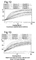
- Figure 12 illustrates schematically a plot of temperature against time for an air mattress supplied with temperature conditioned air by a heating and cooling device according to an embodiment described herein, where an impervious material is placed underneath the air mattress.
- the heating and cooling device was capable of driving the air mattress to give temperatures in the range 5 to 17°C above ambient temperature at the start of the test, within 6 minutes of commencement of the heating mode test.
- Figure 13 illustrates schematically a plot of temperature against time for a plurality of positions on an air mattress supplied with temperature conditioned air wherein an impervious material is placed underneath the air mattress, and a % portion of the air mattress is covered by a blanket.
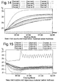
- Figure 14 illustrates schematically a plot of temperature against time for an air mattress supplied with temperature conditioned air by a specific embodiment heating and cooling device herein, wherein an impervious material is placed underneath the air mattress and the air mattress has a different inlet nozzle, where the heating and cooling device is operated in a heating mode.
- the heating and cooling device was capable of driving the air mattress to achieve a mattress surface temperature in the range 6 to 19°C above ambient temperature at the start of the test, after a one hour period.
- Figure 15 illustrates schematically an equivalent plot to figure 14 , but with the heating and cooling device driven in a cooling mode.
- the device With the heating and cooling device in a cooling mode, the device was capable of driving an air mattress having an impervious material below the mattress to a temperature in the range 2 to 4°C below ambient temperature after a one hour period, and to maintain that temperature range indefinitely thereafter.
- Figure 16 illustrates schematically a plot of temperature against time for the air mattress driven as in figure 14 , but with a 400 mm length of the upper surface of the air mattress covered by an impervious material.
- the heating and cooling device In a heating mode, with impervious material placed below an air mattress and a lower 400 mm of the mattress upper surface covered by a blanket, after 2 hours from start of the test, the heating and cooling device was found capable of driving the surface temperature of the air mattress to a temperature of between 10 and 17 °C above ambient, and of maintaining that temperature range indefinitely thereafter.
- Figure 17 illustrates schematically a plot equivalent to that of figure 16 , but wherein the heating and cooling device has been left on for a long period, for example all night.
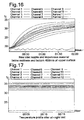
- Figure 18 illustrates schematically a plot of temperature against time for an air mattress driven by a heating and cooling device as described herein in a cooling mode, with a replacement inlet nozzle and an impervious material below the mattress and covering a 400 mm length of upper surface of the air mattress.
- the heating and cooling device was tested to be capable of driving an air mattress having an impervious material below the mattress and a bottom 400 mm of the surface covered by a blanket, to a cooled temperature, in the range 1.5 to 6 °C below the corresponding ambient temperature at the start of the test, after a period of one hour from test commencement.
- Figure 19 illustrates schematically a plot equivalent to that of figure 19 , but wherein the air mattress has been left for an extended period, for example overnight and has reached a steady state temperature condition.
- the heating and cooling device in a cooling mode was tested as driving a mattress at a temperature range of between 2 and 4 °C below ambient external atmospheric temperature.
- Figure 20 illustrates schematically a third air heating and cooling device according to a third specific embodiment, in cut away side view.
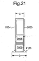
- Figure 21 illustrates schematically the third air heating and cooling device in end view.
- the main difference compared to the first and second devices are the overall proportions of the device and the amended layout which allows use of the device in a more restricted space.
- the third heating and cooling device may be stood end on, in the form of a floor standing "tower” device, or can be laid flat underneath a bed.
- the device has an outer casing in the form of a substantially flat rectangular "brick" shape.
- the device has first and second sides 2000, 2001, first and second ends 2002, 2003, a top panel 2004 and a bottom panel 2005.
- the device may be rotated through 90 degrees and stood on its side, so the top and the bottom panels become the sides in that orientation. In the orientation shown on figure 20 , the device is viewed from above.
- the device may have dimensions of length (A) in the range 500 to 560 mm, and preferably around 540mm; width (B) in the range 200 to 300 mm ; and height (C) in the range 50 to 70 mm.
- the proportions of the device allow its use in a restricted space, for example underneath a bed.
- the device can be laid flat under a bed, with an air intake on the top 2004 of the device, and air outlets at one end 2002 of the device.
- the device comprises the following internal components:
- a first air channel, for heating and cooling air comprises a first chamber 2016, open to the air at one side, where the apertures are, the first chamber containing the air filter 2012 and first fan 2007, and an air passage through the first heat sink 2008 of the heat exchanger, terminating in an outlet 2017, which connects to an air supply tube to an air mattress device.
- a second air channel, for waste air comprises a second chamber 2018 which is open to the air via a plurality of inlet apertures, and containing the second fan 2013, the second fan channeling air through a passage 2019 which leads to a second heat sink 2010 of the heat exchanger, and through an exhaust vent 2020.
- the air filter 2012 may be accessible by a removable cover on the top panel 2004, or by a removable cover elsewhere on the device.
- the air filter may be shaped so as to fit around the inlet fan.
- the air filter may be disposable, and replaceable when contaminated.
- the purpose of the air filter is to remove airborne contaminates such as solid particles, dust, pollen, mould, and bacteria from the air.
- a range of filter materials may be used including paper, foam, synthetic plastics or natural fibers such as cotton.
- Cotton air filters may be used because of their durability and good air flow properties. Examples of synthetic materials which may be used for replaceable air filters include polyester fiber. Alternatively, spun fiber filters may be used.
- an allergy resistant filter such as a micro-fiber filter may be used to remove common allergens such as dust, pollen, bacteria or other air born particles.
- the filter may be provided as a filter cartridge, which can be slotted into a front end of the first air channel, at a position either before or after the inlet fan in the first air flow.
- the first and second air channels are separated from each other by a dividing wall 2021, and by the Peltier devices 2011 and the bases of the first and second heat sink devices. Heat is transferred between the first and second air channels by the heat exchanger 2008 - 2011 by operation of the Peltier devices under control of the electronic control unit 2015 as herein before described.
- An additional benefit of the third air heating and cooling device is that the fan for waste heat is more efficient, and is able to bring the cooled air down to between 6 and 8 °C below ambient air temperature.
- the external dimensions of the first heat exchanger give a volume occupied of the order of 0.4 m 3 .
- the waste channel heat exchanger has similar external dimensions.
- the first air fan 2007 intakes air through the filter unit 2012, and passes the air through the first heat exchanger 2008, which is heated by the Peltier devices 2011.
- the waste heat fan 2013 is on a low rate of air throughput.
- the power point of the waste heat fan is increased to increase the air flow through the waste heat channel.
- the waste heat fan may be capable of reducing the input air to 6 to 8 °C below ambient, providing a cooled air stream through the waste heat exchanger.
- the Peltier effect devices pumping heat from the first heat exchanger 2008 to the second heat exchanger 2010, this enables cooling of the inlet air in the air conditioning channel relative to ambient.
- an optional detachable base portion 2100 may be fitted on one side of the heating and cooling device, so that the device can be stood on end, taking up minimal floor space.
- the base may have a footprint area in the range length 500 - 560 mm, and width 80 - 120 mm, and preferably of the order of 100 mm.
- air is inlet through the top (now a side) and is outlet at the first end. Only two faces of the case are used for air inlet and outlet, optimizing the air flow and possible orientations in which the device may be placed.
- FIG 22 there is illustrated schematically a fourth air heating and cooling device according to a fourth specific embodiment.
- the device is shown with its front cover removed.
- the fourth air heating and cooling device comprises a double unit, capable of providing conditioned air to two air mattresses via two heat conditioning modules in a single device.
- the device effectively two single air heating and cooling devices placed side by side in a single casing 2200.
- the front of the casing is removed to show internal components.
- the fourth embodiment heating and cooling device relies on an external power supply, in a separate casing, which may be connected to the fourth heating and cooling device via an electrical cable 2201 which enters the rear of the casing, at a position approximately mid way along the length of the casing.
- Each individual air heating and cooling device within the casing comprises a primary heat exchanger axial fan for drawing air through a heat sink device 2203 in an air conditioned air channel; a heat exchanger device comprising a first heat sink 2203 and a second heat sink, the first and second heat sinks being separated by a plurality of heat pump devices, for example Peltier effected devices; an air filter unit 2204 for filtering incoming air to an air temperature conditioning channel within the device; a waste heat fan 2202 for forcing air through a waste heat channel and an electronic control circuit 2205 for controlling the main fan and waste heat fan.
- a primary heat exchanger axial fan for drawing air through a heat sink device 2203 in an air conditioned air channel
- a heat exchanger device comprising a first heat sink 2203 and a second heat sink, the first and second heat sinks being separated by a plurality of heat pump devices, for example Peltier effected devices
- an air filter unit 2204 for filtering incoming air to an air temperature conditioning channel within the device
- the filter 2204 is contained within a filter cartridge, which slides into a slot in the casing and is removable without the need to remove the front of the casing.
- the cartridge By pushing an outer face of the filter cartridge, the cartridge, which is resiliently biased and attached to the casing by a catch mechanism, ejects from the cartridge slot, enough to allow a user to grip the end of the cartridge using their fingers and slide the cartridge out of the slot.
- the first and second heating and cooling modules are separated within the overall casing by a plurality of bulkheads 2205, 2206 positioned substantially mid way along the length of the device. Airflow paths within the first heating device are fully isolated and separate from the airflow paths within the second device, within the same outer casing.
- the unit can be placed face up on the floor, with the air inlets and outlets facing upwards, thereby enabling the device to occupy a low profile, and possibly to be stored underneath a bed.
- the device can be placed as shown in figure 22 , in an upright position, in which the fans draw and expel air in a substantially horizontal direction relative to a floor on which the casing stands.
- FIG 23 there is illustrated schematically the fourth air heating and cooling device of figure 22 in view from the front, with the front of the casing in place, showing the inlet and outlet air vents. Waste air is drawn in through a first set of grills 2300, 2301 through a waste heat sink by a first waste air axial fan 2302 and out of a second grill 2303.
- Conditioned air is drawn in through a third grill 2304 by a conditioned air channel centrifugal fan 2305 and passes behind the waste fan and waste eat sink, in separate channel at the rear of the device, passing through a second heat sink and out of a conditioned air outlet 2306. Bulkheads in the casing separate the incoming and outgoing waste air.
- FIG 24 there is illustrated schematically the fourth air heating and cooling device in view from the rear, showing a smooth rear surface suitable for resting the device on a carpet floor or other surface.
- FIG 25 there is shown in disassembled view the fourth heating and cooling device with the filters removed and showing the air flow paths of the waste / exhaust air cannel and the heated/ cooled air supply to the outlet which connect to the mattress.
- the incoming exhaust air channel is contained between first and second dividing bulkheads 2500, 2501 either side of the main exhaust fan and passes into the vanes of one of the outer heat sink of the heat exchanger and out through the main exhaust fan.
- the air passes along the vanes of the heat exchanger in both directions towards the fan and underneath the bulkheads 2500, 2501 from the adjacent side chambers 2504, 2505 either side of the fan which are open to the outside via grill in the front of the casing.
- an incoming flow of air 2503 is drawn in to the side chambers, and is then urged in a lateral direction perpendicular to its original direction as it encounters the heat sink of the heat exchanger.
- the air is then drawn out via the main exhaust fan, out of the second grill area immediately in front of the exhaust fan.
- the chambers either side of the fan are each defined between a respective pair of bulkheads which extend across the casing, either side of a grill on the front of the casing.
- the air then exhausts via the second grill openings in the front of the casing. Cool air comes in at the sides of the exhaust fan and warmed air is forced out by the fan.
- the air flow in the exhaust air channel is similar, or the fan can be turned off or on low speed.
- the air flow in the heated or cooled air supply to the mattress is as follows, looking at one heating/ cooling unit only.
- Ambient air is drawn in via an inlet chamber 2508 through an inlet grill in the front of the casing and through a filter (not shown in figure 25 ) into an inlet fan 2509.
- the inlet fan is enclosed, having an annular inlet in its enclosure for the inlet of air, and channels the air into a passage adjacent the rear casing, which takes the air through the vanes of the other heat sink of the heat exchanger.
- the air flow passes along the full length of the vanes of the second heat sink so it enters on side of the heat sink and passes the whole way along the heat exchanger until it exits at the other side.
- the air is either heated in which case heat is taken fro the ambient air drawn in the exhaust cannel and transferred to the conditioned air channel, via the Peltier heat pumps transferring heat form the exhaust heat sink to the main heating / cooling heat sink, or if the device is in cooling mode, the Peltier devices transfer heat from the conditioned air to the exhaust air, in which case the exhaust air leaves the device at a higher temperature than it enters, since it carries waste heat.
- the chamber at the other side of the heat sink is connected to the conditioned air outlet of the device for supply to the mattress via a supply tube.
- Each of the separate modules in the double module device of figures 22 to 25 can be independently controlled so that one module can be operated in heating mode which the other module is operated in a cooling mode, or vice versa, or both modules can be operated in the same mode, e.g. both cooling or both heating. Since each module is independently controllable, the extent of heating or cooling in each module is independent from the other.
- the power supply comprises an interference suppressed transformer which converts mains voltage power to a lower voltage, e.g. 48 volts, which is safer for use in the heating and cooling device.
- the power supply is of dimensions in the range: Width: 110mm to 130mm, and preferably 120mm Height: 150mm to 170 mm, and preferably 160mm Length: 810mm to 840 mm and preferably 830mm.
- the power supply is intended to be positioned away from the heating and cooling device and at a safe position away from any potentially combustible material such as bedding or blankets.
- the filter device comprises a filter cartridge body 2700 which contains a removable filter 2701.
- the cartridge slides into and out of a corresponding receiving channel in the casing and locates there by a set of grooves 2702 on the sides of the cartridge.
- a spring mechanism 2703, 2704 in the form of a pair of resilient fingers, which in use urge against the casing so the when the cartridge is pushed on its outer face 2705, it locks in to the casing and when pushed again it springs out of the casing, urged by the resilient biasing means 2703, 2704.
- a catch positioned on the casing at the receiving slot for the filter allows the cartridge to engage and lock into the slot or spring out of the slot.
- the filter is removable and replaceable by detaching the cartridge from the device.
- a range of allergenic or non allergenic filters may be substituted in the filter cartridge.
- the fifth heating/ cooling device comprises an outer casing 2800 of a substantially tubular rectangular cross section having rounded edges, with a front side 2801, a rear side, an upper side 2801 and a lower side, and first and second ends 2802, 2803.
- An air outlet 2804 is provided approximately mid way along a length of the device for supplying air to a mattress as described herein before.
- the fifth device comprises all of the components described with respect to the fourth embodiment herein, except that only components for one air outlet are present.
- a primary heat exchanger fan for pushing air through a heat sink device in an air conditioning channel; a heat exchanger device comprising a first heat sink and a second heat sink, the first and second heat sinks being separated by a plurality of heat pump devices, for example Peltier effected devices; an air filter unit for filtering incoming air to an air temperature conditioning channel within the device; a waste heat fan for forcing air through a waste heat channel; and an electronic control circuit for controlling the main fan and a waste heat fan.
- a heat exchanger device comprising a first heat sink and a second heat sink, the first and second heat sinks being separated by a plurality of heat pump devices, for example Peltier effected devices
- an air filter unit for filtering incoming air to an air temperature conditioning channel within the device
- a waste heat fan for forcing air through a waste heat channel
- an electronic control circuit for controlling the main fan and a waste heat fan.
- a filter is contained within a spring loaded removable filter cartridge 2805, which slides into a slot in the casing and is removable without the need to remove the front or rear of the casing.
- the cartridge By pushing an outer face of the filter cartridge, the cartridge, which is resiliently biased and attached to the casing by a catch mechanism, ejects from the cartridge slot, enough to allow a user to grip the end of the cartridge using their fingers and slide the cartridge out of the slot.
- the filter cartridge may be removed when the device is positioned upright as shown or when the device is laid on its rear side. In either case the cartridge is positioned in the casing such that it is freely accessible buy a user without he need to lift the device.
- Dimensions of the casing, in the best mode may be in the following ranges: Width: 110mm to 130mm, and preferably 120mm Height: 150mm to 170 mm, and preferably 160mm Length: 120mm to 160 mm.
- the device is powered by a separate power supply unit, which can be placed away from the heating and cooling device so that the device can be made more compact and lightweight.
- the device may be positioned in use, as shown in figure 28 , standing on its lower side, so that the air inlets for the main fan are positioned on the front side of the device, drawing air in horizontally, or alternatively the device may be laid on its rear side so that air intakes for the main fan are facing upwardly.
- FIG 29 there is illustrated the fifth heating and cooling device in view from the front.
- a primary heat exchanger fan 3000 is seen visible through an inlet/outlet grill 2901 comprising the front of the casing.
- FIG 30 there is illustrated schematically the rear of the fifth heating and cooling device shown in figures 28 and 29 .
- On the rear face there are no air inlets or outlets.
- a power supply lead 3003 enters the casing at a mid position of the casing.
- the air outlet to a mattress device is positioned between the rear face and the upper face, at a position that the air outlet does not protrude above the main plane of the rear face. This enables the air outlet to lie flat when the device is rested on its rear side.
- the remote control device comprises a power on control 3101 for powering up or powering down the device to turn it on or off, a temperature increase control 3102 for increasing the temperature of air output by the heating/ cooling device, and a temperature down device for decreasing the temperature of air output by the heating I cooling device.
- the remote device can select either one of the two modules to control this independently in the case of a double unit as shown in figs 22 to 25 .
- the cooling device may be provided with one or more flexible and extendible hoses to connect the temperature conditioned air outlets with the air mattress air inlets, so that the device can be placed adjacent a bed, or underneath the bed.
- the hose may have and extension portion to enable the casing of the heating and cooling device to be placed lying down with the ambient air inlets and outlets face up, or alternatively facing horizontally, with the temperature conditioned air outlets to the mattress being on an opposite face of the casing substantially perpendicular, or at least transverse, to the face having the plurality of air inlets and outlets for ambient and exhaust air.
Landscapes
- Engineering & Computer Science (AREA)
- Mechanical Engineering (AREA)
- General Engineering & Computer Science (AREA)
- Chemical & Material Sciences (AREA)
- Combustion & Propulsion (AREA)
- Life Sciences & Earth Sciences (AREA)
- Sustainable Development (AREA)
- Thermal Sciences (AREA)
- Physics & Mathematics (AREA)
- Mattresses And Other Support Structures For Chairs And Beds (AREA)
- Devices For Blowing Cold Air, Devices For Blowing Warm Air, And Means For Preventing Water Condensation In Air Conditioning Units (AREA)
- Heating, Cooling, Or Curing Plastics Or The Like In General (AREA)
- Compressor (AREA)
- Air Filters, Heat-Exchange Apparatuses, And Housings Of Air-Conditioning Units (AREA)
Claims (17)
- Vorrichtung (200) für die Temperierung einer Luftzufuhr für ein klimatisiertes Gerät, wobei die genannte Vorrichtung dadurch gekennzeichnet ist, dass sie Folgendes umfasst:ein äußeres Gehäuse;einen ersten Luftdurchgang zum Leiten eines ersten Luftstroms;einen zweiten Luftdurchgang zum Leiten eines zweiten Luftstroms;ein einziges Einlassgebläse (301, 506) zum Saugen von Luft in den genannten ersten Luftdurchgang;ein Abluftgebläse (306, 511) zum Saugen von Luft durch den genannten zweiten Luftdurchgang; undeinen oder mehrere Wärmetauscher (303 - 305) zum Austauschen von Wärme zwischen Luft in dem genannten ersten Luftdurchgang und Luft in dem genannten zweiten Abluftdurchgang;wobei der genannte erste Luftdurchgang einen röhrenförmigen Kanal mit einem Einlass (201) an einem ersten Ende und einem Auslass (203, 309) umfasst, wobei sich der genannte Auslass an einem zweiten Ende des genannten ersten Luftdurchgangs befindet, und das genannte Einlassgebläse (301, 506) an dem genannten Einlass positioniert ist, so dass der genannte erste Luftstrom durch das genannte Einlassgebläuse, entlang dem gesamten genannten ersten Luftdurchgang, so dass er auf alle des genannten einen bzw. der genannten mehreren Wärmetauscher (303 - 305) trifft, und aus dem genannten Auslass heraus geleitet wird;wobei der genannte zweite Luftdurchgang eine röhrenförmige Wand mit einem Einlass und einem in der genannten röhrenförmigen Wand positionierten Auslass (202) umfasst;wobei der genannte eine oder mehrere Wärmetauscher in der genannten röhrenförmigen Wand positioniert sind, so dass der genannte zweite Luftstrom über den genannten einen bzw. die genannten mehreren Wärmetauscher strömt; undwobei das genannte Abluftgebläse (306, 511) an dem genannten Auslass (202) des genannten zweiten Luftdurchgangs positioniert ist, um Luft durch den genannten Einlass des genannten zweiten Luftdurchgangs, über den genannten einen bzw. die genannten mehreren Wärmetauscher und aus dem genannten Auslass (309) des genannten zweiten Luftdurchgangs heraus zu saugen;wobei sich der Einlass (201) des ersten Luftdurchgangs und der Auslass (202) des zweiten Luftdurchgang an einer selben Oberfläche des äußeren Gehäuses der Vorrichtung befinden.
- Vorrichtung nach Anspruch 1, wobei sich der Einlass des zweiten Luftdurchgangs an der selben Oberfläche des äußeren Gehäuses der Vorrichtung befindet wie der genannte Einlass des genannten ersten Luftdurchgangs und der genannte Auslass des genannten zweiten Luftdurchgangs.
- Vorrichtung nach einem der vorangehenden Ansprüche, umfassend einen ausbaubaren und austauschbaren Einlassluftfilter zum Filtern von Luft, die in den genannten ersten Luftdurchgang eintritt.
- Vorrichtung nach Anspruch 2, wobei der genannte austauschbare Filter ein Filtermaterial umfasst, das dazu geeignet ist, Allergene aus dem genannten ersten Luftstrom zu entfernen.
- Vorrichtung nach einem der vorangehenden Ansprüche, wobei das genannte Abluftgebläse (306, 511) an einem Auslass des genannten zweiten Durchgangs positioniert ist, um Luft durch einen oder mehrere Einlässe (404, 405) des genannten zweiten Durchgangs und durch den genannten Auslass des genannten zweiten Durchgangs zu saugen.
- Vorrichtung nach Anspruch 1, wobei ein genannter Wärmetauscher Folgendes umfasst:eine erste Wärmesenke (402, 403), die sich in den genannten ersten Luftdurchgang erstreckt, so dass durch den genannten ersten Luftdurchgang strömende Luft Wärme mit der genannten ersten Wärmesenke austauscht;eine zweite Wärmesenke (304, 305), die sich in den genannten zweiten Luftdurchgang erstreckt, so dass in dem genannten zweiten Luftdurchgang strömende Luft Wärme mit der genannten zweiten Wärmesenke austauscht; undeine oder mehrere elektrisch angetriebene Peltiereffekt-Wärmepumpenvorrichtungen, die zwischen der genannten ersten und der genannte zweiten Wärmesenke positioniert sind, wobei die genannten Peltiervorrichtungen fähig sind, in einem Kühlmodus Wärme in einer ersten Richtung von der genannten ersten Wärmesenke zu der genannten zweiten Wärmesenke zu pumpen, um Luft in dem genannten ersten Durchgang zu kühlen und fähig sind, in einem Heizmodus Wärme von der genannten zweiten Wärmesenke zu der genannten ersten Wärmesenke zu pumpen, um Luft in dem genannten ersten Durchgang zu erwärmen,
- Vorrichtung nach einem der vorangehenden Ansprüchen, wobei die genannte Wärmetauschervorrichtung Folgendes umfasst:einen ersten Satz von Wärmesenkenvorrichtungen 402, 403, die in dem genannten ersten Luftdurchgang positioniert sind;einen zweiten Satz von Wärmesenkenvorrichtungen (304, 305), die in dem genannten zweiten Luftdurchgang positioniert sind; undeine oder mehrere elektrische Wärmepumpenvorrichtungen (303), die zwischen dem genannten ersten und dem genannten zweiten Satz von Wärmesenken positioniert sind, um Wärme zwischen dem genannten ersten und dem genannten zweiten Satz von Warmesenken zu übertragen,
- Vorrichtung nach Anspruch 7, wobei eine genannte Wärmepumpenvorrichtung eine oder mehrere Peltiereffektvorrichtungen (303) umfasst.
- Vorrichtung nach einem der vorangehenden Ansprüche zum Zuführen temperierter Luft an eine Luftmatratze (100) mit mehreren Luftdurchgängen, die für den Strom von Luft dadurch hindurch ausgelegt sind.
- Vorrichtung nach einem der vorangehenden Ansprüche, die fähig ist, temperierte Luft an eine Luftmatratze in Doppeldiwangröße zuzuführen, so dass beim Auslösen eines Heizmodus eine Temperatur an einer Oberfläche der genannten Luftmatratze über einen Zeitraum von 12 Minuten über einen Bereich von fünf bis fünfzehn Grad Celsius zunimmt.
- Vorrichtung nach einem der vorangehenden Ansprüche, die fähig ist, temperierte Luft an eine Luftmatratze in Doppeldiwangröße zuzuführen, so dass in einem Kühlmodus eine Oberflächentemperatur der genannten Luftmatratze eine Temperatur von zwischen zwei und vier Grad unter der Temperatur der Umgebungsaußenluft erreicht.
- Vorrichtung nach einem der vorangehenden Ansprüche, die fähig ist, temperierte Luft an eine Luftmatratze in Doppeldiwangröße zuzuführen, so dass in einem Kühlmodus nach einem fünfstündigen Zeitraum vom Auslösen des genannten Kühlmodus eine Lufttemperatur der genannten Luftmatratze im Bereich von zwischen zwei und drei Grad unter der Temperatur der Umgebungsaußenluft liegt.
- Vorrichtung nach einem der vorangehenden Ansprüche mit Gesamtaußenabmessungen in folgenden Bereichen:Breite: 15 cm bis 36 cmHöhe: 7 cm bis 15 cmLänge: 20 cm bis 40 cm
- Vorrichtung nach einem der vorangehenden Ansprüche, wobei der genannte erste Luftdurchgang eine innere Querschnittsfläche in einer Richtung senkrecht zu einer Hauptrichtung des Luftstroms im Bereich von 30 cm2 bis 120 cm2 aufweist.
- Vorrichtung nach einem der vorangehenden Ansprüche, wobei der genannte zweite Luftdurchgang (400) eine innere Querschnitksfläche in einer Richtung senkrecht zu einer Hauptrichtung des Luftstroms im Bereich von 30 cm2 bis 108 cm2 aufweist.
- Vorrichtung nach einem der vorangehenden Ansprüche, wobei ein genannter Wärmetauscher Folgendes umfasst:eine obere Wärmesenke, umfassend mehrere Rippen, die sich parallel zu einer Hauptrichtung des Luftstroms in dem genannten ersten Durchgang erstrecken; undeine zweite Wärmesenke, umfassend mehrere langgestreckte Rippen, die sich parallel zu einer Hauptrichtung des Luftstroms in dem genannten zweiten Luftdurchgang erstrecken;vier Peltiereffekt-Wärmepumpenvorrichtungen mit jeweils einer aktiven oberen Oberfläche im Bereich von 625 mm2 bis 2025 mm2 und mit einer zweiten aktiven Fläche mit Abmessungen im Bereich von 625 mm2 bis 1600 mm2.
- Vorrichtung nach einem der vorangehenden Ansprüche, in Kombination mit einer Luftmatratze (100), wobei die genannte Luftmatratze mehrere Fasern umfasst, die mehrere allgemein parallele Röhren bilden, die nebeneinander angeordnet sind, wobei die genannten mehreren Fasern Luftspalte dazwischen aufweisen, um das Austreten von durch die genannten mehreren Röhren strömender Luft zuzulassen, so dass die genannte Luft über im Wesentlichen eine gesamte obere Oberfläche der genannten Luftmatratze freigesetzt wird.
Applications Claiming Priority (2)
| Application Number | Priority Date | Filing Date | Title |
|---|---|---|---|
| GB0603292A GB2435320B (en) | 2006-02-17 | 2006-02-17 | A device for temperature conditioning an air supply |
| PCT/GB2007/000502 WO2007093783A2 (en) | 2006-02-17 | 2007-02-15 | Air heating and cooling device |
Publications (2)
| Publication Number | Publication Date |
|---|---|
| EP1989488A2 EP1989488A2 (de) | 2008-11-12 |
| EP1989488B1 true EP1989488B1 (de) | 2012-01-25 |
Family
ID=36142082
Family Applications (1)
| Application Number | Title | Priority Date | Filing Date |
|---|---|---|---|
| EP07705190A Not-in-force EP1989488B1 (de) | 2006-02-17 | 2007-02-15 | Luftheiz- und -kühlvorrichtung |
Country Status (10)
| Country | Link |
|---|---|
| US (1) | US7908687B2 (de) |
| EP (1) | EP1989488B1 (de) |
| JP (1) | JP2009528502A (de) |
| CN (1) | CN101400949A (de) |
| AT (1) | ATE543052T1 (de) |
| AU (1) | AU2007216366A1 (de) |
| CA (1) | CA2642428A1 (de) |
| GB (1) | GB2435320B (de) |
| WO (1) | WO2007093783A2 (de) |
| ZA (1) | ZA200807089B (de) |
Cited By (1)
| Publication number | Priority date | Publication date | Assignee | Title |
|---|---|---|---|---|
| TWI714307B (zh) * | 2019-10-14 | 2020-12-21 | 致茂電子股份有限公司 | 電源供應器 |
Families Citing this family (54)
| Publication number | Priority date | Publication date | Assignee | Title |
|---|---|---|---|---|
| EP2606771B1 (de) | 2006-10-13 | 2015-01-07 | Gentherm Incorporated | Klimatisiertes Bett |
| GB2446572B (en) * | 2007-02-15 | 2011-09-07 | Richards Morphy N I Ltd | Temperature controlled mattress pad |
| WO2009036077A1 (en) | 2007-09-10 | 2009-03-19 | Amerigon, Inc. | Operational control schemes for ventilated seat or bed assemblies |
| US9125497B2 (en) * | 2007-10-15 | 2015-09-08 | Gentherm Incorporated | Climate controlled bed assembly with intermediate layer |
| US8281609B1 (en) * | 2008-03-14 | 2012-10-09 | Rothschild Jesse B | Man portable micro-climate |
| KR100994143B1 (ko) * | 2008-06-23 | 2010-11-12 | 이동철 | 히터 |
| AU2009270757B2 (en) | 2008-07-18 | 2016-05-12 | Gentherm Incorporated | Climate controlled bed assembly |
| US8893329B2 (en) * | 2009-05-06 | 2014-11-25 | Gentherm Incorporated | Control schemes and features for climate-controlled beds |
| US8332975B2 (en) | 2009-08-31 | 2012-12-18 | Gentherm Incorporated | Climate-controlled topper member for medical beds |
| DE202010001244U1 (de) | 2010-01-21 | 2011-05-26 | Stiebel Eltron GmbH & Co. KG, 37603 | Luft/Wasser-Wärmepumpe für eine Außenaufstellung |
| CH702645A1 (de) * | 2010-02-05 | 2011-08-15 | Mentus Holding Ag | Thermisch aktiver Isolator. |
| KR101002676B1 (ko) * | 2010-02-18 | 2010-12-21 | 윤장호 | 온열기능을 갖는 스프링 타입 매트리스 |
| US20110247134A1 (en) * | 2010-04-09 | 2011-10-13 | Howell Charles A | Siderail accessory module |
| EP2912974A3 (de) * | 2010-05-28 | 2015-12-09 | Marlow Industries, Inc. | System für ein entsprechend persönlichem komfort gesteuertes thermoelektrisches Bett |
| US8353069B1 (en) * | 2010-09-07 | 2013-01-15 | Miller Anthony W | Device for heating, cooling and emitting fragrance into bedding on a bed |
| EP2838745A1 (de) | 2012-04-17 | 2015-02-25 | Climazleeper Holding ApS | Transportmittel mit batteriebetriebener kühlung eines schlafenden fahrers |
| WO2014022419A1 (en) | 2012-07-30 | 2014-02-06 | Marlow Industries, Inc. | Thermoelectric personal comfort controlled bedding |
| CA2885466C (en) | 2012-10-18 | 2018-05-22 | Tempur-Pedic Management, Llc | Support cushions and methods for controlling surface temperature of same |
| US10247452B2 (en) * | 2012-12-17 | 2019-04-02 | Yi-Ming Tseng | Device and method for supporting a person |
| US9131781B2 (en) | 2012-12-27 | 2015-09-15 | Select Comfort Corporation | Distribution pad for a temperature control system |
| US11812859B2 (en) | 2013-03-15 | 2023-11-14 | Sleepme Inc. | System for enhancing sleep recovery and promoting weight loss |
| US12576237B2 (en) | 2013-03-15 | 2026-03-17 | Sleep Solutions Inc. | Smart platform for stress reduction and sleep promotion |
| US11883606B2 (en) | 2013-03-15 | 2024-01-30 | Sleep Solutions Inc. | Stress reduction and sleep promotion system |
| US11633053B2 (en) | 2013-03-15 | 2023-04-25 | Sleepme Inc. | Weighted blanket with thermally regulated fluid |
| US11813076B2 (en) | 2013-03-15 | 2023-11-14 | Sleepme Inc. | Stress reduction and sleep promotion system |
| US11896774B2 (en) | 2013-03-15 | 2024-02-13 | Sleep Solutions Inc. | System for enhancing sleep recovery and promoting weight loss |
| US12208216B2 (en) | 2015-09-15 | 2025-01-28 | Sleep Solutions Inc. | System for enhancing sleep recovery and promoting weight loss |
| US11602611B2 (en) | 2013-03-15 | 2023-03-14 | Sleepme Inc. | System for enhancing sleep recovery and promoting weight loss |
| US10986933B2 (en) | 2013-03-15 | 2021-04-27 | Kryo, Inc. | Article comprising a temperature-conditioned surface, thermoelectric control unit, and method for temperature-conditioning the surface of an article |
| CN103266645B (zh) * | 2013-05-03 | 2014-06-11 | 浙江大学 | 仿生便携式雾气集水器 |
| CN103466092A (zh) * | 2013-10-11 | 2013-12-25 | 中国商用飞机有限责任公司 | 用于机门区域的加热系统及方法 |
| US9907407B2 (en) * | 2014-05-13 | 2018-03-06 | Mark Darius Aramli | Blanket apparatus for distributing conditioned air into zones of a bed |
| CA2936688C (en) | 2014-01-13 | 2021-11-30 | Bedgear, Llc | Ambient bed having a heat reclaim system |
| CN103844705A (zh) * | 2014-03-21 | 2014-06-11 | 南京航空航天大学 | 一种可调控温床及其工作方法 |
| US20150282631A1 (en) * | 2014-04-08 | 2015-10-08 | Jim Creamer | Temperature Control Pad |
| WO2015157523A1 (en) * | 2014-04-10 | 2015-10-15 | Advanced Thermal Solutions, Inc. | Multiple flow entrance heat sink |
| US9888785B2 (en) | 2014-04-21 | 2018-02-13 | Casper Sleep Inc. | Mattress |
| US10499755B2 (en) * | 2014-05-13 | 2019-12-10 | Bedjet Llc | Bed covering apparatus equipped with an air inlet that has a fastener for selectively opening and closing the air inlet |
| US10342358B1 (en) | 2014-10-16 | 2019-07-09 | Sleep Number Corporation | Bed with integrated components and features |
| AU2015392446A1 (en) * | 2015-04-23 | 2017-11-09 | Tempur-Pedic Management, Llc | Support cushions and methods for active ventilation of same |
| US10827845B2 (en) | 2017-02-24 | 2020-11-10 | Sealy Technology, Llc | Support cushions including a support insert with a bag for directing air flow, and methods for controlling surface temperature of same |
| WO2019036393A1 (en) | 2017-08-14 | 2019-02-21 | Casper Sleep Inc. | MATTRESSES CONTAINING ERGONOMIC ENDOSQUELET AND CLOSURE REGULATION |
| US10772438B2 (en) | 2017-08-23 | 2020-09-15 | Sleep Number Corporation | Air system for a bed |
| KR101951569B1 (ko) * | 2017-11-02 | 2019-05-20 | 김상동 | 무덕트형 공기청정 환기장치 |
| US11241100B2 (en) | 2018-04-23 | 2022-02-08 | Casper Sleep Inc. | Temperature-regulating mattress |
| US11160386B2 (en) | 2018-06-29 | 2021-11-02 | Tempur World, Llc | Body support cushion with ventilation system |
| US20220357076A1 (en) * | 2019-07-03 | 2022-11-10 | Magic Carpet Ltd | Portable space heater and surface heating system |
| USD908398S1 (en) | 2019-08-27 | 2021-01-26 | Casper Sleep Inc. | Mattress |
| USD927889S1 (en) | 2019-10-16 | 2021-08-17 | Casper Sleep Inc. | Mattress layer |
| USD1064213S1 (en) | 2020-06-16 | 2025-02-25 | Rheem Manufacturing Company | Heat pump water heater |
| US11506420B2 (en) * | 2020-06-16 | 2022-11-22 | Rheem Manufacturing Company | Retrofit heat pump water heating systems |
| CN112493750A (zh) * | 2020-11-26 | 2021-03-16 | 杭州浩然公寓有限公司 | 舒适性好带调温结构的沙发 |
| WO2022124603A1 (ko) * | 2020-12-09 | 2022-06-16 | 코웨이 주식회사 | 송풍 매트리스 및 송풍 매트리스를 포함하는 침대 |
| WO2022173547A1 (en) * | 2021-01-26 | 2022-08-18 | Ergomotion, Inc. | Under base integral climate control for an articulating bed |
Family Cites Families (13)
| Publication number | Priority date | Publication date | Assignee | Title |
|---|---|---|---|---|
| US4777802A (en) * | 1987-04-23 | 1988-10-18 | Steve Feher | Blanket assembly and selectively adjustable apparatus for providing heated or cooled air thereto |
| BR8805330A (pt) * | 1988-10-14 | 1990-05-29 | Feher Steve | Cobertor para conexao a um fornecimento de ar pressurizado modificado pela temperatura e aparelho |
| US5555579A (en) * | 1994-03-03 | 1996-09-17 | Wu; Wen-Pin | Mattress assembly with semiconductor thermo-control |
| US5448788A (en) * | 1994-03-08 | 1995-09-12 | Wu; Shuenn-Jenq | Thermoelectric cooling-heating mattress |
| AU2522597A (en) | 1996-04-18 | 1997-11-07 | Ace Bed Co., Ltd. | Temperature controller for bedding |
| JPH10132435A (ja) * | 1996-10-31 | 1998-05-22 | Aisin Seiki Co Ltd | 冷却装置 |
| US6119463A (en) | 1998-05-12 | 2000-09-19 | Amerigon | Thermoelectric heat exchanger |
| WO2002058165A1 (en) * | 2000-12-26 | 2002-07-25 | Cheolhyeon Choi | Coolness and warmth bed for using peltier's effect |
| FI112537B (fi) | 2001-05-23 | 2003-12-15 | Vallox Oy | Lämmön talteenottokennon tiivistysjärjestely |
| US6935122B2 (en) * | 2003-03-18 | 2005-08-30 | Chiu Kuang Hsing Co., Ltd. | Air feeding apparatus |
| US6826792B2 (en) * | 2003-03-29 | 2004-12-07 | Jeng Ming Lin | Air mattress having temperature regulator |
| DE20313149U1 (de) | 2003-08-26 | 2004-03-18 | Schröter, Ingo | Kompakt transportable Klimaanlage |
| US8151391B2 (en) * | 2008-09-23 | 2012-04-10 | Jacobo Frias | Inflatable temperature control system |
-
2006
- 2006-02-17 GB GB0603292A patent/GB2435320B/en not_active Expired - Fee Related
-
2007
- 2007-02-15 EP EP07705190A patent/EP1989488B1/de not_active Not-in-force
- 2007-02-15 AU AU2007216366A patent/AU2007216366A1/en not_active Abandoned
- 2007-02-15 US US12/224,081 patent/US7908687B2/en not_active Expired - Fee Related
- 2007-02-15 AT AT07705190T patent/ATE543052T1/de active
- 2007-02-15 CA CA002642428A patent/CA2642428A1/en not_active Abandoned
- 2007-02-15 WO PCT/GB2007/000502 patent/WO2007093783A2/en not_active Ceased
- 2007-02-15 CN CNA2007800087677A patent/CN101400949A/zh active Pending
- 2007-02-15 JP JP2008554838A patent/JP2009528502A/ja active Pending
-
2008
- 2008-08-18 ZA ZA200807089A patent/ZA200807089B/xx unknown
Cited By (1)
| Publication number | Priority date | Publication date | Assignee | Title |
|---|---|---|---|---|
| TWI714307B (zh) * | 2019-10-14 | 2020-12-21 | 致茂電子股份有限公司 | 電源供應器 |
Also Published As
| Publication number | Publication date |
|---|---|
| CA2642428A1 (en) | 2007-08-23 |
| ATE543052T1 (de) | 2012-02-15 |
| US20100235991A1 (en) | 2010-09-23 |
| GB2435320A (en) | 2007-08-22 |
| US7908687B2 (en) | 2011-03-22 |
| ZA200807089B (en) | 2009-07-29 |
| AU2007216366A1 (en) | 2007-08-23 |
| GB0603292D0 (en) | 2006-03-29 |
| JP2009528502A (ja) | 2009-08-06 |
| WO2007093783A2 (en) | 2007-08-23 |
| EP1989488A2 (de) | 2008-11-12 |
| CN101400949A (zh) | 2009-04-01 |
| GB2435320B (en) | 2008-10-08 |
| WO2007093783A3 (en) | 2007-12-06 |
Similar Documents
| Publication | Publication Date | Title |
|---|---|---|
| US7908687B2 (en) | Device for temperature conditioning an air supply | |
| US8490412B2 (en) | Thermoelectric personal environment appliance | |
| US10045630B2 (en) | System and method for thermoelectric personal comfort controlled bedding | |
| CN100419347C (zh) | 热电个人环境装置 | |
| US20140137569A1 (en) | System and method for thermoelectric personal comfort controlled bedding | |
| US20150282631A1 (en) | Temperature Control Pad | |
| EP0575433A1 (de) | Personliches luftklimatisierungssystem | |
| US6963488B1 (en) | Device to convey the cool air from an air-conditioner into a computer | |
| CN209219648U (zh) | 一种分区调温床垫 | |
| CN111770700B (zh) | 冷却系统 | |
| CN217057764U (zh) | 集水装置和空调器 | |
| WO2016030774A1 (en) | Device for a climate controlled ambience and method thereof | |
| EP1369655A1 (de) | Wärmeverteiler, insbesondere für Heizkörper | |
| CN101809371A (zh) | 热电个人环境设备 | |
| US12599863B2 (en) | Air purifier with integrated electronics cooling | |
| CN214549244U (zh) | 除螨仪 | |
| CN111280835A (zh) | 一种新型火锅式取暖降温桌 | |
| CN116447667B (zh) | 集水装置和空调器 | |
| CN208887009U (zh) | 一种具有加热功能的新风机 | |
| CN208296274U (zh) | 一种壁挂式新风净化机的进风加热装置 | |
| RU2187236C1 (ru) | Пылесос | |
| KR20180002106U (ko) | 에어 매트 |
Legal Events
| Date | Code | Title | Description |
|---|---|---|---|
| PUAI | Public reference made under article 153(3) epc to a published international application that has entered the european phase |
Free format text: ORIGINAL CODE: 0009012 |
|
| 17P | Request for examination filed |
Effective date: 20080822 |
|
| AK | Designated contracting states |
Kind code of ref document: A2 Designated state(s): AT BE BG CH CY CZ DE DK EE ES FI FR GB GR HU IE IS IT LI LT LU LV MC NL PL PT RO SE SI SK TR |
|
| RIN1 | Information on inventor provided before grant (corrected) |
Inventor name: WARD, BARRY Inventor name: BARKER, DAVID |
|
| DAX | Request for extension of the european patent (deleted) | ||
| 17Q | First examination report despatched |
Effective date: 20090908 |
|
| RIC1 | Information provided on ipc code assigned before grant |
Ipc: F24F 5/00 20060101AFI20110920BHEP Ipc: B60H 1/00 20060101ALI20110920BHEP Ipc: A47C 21/04 20060101ALI20110920BHEP |
|
| GRAP | Despatch of communication of intention to grant a patent |
Free format text: ORIGINAL CODE: EPIDOSNIGR1 |
|
| GRAS | Grant fee paid |
Free format text: ORIGINAL CODE: EPIDOSNIGR3 |
|
| GRAA | (expected) grant |
Free format text: ORIGINAL CODE: 0009210 |
|
| AK | Designated contracting states |
Kind code of ref document: B1 Designated state(s): AT BE BG CH CY CZ DE DK EE ES FI FR GB GR HU IE IS IT LI LT LU LV MC NL PL PT RO SE SI SK TR |
|
| REG | Reference to a national code |
Ref country code: GB Ref legal event code: FG4D |
|
| REG | Reference to a national code |
Ref country code: CH Ref legal event code: EP |
|
| REG | Reference to a national code |
Ref country code: AT Ref legal event code: REF Ref document number: 543052 Country of ref document: AT Kind code of ref document: T Effective date: 20120215 |
|
| REG | Reference to a national code |
Ref country code: IE Ref legal event code: FG4D |
|
| REG | Reference to a national code |
Ref country code: DE Ref legal event code: R096 Ref document number: 602007020224 Country of ref document: DE Effective date: 20120329 |
|
| REG | Reference to a national code |
Ref country code: NL Ref legal event code: VDEP Effective date: 20120125 |
|
| LTIE | Lt: invalidation of european patent or patent extension |
Effective date: 20120125 |
|
| PG25 | Lapsed in a contracting state [announced via postgrant information from national office to epo] |
Ref country code: BE Free format text: LAPSE BECAUSE OF FAILURE TO SUBMIT A TRANSLATION OF THE DESCRIPTION OR TO PAY THE FEE WITHIN THE PRESCRIBED TIME-LIMIT Effective date: 20120125 Ref country code: BG Free format text: LAPSE BECAUSE OF FAILURE TO SUBMIT A TRANSLATION OF THE DESCRIPTION OR TO PAY THE FEE WITHIN THE PRESCRIBED TIME-LIMIT Effective date: 20120425 Ref country code: NL Free format text: LAPSE BECAUSE OF FAILURE TO SUBMIT A TRANSLATION OF THE DESCRIPTION OR TO PAY THE FEE WITHIN THE PRESCRIBED TIME-LIMIT Effective date: 20120125 Ref country code: IS Free format text: LAPSE BECAUSE OF FAILURE TO SUBMIT A TRANSLATION OF THE DESCRIPTION OR TO PAY THE FEE WITHIN THE PRESCRIBED TIME-LIMIT Effective date: 20120525 Ref country code: LT Free format text: LAPSE BECAUSE OF FAILURE TO SUBMIT A TRANSLATION OF THE DESCRIPTION OR TO PAY THE FEE WITHIN THE PRESCRIBED TIME-LIMIT Effective date: 20120125 |
|
| PG25 | Lapsed in a contracting state [announced via postgrant information from national office to epo] |
Ref country code: PL Free format text: LAPSE BECAUSE OF FAILURE TO SUBMIT A TRANSLATION OF THE DESCRIPTION OR TO PAY THE FEE WITHIN THE PRESCRIBED TIME-LIMIT Effective date: 20120125 Ref country code: GR Free format text: LAPSE BECAUSE OF FAILURE TO SUBMIT A TRANSLATION OF THE DESCRIPTION OR TO PAY THE FEE WITHIN THE PRESCRIBED TIME-LIMIT Effective date: 20120426 Ref country code: PT Free format text: LAPSE BECAUSE OF FAILURE TO SUBMIT A TRANSLATION OF THE DESCRIPTION OR TO PAY THE FEE WITHIN THE PRESCRIBED TIME-LIMIT Effective date: 20120525 Ref country code: FI Free format text: LAPSE BECAUSE OF FAILURE TO SUBMIT A TRANSLATION OF THE DESCRIPTION OR TO PAY THE FEE WITHIN THE PRESCRIBED TIME-LIMIT Effective date: 20120125 Ref country code: LV Free format text: LAPSE BECAUSE OF FAILURE TO SUBMIT A TRANSLATION OF THE DESCRIPTION OR TO PAY THE FEE WITHIN THE PRESCRIBED TIME-LIMIT Effective date: 20120125 |
|
| REG | Reference to a national code |
Ref country code: AT Ref legal event code: MK05 Ref document number: 543052 Country of ref document: AT Kind code of ref document: T Effective date: 20120125 |
|
| PG25 | Lapsed in a contracting state [announced via postgrant information from national office to epo] |
Ref country code: MC Free format text: LAPSE BECAUSE OF NON-PAYMENT OF DUE FEES Effective date: 20120229 Ref country code: CY Free format text: LAPSE BECAUSE OF FAILURE TO SUBMIT A TRANSLATION OF THE DESCRIPTION OR TO PAY THE FEE WITHIN THE PRESCRIBED TIME-LIMIT Effective date: 20120125 |
|
| REG | Reference to a national code |
Ref country code: CH Ref legal event code: PL |
|
| PG25 | Lapsed in a contracting state [announced via postgrant information from national office to epo] |
Ref country code: SE Free format text: LAPSE BECAUSE OF FAILURE TO SUBMIT A TRANSLATION OF THE DESCRIPTION OR TO PAY THE FEE WITHIN THE PRESCRIBED TIME-LIMIT Effective date: 20120125 Ref country code: CZ Free format text: LAPSE BECAUSE OF FAILURE TO SUBMIT A TRANSLATION OF THE DESCRIPTION OR TO PAY THE FEE WITHIN THE PRESCRIBED TIME-LIMIT Effective date: 20120125 Ref country code: RO Free format text: LAPSE BECAUSE OF FAILURE TO SUBMIT A TRANSLATION OF THE DESCRIPTION OR TO PAY THE FEE WITHIN THE PRESCRIBED TIME-LIMIT Effective date: 20120125 Ref country code: CH Free format text: LAPSE BECAUSE OF NON-PAYMENT OF DUE FEES Effective date: 20120229 Ref country code: EE Free format text: LAPSE BECAUSE OF FAILURE TO SUBMIT A TRANSLATION OF THE DESCRIPTION OR TO PAY THE FEE WITHIN THE PRESCRIBED TIME-LIMIT Effective date: 20120125 Ref country code: SI Free format text: LAPSE BECAUSE OF FAILURE TO SUBMIT A TRANSLATION OF THE DESCRIPTION OR TO PAY THE FEE WITHIN THE PRESCRIBED TIME-LIMIT Effective date: 20120125 Ref country code: LI Free format text: LAPSE BECAUSE OF NON-PAYMENT OF DUE FEES Effective date: 20120229 Ref country code: DK Free format text: LAPSE BECAUSE OF FAILURE TO SUBMIT A TRANSLATION OF THE DESCRIPTION OR TO PAY THE FEE WITHIN THE PRESCRIBED TIME-LIMIT Effective date: 20120125 |
|
| PG25 | Lapsed in a contracting state [announced via postgrant information from national office to epo] |
Ref country code: SK Free format text: LAPSE BECAUSE OF FAILURE TO SUBMIT A TRANSLATION OF THE DESCRIPTION OR TO PAY THE FEE WITHIN THE PRESCRIBED TIME-LIMIT Effective date: 20120125 Ref country code: IT Free format text: LAPSE BECAUSE OF FAILURE TO SUBMIT A TRANSLATION OF THE DESCRIPTION OR TO PAY THE FEE WITHIN THE PRESCRIBED TIME-LIMIT Effective date: 20120125 |
|
| PLBE | No opposition filed within time limit |
Free format text: ORIGINAL CODE: 0009261 |
|
| STAA | Information on the status of an ep patent application or granted ep patent |
Free format text: STATUS: NO OPPOSITION FILED WITHIN TIME LIMIT |
|
| 26N | No opposition filed |
Effective date: 20121026 |
|
| PG25 | Lapsed in a contracting state [announced via postgrant information from national office to epo] |
Ref country code: AT Free format text: LAPSE BECAUSE OF FAILURE TO SUBMIT A TRANSLATION OF THE DESCRIPTION OR TO PAY THE FEE WITHIN THE PRESCRIBED TIME-LIMIT Effective date: 20120125 |
|
| REG | Reference to a national code |
Ref country code: DE Ref legal event code: R097 Ref document number: 602007020224 Country of ref document: DE Effective date: 20121026 |
|
| PG25 | Lapsed in a contracting state [announced via postgrant information from national office to epo] |
Ref country code: ES Free format text: LAPSE BECAUSE OF FAILURE TO SUBMIT A TRANSLATION OF THE DESCRIPTION OR TO PAY THE FEE WITHIN THE PRESCRIBED TIME-LIMIT Effective date: 20120506 |
|
| PG25 | Lapsed in a contracting state [announced via postgrant information from national office to epo] |
Ref country code: TR Free format text: LAPSE BECAUSE OF FAILURE TO SUBMIT A TRANSLATION OF THE DESCRIPTION OR TO PAY THE FEE WITHIN THE PRESCRIBED TIME-LIMIT Effective date: 20120125 |
|
| PG25 | Lapsed in a contracting state [announced via postgrant information from national office to epo] |
Ref country code: LU Free format text: LAPSE BECAUSE OF NON-PAYMENT OF DUE FEES Effective date: 20120215 |
|
| PG25 | Lapsed in a contracting state [announced via postgrant information from national office to epo] |
Ref country code: HU Free format text: LAPSE BECAUSE OF FAILURE TO SUBMIT A TRANSLATION OF THE DESCRIPTION OR TO PAY THE FEE WITHIN THE PRESCRIBED TIME-LIMIT Effective date: 20070215 |
|
| REG | Reference to a national code |
Ref country code: FR Ref legal event code: PLFP Year of fee payment: 10 |
|
| REG | Reference to a national code |
Ref country code: FR Ref legal event code: PLFP Year of fee payment: 11 |
|
| PGFP | Annual fee paid to national office [announced via postgrant information from national office to epo] |
Ref country code: FR Payment date: 20170215 Year of fee payment: 11 Ref country code: DE Payment date: 20170215 Year of fee payment: 11 |
|
| PGFP | Annual fee paid to national office [announced via postgrant information from national office to epo] |
Ref country code: GB Payment date: 20170220 Year of fee payment: 11 Ref country code: IE Payment date: 20170210 Year of fee payment: 11 |
|
| REG | Reference to a national code |
Ref country code: DE Ref legal event code: R119 Ref document number: 602007020224 Country of ref document: DE |
|
| GBPC | Gb: european patent ceased through non-payment of renewal fee |
Effective date: 20180215 |
|
| REG | Reference to a national code |
Ref country code: IE Ref legal event code: MM4A |
|
| REG | Reference to a national code |
Ref country code: FR Ref legal event code: ST Effective date: 20181031 |
|
| PG25 | Lapsed in a contracting state [announced via postgrant information from national office to epo] |
Ref country code: DE Free format text: LAPSE BECAUSE OF NON-PAYMENT OF DUE FEES Effective date: 20180901 Ref country code: IE Free format text: LAPSE BECAUSE OF NON-PAYMENT OF DUE FEES Effective date: 20180215 |
|
| PG25 | Lapsed in a contracting state [announced via postgrant information from national office to epo] |
Ref country code: FR Free format text: LAPSE BECAUSE OF NON-PAYMENT OF DUE FEES Effective date: 20180228 Ref country code: GB Free format text: LAPSE BECAUSE OF NON-PAYMENT OF DUE FEES Effective date: 20180215 |