EP1989498B1 - Anordung zum wärmetauschen und der anordung enthaltendes klimaaggregat - Google Patents
Anordung zum wärmetauschen und der anordung enthaltendes klimaaggregat Download PDFInfo
- Publication number
- EP1989498B1 EP1989498B1 EP07704555A EP07704555A EP1989498B1 EP 1989498 B1 EP1989498 B1 EP 1989498B1 EP 07704555 A EP07704555 A EP 07704555A EP 07704555 A EP07704555 A EP 07704555A EP 1989498 B1 EP1989498 B1 EP 1989498B1
- Authority
- EP
- European Patent Office
- Prior art keywords
- gas
- fluid
- conduit
- arrangement
- water
- Prior art date
- Legal status (The legal status is an assumption and is not a legal conclusion. Google has not performed a legal analysis and makes no representation as to the accuracy of the status listed.)
- Not-in-force
Links
- 239000012530 fluid Substances 0.000 claims abstract description 55
- XLYOFNOQVPJJNP-UHFFFAOYSA-N water Substances O XLYOFNOQVPJJNP-UHFFFAOYSA-N 0.000 claims description 34
- 238000001816 cooling Methods 0.000 claims description 11
- 238000010438 heat treatment Methods 0.000 claims description 7
- 239000007788 liquid Substances 0.000 claims description 6
- 239000003570 air Substances 0.000 description 36
- 239000007789 gas Substances 0.000 description 28
- 238000005265 energy consumption Methods 0.000 description 6
- 238000005057 refrigeration Methods 0.000 description 6
- 230000008901 benefit Effects 0.000 description 5
- IJGRMHOSHXDMSA-UHFFFAOYSA-N Atomic nitrogen Chemical compound N#N IJGRMHOSHXDMSA-UHFFFAOYSA-N 0.000 description 2
- 230000000694 effects Effects 0.000 description 2
- 238000001704 evaporation Methods 0.000 description 2
- 230000008020 evaporation Effects 0.000 description 2
- 238000000034 method Methods 0.000 description 2
- 235000020681 well water Nutrition 0.000 description 2
- 239000002349 well water Substances 0.000 description 2
- 239000012080 ambient air Substances 0.000 description 1
- 238000010411 cooking Methods 0.000 description 1
- 239000000498 cooling water Substances 0.000 description 1
- 230000009977 dual effect Effects 0.000 description 1
- 230000005611 electricity Effects 0.000 description 1
- 239000000383 hazardous chemical Substances 0.000 description 1
- 230000017525 heat dissipation Effects 0.000 description 1
- 239000008236 heating water Substances 0.000 description 1
- 239000011261 inert gas Substances 0.000 description 1
- 238000009434 installation Methods 0.000 description 1
- 238000004519 manufacturing process Methods 0.000 description 1
- 239000000203 mixture Substances 0.000 description 1
- 229910052757 nitrogen Inorganic materials 0.000 description 1
- 238000005507 spraying Methods 0.000 description 1
Images

Classifications
-
- F—MECHANICAL ENGINEERING; LIGHTING; HEATING; WEAPONS; BLASTING
- F28—HEAT EXCHANGE IN GENERAL
- F28D—HEAT-EXCHANGE APPARATUS, NOT PROVIDED FOR IN ANOTHER SUBCLASS, IN WHICH THE HEAT-EXCHANGE MEDIA DO NOT COME INTO DIRECT CONTACT
- F28D1/00—Heat-exchange apparatus having stationary conduit assemblies for one heat-exchange medium only, the media being in contact with different sides of the conduit wall, in which the other heat-exchange medium is a large body of fluid, e.g. domestic or motor car radiators
- F28D1/02—Heat-exchange apparatus having stationary conduit assemblies for one heat-exchange medium only, the media being in contact with different sides of the conduit wall, in which the other heat-exchange medium is a large body of fluid, e.g. domestic or motor car radiators with heat-exchange conduits immersed in the body of fluid
- F28D1/04—Heat-exchange apparatus having stationary conduit assemblies for one heat-exchange medium only, the media being in contact with different sides of the conduit wall, in which the other heat-exchange medium is a large body of fluid, e.g. domestic or motor car radiators with heat-exchange conduits immersed in the body of fluid with tubular conduits
-
- F—MECHANICAL ENGINEERING; LIGHTING; HEATING; WEAPONS; BLASTING
- F28—HEAT EXCHANGE IN GENERAL
- F28D—HEAT-EXCHANGE APPARATUS, NOT PROVIDED FOR IN ANOTHER SUBCLASS, IN WHICH THE HEAT-EXCHANGE MEDIA DO NOT COME INTO DIRECT CONTACT
- F28D1/00—Heat-exchange apparatus having stationary conduit assemblies for one heat-exchange medium only, the media being in contact with different sides of the conduit wall, in which the other heat-exchange medium is a large body of fluid, e.g. domestic or motor car radiators
- F28D1/06—Heat-exchange apparatus having stationary conduit assemblies for one heat-exchange medium only, the media being in contact with different sides of the conduit wall, in which the other heat-exchange medium is a large body of fluid, e.g. domestic or motor car radiators with the heat-exchange conduits forming part of, or being attached to, the tank containing the body of fluid
-
- F—MECHANICAL ENGINEERING; LIGHTING; HEATING; WEAPONS; BLASTING
- F28—HEAT EXCHANGE IN GENERAL
- F28D—HEAT-EXCHANGE APPARATUS, NOT PROVIDED FOR IN ANOTHER SUBCLASS, IN WHICH THE HEAT-EXCHANGE MEDIA DO NOT COME INTO DIRECT CONTACT
- F28D7/00—Heat-exchange apparatus having stationary tubular conduit assemblies for both heat-exchange media, the media being in contact with different sides of a conduit wall
- F28D7/16—Heat-exchange apparatus having stationary tubular conduit assemblies for both heat-exchange media, the media being in contact with different sides of a conduit wall the conduits being arranged in parallel spaced relation
- F28D7/1615—Heat-exchange apparatus having stationary tubular conduit assemblies for both heat-exchange media, the media being in contact with different sides of a conduit wall the conduits being arranged in parallel spaced relation the conduits being inside a casing and extending at an angle to the longitudinal axis of the casing; the conduits crossing the conduit for the other heat exchange medium
- F28D7/1623—Heat-exchange apparatus having stationary tubular conduit assemblies for both heat-exchange media, the media being in contact with different sides of a conduit wall the conduits being arranged in parallel spaced relation the conduits being inside a casing and extending at an angle to the longitudinal axis of the casing; the conduits crossing the conduit for the other heat exchange medium with particular pattern of flow of the heat exchange media, e.g. change of flow direction
Definitions
- This invention relates to an arrangement for exchanging heat according to the preamble of claim 1 and to an air climatiser that includes said arrangement.
- Such an arrangement is known from US-A-6 338 256 .
- Heat exchangers are known, such as the type called radiators, in which the fluid to be cooled is passed through a plurality of low-flow conduits that are in contact with a current of air generated by a jet fan that projects the current onto the aforesaid conduits.
- the fluid conduits used in a radiator can be plates or pipes that usually have exterior fins or other elements for increasing the heat-dissipation surface area.
- Patent JP59142379 discloses a heat exchanger whose heat-exchange efficiency is increased by attaching to the exterior surface of the conduit that carries the fluid a thin plate bent into a star shape, leaving the front side and the rear part of said plate open.
- the heat exchangers described have the disadvantage of their heat-exchange efficiency being in practice very limited, making them useful only when the fluid-temperature jumps sought are small (as in the case of the heat exchangers used to cool fluids from engines and/or components that give off heat).
- the objective of the present invention is to resolve the disadvantages mentioned above by developing an arrangement for exchanging heat and a climatiser based on the aforesaid arrangement, which have very low energy consumption, are very simple and very highly effective.
- an arrangement for exchanging heat is provided according to claim 1.
- the arrangement for exchanging heat of the present invention has a very high heat-exchange efficiency, basically due to the fact that the forced-impulsion piping of gas enables a very significant increase both of the time devoted to heat-exchange between the gas and the fluid as well as the gas pressure and contact surface area of said gas on the fluid conduits mounted inside the forced-impulsion piping.
- the length or route of the piping conduit and, therefore, also of the fluid conduits inside it can be considerable, being limited solely by the power of the aspirator connected to the aforesaid gas pipe.
- the length of the fluid conduits and, therefore, the contact time between the gas and fluid conduits can be very considerable, and so it can take up or lose a larger amount of heat.
- conduit is taken to mean a channel or tubular element that serves as a passageway or outlet for a fluid, gas or liquid.
- said channel or tubular element will have projecting elements (such as fins) on its outer surface in order to facilitate the exchange of heat.
- fluid will be taken to mean a liquid or gas capable of exchanging heat with the gas that is circulating through the second set of pipes of the exchanger.
- Aspirator is taken to mean any machine or appliance that uses vacuum to draw out gases.
- the gas of the arrangement for exchanging heat is air, since it is an easy and safe fluid to handle and, advantageously, said fluid is a liquid that circulates through the interior of said first conduit.
- the gas of the exchanger can, instead of air, be an inert gas with refrigerating power, such as nitrogen.
- the exchanger of the present invention uses air as a gas exchanger, it has the advantage of permitting the fluid in the first conduit to be heated or cooled and, at the same time, obtaining ducted cold or warm air that can be used for climatising premises.
- the equipment can thus find a dual use in industry or in households; as heat exchanger and as climatiser (heating/cooling) of premises.
- the liquid fluid of the exchanger is water, with said water being for industrial or domestic use.
- Water has the advantage of being an innocuous and easily obtained fluid.
- the contact or heat-exchange time between the gas and the fluid conduits can be enormously increased without the space occupied by the exchanger increasing significantly.
- the enclosed chamber facilitates the single-support installation of several independent conduit circuits that can share the same gas inlet and outlet and, therefore, a single aspirator.
- the flow of fluid that exchanges heat can thus be increased and, with it, the performance of the exchanger, without this involving higher energy consumption and costs or resulting in an exchanger or larger volume.
- the arrangement includes means for controlling the flow of gas that passes through said second conduit and/or means for controlling the flow of fluid that passes through said first conduit.
- the temperature of the gas or fluid to be cooled or heated can thus be modulated easily.
- the arrangement includes means for moistening the outer surface of said first conduit while said gas is being drawn in. This promotes an additional fluid-refrigerating effect produced by the evaporation that takes place on the surface of the conduit, so that the performance of the exchanger can be further enhanced.
- a climatiser that includes the claimed arrangement for exchanging heat when using air as gas exchanger.
- climatiser is taken to mean an appliance that climatises, that is, an appliance that brings an enclosed space to the temperature, air humidity and sometimes also pressure conditions needed for the health or comfort of those occupying them.
- the climatiser of the present invention has the advantage over other climatisers of the state of the art that, by using the arrangement for exchanging heat of the invention, it does not as of necessity require conventional refrigeration or heat pumps to cool or heat the air.
- the climatiser of the present invention can, for example, heat or cool air at a very low energy cost, using only the arrangement for exchanging heat claimed above.
- the high energy efficiency of the appliance enables channelled air to be obtained at a temperature close to that of the process fluid when it comes into the exchanger.
- warm air is obtained to climatise a premises at the plant itself.
- the industry may also have available at one of its plants a low-temperature fluid that may be very useful for cooling the air in some specific working zone in which much heat is generated (a cooking room, for example).
- the fluid will be used in the exchanger of the present invention to cool the air in that room down to a temperature that will always be a little above that of the aforesaid fluid but that will in any case enable partial refrigeration to be provided.
- the fluid the climatiser uses is water that can be used both for cooling and heating air. That water can be of industrial origin, as noted above, or it can be household water from a well.
- the exchanger of the present invention uses well water that is usually at a temperature below ambient temperature, said exchanger will be able to produce refrigerated air for a dwelling, premises or office at a temperature close to that of the well water and, therefore, it can replace the conventional climatiser that uses a refrigeration pump.
- the climatiser of the present invention may, in addition to the exchanger, have to include means for heating or cooling the water that circulates through said exchanger.
- This option will be particularly useful where the climatiser is to be used in a dwelling, plant or offices to produce warm air or refrigerated air at a predetermined temperature. In such cases the water that is used will first have to be heated up to a preset value in order to produce the aforesaid warm or cold air.
- the energy necessary for heating or cooling the water of the exchanger will be from renewable sources, such as solar energy (solar/photovoltaic panels), etc.
- renewable sources such as solar energy (solar/photovoltaic panels), etc.
- the climatiser will thus permit climatisation of an enclosed space up to the desired temperature value, in a manner that fully respects the environment and using only water, air and energy from renewable sources.
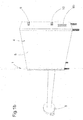
- Figures 1a and 1b show two perspective views of a preferred embodiment of the arrangement 1 of the present invention.
- the gas 2 and fluid 3 conduits have been included inside an enclosed chamber 4 whose outer casing 5 has two inlets 6a, 6b for air 2 and a tubed outlet 7 connected to an aspirator 8 that draws the air 2 from the aforesaid inlets 6 to the aforesaid outlet 7.
- the casing 5 of the chamber 4 also has an inlet 9 and outlet 10 provided for the fluid 3.
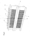
- Figure 2 shows a view of the interior of the chamber 4 without the outer casing 5, in which it can be observed that the fluid 3 flows through a plurality of vertical finned conduits 11 arranged in two rows, one upper and one lower, interconnected by means of collectors 12, which are also finned.
- the conduits 11 and collectors 12 of each row are integrated into supports 13 that allow circulation of the aspired gas 2 and, once covered with the outer casing, form the gas conduits 14 of the arrangement 1.
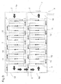
- FIG. 3 shows, the two rows of conduits 11 and their corresponding supports 13 are interconnected so as to form a circuit 15 of gas 2 and fluid 3 conduits from the inlet 6a to the outlet 7 connected to the aspirator 8.
- a second gas 3 inlet 6b has been provided that supplies the flow of the pipe 14 as it passes through the second row of fluid conduits 11. That second inlet 6b allows the heat-exchange performance to be optimised still further.
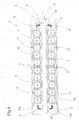
- Figure 4 shows a schematic plan view of the chamber 4 in which two independent circuits 15a, 15b of conduits 11, 14 for gas 2 and fluid 3 can be observed, arranged in a battery.
- the two circuits 15 share the same inlets 6a, 6b and outlet 7 for gas and, therefore, also the same aspirator 8.
- the flow of fluid 3 that exchanges heat can thus be increased and, therewith, the output of the exchanger, without this involving greater equipment energy consumption and cost.
- a balance pipe 16 is fitted inside the chamber 4.
- the hot water 3 could be residual water from industrial processes in which heat is generated, while in the case of a household it could be the water from the mains itself, which in the case of hot countries close to deserts habitually ranges between 40°C and 60°C, thereby making the sanitary use of such water 3 difficult and uncomfortable for purposes such as taking a bath, etc.
- a certain flow of water 3 is made to circulate through the finned pipes 11 of the arrangement 1 while the aspirator 8 draws in the ambient air 2 and takes it through the conduits 14 and to the outlet 7.
- the exchange of heat takes place inside the aforesaid conduits 14 for forced air 2, in which the aspired air 2 comes into contact under pressure with the outer surface of the finned pipes 11 that contain the hot water 3, absorbing its heat.
- the efficacy of the arrangement 1 of the present invention is surprisingly high, since it enables a large flow of water 3 cooled to 18°C to be obtained. Furthermore, this is achieved with a very simple design and very low energy consumption that allows savings of nearly 100% of the energy consumption of the conventional equipment that uses water refrigeration pumps.
- the equipment of the present invention can therefore have an arrangement 1 function and a climatiser 1 function.
- the hot water 3 generated in industry can be cooled without altering its composition in order to achieve values that allow it to be reused. That same industry could then take advantage of the warm air 2 obtained in order to climatise, for example, the offices zone.
- the water 3 from the mains can be cooled until it attains values that allow it to be used comfortably and without problems for sanitary purposes, while the warm air 2 that is generated can be put to other uses or expelled to the exterior.
- the arrangement 1 could be attached to a conventional refrigeration system. The user could thus benefit from the efficiency and energy saving of the equipment of the present invention.
- the arrangement 1 was used for cooling water 3 and heating air 2; as noted, however, said arrangement 1 could also be used for heating water 3 and cooling air 2.
- the user should have a supply of air 2, or any other gas, at a high preset temperature to supply the desired heat to said water 3.
- the energy required to heat said air or gas 2 could come from renewable sources.
Landscapes
- Engineering & Computer Science (AREA)
- Physics & Mathematics (AREA)
- Thermal Sciences (AREA)
- Mechanical Engineering (AREA)
- General Engineering & Computer Science (AREA)
- Heat-Exchange Devices With Radiators And Conduit Assemblies (AREA)
- Devices For Blowing Cold Air, Devices For Blowing Warm Air, And Means For Preventing Water Condensation In Air Conditioning Units (AREA)
- Air Filters, Heat-Exchange Apparatuses, And Housings Of Air-Conditioning Units (AREA)
Claims (12)
- Anordnung zum Austauschen von Wärme, die einen Wärmetauscher umfasst, der mindestens Folgendes aufweist: eine erste Rohrleitung (11), durch welche ein Fluid (3) zirkuliert, und Mittel zum Erzeugen einer kontinuierlichen Gasströmung (2), die die Wärme mit dem Fluid (3) austauscht, wobei der Wärmetauscher mindestens eine zweite Rohrleitung (14) aufweist, durch welche das Gas (2) zirkuliert, wobei die zweite Rohrleitung (14) in ihrem Inneren die erste Rohrleitung (11) trägt, durch welche das Fluid (3) zirkuliert, wobei die Mittel zum Erzeugen der kontinuierlichen Gasströmung einen Sauglüfter (8) aufweisen, dessen Eintrittsöffnung auf eine solche Weise mit der zweiten Rohrleitung (14) verbunden ist, dass das Gas (2) angesaugt und von einer Eintrittsöffnung (6a, 6b) durch die zweite Rohrleitung (14) zu einer Austrittsöffnung (7) geführt wird, dadurch gekennzeichnet, dass die Anordnung Folgendes aufweist: mehrere miteinander verbundene zweite Rohrleitungen, die die zweite Rohrleitung (14) bilden, durch welche das Gas (2) von der Eintrittsöffnung (6a, 6b) zu der Austrittsöffnung (7) zirkuliert, und mehrere miteinander verbundene Rohrleitungen (11), die die erste Rohrleitung bilden, durch welche das Fluid (3) zirkuliert, wobei die miteinander verbundenen Fluid-Rohrleitungen (11) durch das Innere der zweiten miteinander verbundenen Rohrleitungen (14) verlaufen, und dadurch, dass die Anordnung eine gekapselte Kammer (4) aufweist, die in ihrem Inneren die mehreren zweiten miteinander verbundenen Rohrleitungen (14) aufweist, die mindestens zwei als Batterie montierte unabhängige Gas-(2)-Kreise (15a, 15b) bilden, wobei die gekapselte Kammer (4) mindestens eine Gas-(2)-Eintrittsöffnung (6a), die die zweiten miteinander verbundenen Rohrleitungen (14) der beiden Kreise (15a, 15b) versorgt, und mindestens eine Gas-(2)-Austrittsöffnung (7) aufweist, die die zweiten miteinander verbundenen Rohrleitungen (14) der beiden Kreise (15a, 15b) mit der Eintrittsöffnung des Sauglüfters (8) verbindet.
- Anordnung nach Anspruch 1, dadurch gekennzeichnet, dass es sich bei dem Gas um Luft (2) handelt.
- Anordnung nach Anspruch 2, dadurch gekennzeichnet, dass es sich bei dem Fluid um eine Flüssigkeit (3) handelt.
- Anordnung nach Anspruch 2 oder 3, dadurch gekennzeichnet, dass es sich bei dem Fluid um Wasser (3) handelt.
- Anordnung nach einem der Ansprüche 1, 2 und 4, dadurch gekennzeichnet, dass sie Mittel zum Regeln der die zweite Rohrleitung (14) passierenden Gasströmung (2) aufweist.
- Anordnung nach einem der Ansprüche 1, 2, 4 und 5, dadurch gekennzeichnet, dass sie Mittel zum Regeln der die Rohrleitung (11) passierenden Fluid-(3)-Strömung aufweist.
- Anordnung nach einem der vorhergehenden Ansprüche, dadurch gekennzeichnet, dass sie Mittel zum Anfeuchten der Außenfläche der ersten Rohrleitung (11) während des Ansaugens des Gases (2) aufweist.
- Klimatisiervorrichtung, dadurch gekennzeichnet, dass sie eine Anordnung (1) nach Anspruch 2 aufweist.
- Klimatisiervorrichtung nach Anspruch 8, dadurch gekennzeichnet, dass es sich bei dem Fluid der Anordnung (1) um Wasser (3) handelt.
- Klimatisiervorrichtung nach Anspruch 9, dadurch gekennzeichnet, dass sie Mittel zum Erwärmen des durch die Anordnung (1) zirkulierenden Wassers (3) aufweist.
- Klimatisiervorrichtung nach Anspruch 9, dadurch gekennzeichnet, dass sie Mittel zum Kühlen des durch die Anordnung (1) zirkulierenden Wassers (3) aufweist.
- Klimatisiervorrichtung nach Anspruch 10 oder 11, dadurch gekennzeichnet, dass die zum Erwärmen oder Kühlen des Wassers (3) notwendige Energie aus emeuerbaren Quellen stammt.
Applications Claiming Priority (2)
| Application Number | Priority Date | Filing Date | Title |
|---|---|---|---|
| ES200600390A ES2284375B1 (es) | 2006-02-15 | 2006-02-15 | Intercambiador de calor y climatizador que comprende dicho intercambiador. |
| PCT/EP2007/051383 WO2007093590A1 (en) | 2006-02-15 | 2007-02-13 | Heat exchanger and climatiser that includes said exchanger |
Publications (2)
| Publication Number | Publication Date |
|---|---|
| EP1989498A1 EP1989498A1 (de) | 2008-11-12 |
| EP1989498B1 true EP1989498B1 (de) | 2010-03-10 |
Family
ID=38254959
Family Applications (1)
| Application Number | Title | Priority Date | Filing Date |
|---|---|---|---|
| EP07704555A Not-in-force EP1989498B1 (de) | 2006-02-15 | 2007-02-13 | Anordung zum wärmetauschen und der anordung enthaltendes klimaaggregat |
Country Status (5)
| Country | Link |
|---|---|
| EP (1) | EP1989498B1 (de) |
| AT (1) | ATE460631T1 (de) |
| DE (1) | DE602007005230D1 (de) |
| ES (1) | ES2284375B1 (de) |
| WO (1) | WO2007093590A1 (de) |
Families Citing this family (1)
| Publication number | Priority date | Publication date | Assignee | Title |
|---|---|---|---|---|
| CN113423235B (zh) * | 2021-05-11 | 2022-04-22 | 西安交通大学 | 一种用于机载电子设备的冷却系统 |
Citations (4)
| Publication number | Priority date | Publication date | Assignee | Title |
|---|---|---|---|---|
| FR589853A (fr) * | 1924-11-29 | 1925-06-06 | Olivet Et Mazars Sa Des Ets | Appareil moto-ventilateur à grand rayon d'action pour chauffage par pulsion d'air chaud |
| US2122256A (en) * | 1936-03-02 | 1938-06-28 | Charles H Leach | Heat exchange apparatus |
| GB547436A (en) * | 1940-02-29 | 1942-08-27 | Internat Anemostat Holding Com | Improvements in or relating to air heating and cooling apparatus |
| US20010017202A1 (en) * | 2000-02-25 | 2001-08-30 | Tetsuji Mitsumoto | Heat exchanger for easily polymerizing substance-containing gas provided with gas distributing plate |
Family Cites Families (6)
| Publication number | Priority date | Publication date | Assignee | Title |
|---|---|---|---|---|
| JPS59142379A (ja) | 1983-02-01 | 1984-08-15 | Mitsubishi Electric Corp | 冷風扇風機用熱交換器 |
| JPH09280755A (ja) * | 1996-04-18 | 1997-10-31 | Sanden Corp | 多管式熱交換器 |
| JPH109777A (ja) * | 1996-06-25 | 1998-01-16 | Sanden Corp | 多管式熱交換器および空調装置 |
| TW392835U (en) * | 1999-10-08 | 2000-06-01 | Paochang Electric Mfg Corp | High efficiency cooling device of cooling mechanism |
| US6964296B2 (en) * | 2001-02-07 | 2005-11-15 | Modine Manufacturing Company | Heat exchanger |
| JP2003240453A (ja) * | 2002-02-08 | 2003-08-27 | Mitsubishi Heavy Ind Ltd | 熱交換器 |
-
2006
- 2006-02-15 ES ES200600390A patent/ES2284375B1/es not_active Expired - Lifetime
-
2007
- 2007-02-13 DE DE602007005230T patent/DE602007005230D1/de active Active
- 2007-02-13 EP EP07704555A patent/EP1989498B1/de not_active Not-in-force
- 2007-02-13 WO PCT/EP2007/051383 patent/WO2007093590A1/en not_active Ceased
- 2007-02-13 AT AT07704555T patent/ATE460631T1/de not_active IP Right Cessation
Patent Citations (4)
| Publication number | Priority date | Publication date | Assignee | Title |
|---|---|---|---|---|
| FR589853A (fr) * | 1924-11-29 | 1925-06-06 | Olivet Et Mazars Sa Des Ets | Appareil moto-ventilateur à grand rayon d'action pour chauffage par pulsion d'air chaud |
| US2122256A (en) * | 1936-03-02 | 1938-06-28 | Charles H Leach | Heat exchange apparatus |
| GB547436A (en) * | 1940-02-29 | 1942-08-27 | Internat Anemostat Holding Com | Improvements in or relating to air heating and cooling apparatus |
| US20010017202A1 (en) * | 2000-02-25 | 2001-08-30 | Tetsuji Mitsumoto | Heat exchanger for easily polymerizing substance-containing gas provided with gas distributing plate |
Also Published As
| Publication number | Publication date |
|---|---|
| EP1989498A1 (de) | 2008-11-12 |
| DE602007005230D1 (de) | 2010-04-22 |
| ES2284375A1 (es) | 2007-11-01 |
| ATE460631T1 (de) | 2010-03-15 |
| ES2284375B1 (es) | 2008-10-16 |
| WO2007093590A1 (en) | 2007-08-23 |
Similar Documents
| Publication | Publication Date | Title |
|---|---|---|
| CN203432016U (zh) | 台式便携半导体制冷空调 | |
| CN203704150U (zh) | 一种双系统节能的机柜散热空调 | |
| CN107228436B (zh) | 一种基于太阳能和地冷的空调系统 | |
| CN103453604A (zh) | 一种太阳能空调系统 | |
| CN214333097U (zh) | 一种水冷空调系统及其空调器 | |
| CN101959388A (zh) | 一种带制冷剂循环换热的电信机柜及其冷却方法 | |
| CN201599988U (zh) | 半导体陶瓷芯片水冷环保中央空调器 | |
| CN201964523U (zh) | 一种室内供暖装置 | |
| CN101592410B (zh) | 五合一厨房能源回收利用系统 | |
| CN112594788A (zh) | 一种厨房空调结构及厨房空调器 | |
| KR20060093329A (ko) | 공기중의 열에너지를 이용한 열펌프식 온수기 | |
| CN201396979Y (zh) | 五合一厨房能源回收利用系统 | |
| RU2005111800A (ru) | Устройство для энергообеспечения помещений с использованием низкопотенциальных энергоносителей | |
| CN202063404U (zh) | 一种新高效实用型多功能半导体冷藏暖藏两用箱 | |
| CN212457074U (zh) | 一种带有水力集成模块的环境家居系统 | |
| CN107917459A (zh) | 一体式冷暖机组 | |
| EP1989498A1 (de) | Wärmetauscher und den wärmetauscher enthaltendes klimaaggregat | |
| CN216790291U (zh) | 一种厨房热水系统 | |
| CN213630742U (zh) | 全联供热泵除湿热水机组 | |
| CN214148180U (zh) | 一种建筑物空调氟水联合机组 | |
| CN202869114U (zh) | 一种新型简单高效多功能半导体冷藏暖藏两用箱 | |
| CN101963413A (zh) | 一种有冷媒输出的半导体加热式沐浴水箱 | |
| CN211476361U (zh) | 一种多功能空气源热泵系统 | |
| CN202392899U (zh) | 空调风柜及带有该风柜的空调系统 | |
| CN224266607U (zh) | 一种热交换模块及单元式两联供空调系统 |
Legal Events
| Date | Code | Title | Description |
|---|---|---|---|
| PUAI | Public reference made under article 153(3) epc to a published international application that has entered the european phase |
Free format text: ORIGINAL CODE: 0009012 |
|
| 17P | Request for examination filed |
Effective date: 20080909 |
|
| AK | Designated contracting states |
Kind code of ref document: A1 Designated state(s): AT BE BG CH CY CZ DE DK EE ES FI FR GB GR HU IE IS IT LI LT LU LV MC NL PL PT RO SE SI SK TR |
|
| 17Q | First examination report despatched |
Effective date: 20090115 |
|
| RTI1 | Title (correction) |
Free format text: ARRANGEMENT FOR EXCHANGING HEAT AND CLIMATISER THAT INCLUDES SAID ARRANGEMENT |
|
| GRAP | Despatch of communication of intention to grant a patent |
Free format text: ORIGINAL CODE: EPIDOSNIGR1 |
|
| DAX | Request for extension of the european patent (deleted) | ||
| GRAS | Grant fee paid |
Free format text: ORIGINAL CODE: EPIDOSNIGR3 |
|
| GRAA | (expected) grant |
Free format text: ORIGINAL CODE: 0009210 |
|
| AK | Designated contracting states |
Kind code of ref document: B1 Designated state(s): AT BE BG CH CY CZ DE DK EE ES FI FR GB GR HU IE IS IT LI LT LU LV MC NL PL PT RO SE SI SK TR |
|
| REG | Reference to a national code |
Ref country code: GB Ref legal event code: FG4D |
|
| REG | Reference to a national code |
Ref country code: CH Ref legal event code: EP |
|
| REG | Reference to a national code |
Ref country code: IE Ref legal event code: FG4D |
|
| REF | Corresponds to: |
Ref document number: 602007005230 Country of ref document: DE Date of ref document: 20100422 Kind code of ref document: P |
|
| REG | Reference to a national code |
Ref country code: NL Ref legal event code: VDEP Effective date: 20100310 |
|
| PG25 | Lapsed in a contracting state [announced via postgrant information from national office to epo] |
Ref country code: LT Free format text: LAPSE BECAUSE OF FAILURE TO SUBMIT A TRANSLATION OF THE DESCRIPTION OR TO PAY THE FEE WITHIN THE PRESCRIBED TIME-LIMIT Effective date: 20100310 |
|
| LTIE | Lt: invalidation of european patent or patent extension |
Effective date: 20100310 |
|
| PG25 | Lapsed in a contracting state [announced via postgrant information from national office to epo] |
Ref country code: FI Free format text: LAPSE BECAUSE OF FAILURE TO SUBMIT A TRANSLATION OF THE DESCRIPTION OR TO PAY THE FEE WITHIN THE PRESCRIBED TIME-LIMIT Effective date: 20100310 Ref country code: AT Free format text: LAPSE BECAUSE OF FAILURE TO SUBMIT A TRANSLATION OF THE DESCRIPTION OR TO PAY THE FEE WITHIN THE PRESCRIBED TIME-LIMIT Effective date: 20100310 Ref country code: SI Free format text: LAPSE BECAUSE OF FAILURE TO SUBMIT A TRANSLATION OF THE DESCRIPTION OR TO PAY THE FEE WITHIN THE PRESCRIBED TIME-LIMIT Effective date: 20100310 Ref country code: PL Free format text: LAPSE BECAUSE OF FAILURE TO SUBMIT A TRANSLATION OF THE DESCRIPTION OR TO PAY THE FEE WITHIN THE PRESCRIBED TIME-LIMIT Effective date: 20100310 Ref country code: LV Free format text: LAPSE BECAUSE OF FAILURE TO SUBMIT A TRANSLATION OF THE DESCRIPTION OR TO PAY THE FEE WITHIN THE PRESCRIBED TIME-LIMIT Effective date: 20100310 |
|
| PG25 | Lapsed in a contracting state [announced via postgrant information from national office to epo] |
Ref country code: ES Free format text: LAPSE BECAUSE OF FAILURE TO SUBMIT A TRANSLATION OF THE DESCRIPTION OR TO PAY THE FEE WITHIN THE PRESCRIBED TIME-LIMIT Effective date: 20100621 Ref country code: GR Free format text: LAPSE BECAUSE OF FAILURE TO SUBMIT A TRANSLATION OF THE DESCRIPTION OR TO PAY THE FEE WITHIN THE PRESCRIBED TIME-LIMIT Effective date: 20100611 Ref country code: NL Free format text: LAPSE BECAUSE OF FAILURE TO SUBMIT A TRANSLATION OF THE DESCRIPTION OR TO PAY THE FEE WITHIN THE PRESCRIBED TIME-LIMIT Effective date: 20100310 Ref country code: RO Free format text: LAPSE BECAUSE OF FAILURE TO SUBMIT A TRANSLATION OF THE DESCRIPTION OR TO PAY THE FEE WITHIN THE PRESCRIBED TIME-LIMIT Effective date: 20100310 Ref country code: SE Free format text: LAPSE BECAUSE OF FAILURE TO SUBMIT A TRANSLATION OF THE DESCRIPTION OR TO PAY THE FEE WITHIN THE PRESCRIBED TIME-LIMIT Effective date: 20100310 Ref country code: EE Free format text: LAPSE BECAUSE OF FAILURE TO SUBMIT A TRANSLATION OF THE DESCRIPTION OR TO PAY THE FEE WITHIN THE PRESCRIBED TIME-LIMIT Effective date: 20100310 Ref country code: CY Free format text: LAPSE BECAUSE OF FAILURE TO SUBMIT A TRANSLATION OF THE DESCRIPTION OR TO PAY THE FEE WITHIN THE PRESCRIBED TIME-LIMIT Effective date: 20100310 Ref country code: BE Free format text: LAPSE BECAUSE OF FAILURE TO SUBMIT A TRANSLATION OF THE DESCRIPTION OR TO PAY THE FEE WITHIN THE PRESCRIBED TIME-LIMIT Effective date: 20100310 |
|
| PG25 | Lapsed in a contracting state [announced via postgrant information from national office to epo] |
Ref country code: IS Free format text: LAPSE BECAUSE OF FAILURE TO SUBMIT A TRANSLATION OF THE DESCRIPTION OR TO PAY THE FEE WITHIN THE PRESCRIBED TIME-LIMIT Effective date: 20100710 Ref country code: CZ Free format text: LAPSE BECAUSE OF FAILURE TO SUBMIT A TRANSLATION OF THE DESCRIPTION OR TO PAY THE FEE WITHIN THE PRESCRIBED TIME-LIMIT Effective date: 20100310 Ref country code: BG Free format text: LAPSE BECAUSE OF FAILURE TO SUBMIT A TRANSLATION OF THE DESCRIPTION OR TO PAY THE FEE WITHIN THE PRESCRIBED TIME-LIMIT Effective date: 20100610 Ref country code: SK Free format text: LAPSE BECAUSE OF FAILURE TO SUBMIT A TRANSLATION OF THE DESCRIPTION OR TO PAY THE FEE WITHIN THE PRESCRIBED TIME-LIMIT Effective date: 20100310 |
|
| PLBE | No opposition filed within time limit |
Free format text: ORIGINAL CODE: 0009261 |
|
| STAA | Information on the status of an ep patent application or granted ep patent |
Free format text: STATUS: NO OPPOSITION FILED WITHIN TIME LIMIT |
|
| PG25 | Lapsed in a contracting state [announced via postgrant information from national office to epo] |
Ref country code: PT Free format text: LAPSE BECAUSE OF FAILURE TO SUBMIT A TRANSLATION OF THE DESCRIPTION OR TO PAY THE FEE WITHIN THE PRESCRIBED TIME-LIMIT Effective date: 20100712 Ref country code: DK Free format text: LAPSE BECAUSE OF FAILURE TO SUBMIT A TRANSLATION OF THE DESCRIPTION OR TO PAY THE FEE WITHIN THE PRESCRIBED TIME-LIMIT Effective date: 20100310 |
|
| 26N | No opposition filed |
Effective date: 20101213 |
|
| PG25 | Lapsed in a contracting state [announced via postgrant information from national office to epo] |
Ref country code: IT Free format text: LAPSE BECAUSE OF FAILURE TO SUBMIT A TRANSLATION OF THE DESCRIPTION OR TO PAY THE FEE WITHIN THE PRESCRIBED TIME-LIMIT Effective date: 20100310 |
|
| PG25 | Lapsed in a contracting state [announced via postgrant information from national office to epo] |
Ref country code: MC Free format text: LAPSE BECAUSE OF NON-PAYMENT OF DUE FEES Effective date: 20110228 |
|
| REG | Reference to a national code |
Ref country code: CH Ref legal event code: PL |
|
| GBPC | Gb: european patent ceased through non-payment of renewal fee |
Effective date: 20110213 |
|
| PG25 | Lapsed in a contracting state [announced via postgrant information from national office to epo] |
Ref country code: LI Free format text: LAPSE BECAUSE OF NON-PAYMENT OF DUE FEES Effective date: 20110228 Ref country code: CH Free format text: LAPSE BECAUSE OF NON-PAYMENT OF DUE FEES Effective date: 20110228 |
|
| REG | Reference to a national code |
Ref country code: FR Ref legal event code: ST Effective date: 20111102 |
|
| REG | Reference to a national code |
Ref country code: IE Ref legal event code: MM4A |
|
| PG25 | Lapsed in a contracting state [announced via postgrant information from national office to epo] |
Ref country code: IE Free format text: LAPSE BECAUSE OF NON-PAYMENT OF DUE FEES Effective date: 20110213 Ref country code: FR Free format text: LAPSE BECAUSE OF NON-PAYMENT OF DUE FEES Effective date: 20110228 |
|
| REG | Reference to a national code |
Ref country code: DE Ref legal event code: R119 Ref document number: 602007005230 Country of ref document: DE Effective date: 20110901 |
|
| PG25 | Lapsed in a contracting state [announced via postgrant information from national office to epo] |
Ref country code: GB Free format text: LAPSE BECAUSE OF NON-PAYMENT OF DUE FEES Effective date: 20110213 |
|
| PG25 | Lapsed in a contracting state [announced via postgrant information from national office to epo] |
Ref country code: LU Free format text: LAPSE BECAUSE OF NON-PAYMENT OF DUE FEES Effective date: 20110213 |
|
| PG25 | Lapsed in a contracting state [announced via postgrant information from national office to epo] |
Ref country code: DE Free format text: LAPSE BECAUSE OF NON-PAYMENT OF DUE FEES Effective date: 20110901 |
|
| PG25 | Lapsed in a contracting state [announced via postgrant information from national office to epo] |
Ref country code: TR Free format text: LAPSE BECAUSE OF FAILURE TO SUBMIT A TRANSLATION OF THE DESCRIPTION OR TO PAY THE FEE WITHIN THE PRESCRIBED TIME-LIMIT Effective date: 20100310 |
|
| PG25 | Lapsed in a contracting state [announced via postgrant information from national office to epo] |
Ref country code: HU Free format text: LAPSE BECAUSE OF FAILURE TO SUBMIT A TRANSLATION OF THE DESCRIPTION OR TO PAY THE FEE WITHIN THE PRESCRIBED TIME-LIMIT Effective date: 20100310 |