EP1990104A2 - Method and device for simultaneously cleaning a plurality of pipelines or pipeline systems - Google Patents
Method and device for simultaneously cleaning a plurality of pipelines or pipeline systems Download PDFInfo
- Publication number
- EP1990104A2 EP1990104A2 EP08103936A EP08103936A EP1990104A2 EP 1990104 A2 EP1990104 A2 EP 1990104A2 EP 08103936 A EP08103936 A EP 08103936A EP 08103936 A EP08103936 A EP 08103936A EP 1990104 A2 EP1990104 A2 EP 1990104A2
- Authority
- EP
- European Patent Office
- Prior art keywords
- cleaning
- cleaned
- cleaning medium
- flow
- partial
- Prior art date
- Legal status (The legal status is an assumption and is not a legal conclusion. Google has not performed a legal analysis and makes no representation as to the accuracy of the status listed.)
- Granted
Links
- 238000004140 cleaning Methods 0.000 title claims abstract description 94
- 238000000034 method Methods 0.000 title claims abstract description 31
- 239000007788 liquid Substances 0.000 claims abstract description 4
- 239000002253 acid Substances 0.000 claims description 5
- 230000001105 regulatory effect Effects 0.000 claims description 2
- 238000005259 measurement Methods 0.000 claims 2
- 238000009529 body temperature measurement Methods 0.000 claims 1
- 239000000243 solution Substances 0.000 description 5
- XLYOFNOQVPJJNP-UHFFFAOYSA-N water Chemical compound O XLYOFNOQVPJJNP-UHFFFAOYSA-N 0.000 description 5
- 238000010586 diagram Methods 0.000 description 3
- 230000000694 effects Effects 0.000 description 2
- 239000003513 alkali Substances 0.000 description 1
- 239000003518 caustics Substances 0.000 description 1
- 230000007423 decrease Effects 0.000 description 1
- 230000007812 deficiency Effects 0.000 description 1
- 238000009826 distribution Methods 0.000 description 1
- 238000002386 leaching Methods 0.000 description 1
- 238000004519 manufacturing process Methods 0.000 description 1
- 239000000463 material Substances 0.000 description 1
- 238000010926 purge Methods 0.000 description 1
- 238000000746 purification Methods 0.000 description 1
- 238000009420 retrofitting Methods 0.000 description 1
- 239000010865 sewage Substances 0.000 description 1
- 239000007921 spray Substances 0.000 description 1
Images

Classifications
-
- B—PERFORMING OPERATIONS; TRANSPORTING
- B08—CLEANING
- B08B—CLEANING IN GENERAL; PREVENTION OF FOULING IN GENERAL
- B08B9/00—Cleaning hollow articles by methods or apparatus specially adapted thereto
- B08B9/02—Cleaning pipes or tubes or systems of pipes or tubes
- B08B9/027—Cleaning the internal surfaces; Removal of blockages
- B08B9/032—Cleaning the internal surfaces; Removal of blockages by the mechanical action of a moving fluid, e.g. by flushing
- B08B9/0321—Cleaning the internal surfaces; Removal of blockages by the mechanical action of a moving fluid, e.g. by flushing using pressurised, pulsating or purging fluid
- B08B9/0325—Control mechanisms therefor
-
- B—PERFORMING OPERATIONS; TRANSPORTING
- B08—CLEANING
- B08B—CLEANING IN GENERAL; PREVENTION OF FOULING IN GENERAL
- B08B9/00—Cleaning hollow articles by methods or apparatus specially adapted thereto
- B08B9/02—Cleaning pipes or tubes or systems of pipes or tubes
- B08B9/027—Cleaning the internal surfaces; Removal of blockages
- B08B9/032—Cleaning the internal surfaces; Removal of blockages by the mechanical action of a moving fluid, e.g. by flushing
- B08B9/0321—Cleaning the internal surfaces; Removal of blockages by the mechanical action of a moving fluid, e.g. by flushing using pressurised, pulsating or purging fluid
- B08B9/0323—Arrangements specially designed for simultaneous and parallel cleaning of a plurality of conduits
Definitions
- the invention relates to a method for the simultaneous cleaning of a plurality of pipelines or piping systems, each with different line cross-sections, wherein the cleaning is carried out with a liquid cleaning medium, which is removed by means of a feed pump a collection and fed to the systems to be cleaned and a device for performing such a method.
- the first CIP systems supplied the cleaning media (temperature and concentration) in a fixed sequence and duration, which was determined by a program stored in the CIP system.
- the cleaning medium was pumped through the system to be cleaned during the cleaning process, but then passed into the sewage system. This process is referred to as "lost" cleaning because the cleaning medium is not reused.
- the so-called CIP circulation cleaning was developed with a "stacking" of cleaning solutions, whereby the cleaning media (usually caustic and / or acid solutions) return to the CIP via lines and are reused there, as the cleaning power is sufficient.
- the invention is therefore based on the object, the above-mentioned and previously described method and a corresponding device for cleaning of lines in such a way and further, that the amount of cleaning medium required and the cleaning time can be minimized without affecting the aseptic conditions.
- the object is achieved according to a first alternative in that the cleaning medium flow is supplied to the first system to be cleaned and is divided after leaving the first system to be cleaned into two partial streams, of which a partial flow for cleaning the second or further system is used and the other partial flow is returned to the sump.
- the object is achieved in that a cleaning medium stream is first supplied to the second or further system to be cleaned and then divided into partial streams, one of which in turn is mixed with the second partial flow and the other is returned to the sump.
- the cleaning medium stream is first divided into two partial streams, of which the first is returned to the collecting container and the second cleaning medium initially in streams one of which is supplied to the second or further system to be cleaned and the other to the collecting container.
- the alternative modes of operation described are particularly useful since they can be achieved alternately without constructive extension or circuit complexity.
- the second or further system to be cleaned is associated with a delivery pump, whose direction of rotation for selecting the two alternative methods described must merely be reversed.
- a corresponding device is characterized in that a second or further system to be cleaned is associated with a feed pump whose speed and direction of rotation for determining or regulating the cleaning process can be changed, that the line for the first partial flow is designed as Druchhalteaji and in that a throttle valve is arranged in the return line of the partial flows.
- the rotational speed of this pump and thus the volume flow of the cleaning medium can be varied in both directions in order to achieve an optimum cleaning effect.
- the second or further system to be cleaned associated pump can be used both for conveying the cleaning medium and for conveying the product. This is particularly advantageous because - vice versa - especially at the retrofitting of a device according to the invention an existing pump can be used for the cleaning process with.
- control of the flow rate of cleaning medium via the speed control of the two pumps in CIP system and the system to be cleaned.
- the cleaning medium stream is first divided into two partial streams before entering the first system to be cleaned, of which the first is returned to the collecting container and the second is supplied to the first system to be cleaned.
- the cleaning medium stream is first divided into two partial streams before entering the first system to be cleaned, of which the first is returned to the collecting container and the second is supplied to the first system to be cleaned.
- By reducing the first partial flow it is possible to influence the temperature, concentration or amount of the cleaning medium for the main flow to be carried out for the purification of the systems.
- the inventive method is in this case particularly economical with respect to the cleaning medium, since the branched first partial flow can (re) be used in a lack of cleaning medium in the systems to be cleaned for refilling the cleaning system.
- the clearing (Lauge- / acid concentration) of the cleaning medium is adjustable.
- the CIP system can be equipped with several collection tanks for different cleaning media. This is sufficiently known from the prior art and should therefore apply correspondingly to the method according to the invention or the corresponding device, without it being necessary to refer to it in detail.
- the device according to the invention can also be used, in particular, when the line cross sections of the systems to be cleaned are of different sizes. Due to the line circuit according to the invention a simultaneous cleaning of two or more systems with different skillssmengen or nominal sizes is independent of the delivery rate of the feed pump of the CIP system possible.
- the device according to the invention preferably has sensors for measuring the volume flows and / or for measuring the temperature or conductivity.
- 'conductivity' is meant the acid / alkali concentration of the cleaning medium.
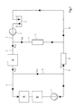
- Fig. 1 shows how a cleaning medium is conveyed by the CIP system with at least one sump 1 and a feed pump 2 via the flow line 3 in the direction of subsystem A. Via a bypass 4, a partial flow TS1 is returned to the return line to the CIP system. This current is used in case of medium deficiency in the subsystems for refilling.
- Partial flow TS3 is returned via line 8, which serves as a bypass here, to line 6 between subsystem A and subsystem B (internal circuit).
- Partial flow TS4 flows back via a throttle 12 to the CIP system. This amount, which leaves the subsystems A, B and B ', decides on the amount of feed of fresh cleaning medium in the subsystems A, B and B' from the CIP system.
- the remaining partial flow TS2 passes via a line 5 in the subsystem A to be cleaned and from there as partial flow TS2 'via a line 6 on in the subsystem B. Dashed indicates that there are in addition to the subsystem B also to be cleaned subsystems B' can.
- feed pump 7 provides the necessary flow of the cleaning medium, supported by the feed pump 2 of the CIP system.
- the substream TS2 'before entering the subsystem B is combined with the further substream TS3 already passed through this system, which is led back into the line 6 via a line 8.
- a previously separated amount of the cleaning medium is supplied as a partial stream TS4 again to the collection container 1 via the lines 9 and 10.
- a pressure holding unit 11 and in line 12 a throttle valve are provided in the line 4.
- the two subsystems A and B can have different sizes. Due to the fact that the part of the system A already left partial flow TS2 'may enter the subsystem B or B', the reverse case is excluded, it is reliably avoided that in the lines with a larger nominal size of the subsystems B or B. 'lumpy material located in the subsystem A can promote and lead there to blockages.
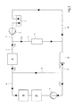
- the partial flow TS2 leaves the subsystem A to be cleaned as partial flow TS2 'and is conducted via the line 8 and then again divided into the partial flows TS3 * and TS4 *.
- the partial flow TS3 * is used to clean the subsystems B (or before already used B ') and the partial flow TS4 * fed back to the sump 1.
- the substream TS3 * is mixed back into the substream TS2' via the line 6.
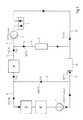
- Fig. 3 and 4 are identical in content to the Fig. 1 and 2 However, for better understanding, for example, the flow rates with the unit volume / time (m 3 / h) are also shown.
- the cleaning medium leaves in the example shown (both alternatives), the feed pump 2 of the CIP system with 7 m 3 / h and is further promoted after the first division in 2 m 3 / h as partial flow TS1 and 5 m 3 / h as partial flow TS2.
- a further partial flow TS3 (20 m 3 / h) of the cleaning medium which has already passed through the subsystems B and possibly B', initiated, so that a total flow of 25 m 3 / h, which is introduced into the subsystems B and possibly B '.
- the feed pump 7 ensures for a constant delivery of the illustrated example 25 m 3 / h.
- the delivery flow below the feed pump 7 is divided into the substreams TS3 (20 m 3 / h) and TS4 (5 m 3 / h), wherein the substream TS4 (5 m 3 / h) together with the substream TS1 (FIG. 2 m 3 / h) with an amount of cleaning medium of 7 m 3 / h to the CIP system dissipated.
Landscapes
- Engineering & Computer Science (AREA)
- Mechanical Engineering (AREA)
- Cleaning In General (AREA)
- Cleaning By Liquid Or Steam (AREA)
Abstract
Description
Die Erfindung betrifft ein Verfahren zum gleichzeitigen Reinigen mehrerer Rohrleitungen oder Rohrleitungssysteme insbesondere mit jeweils unterschiedlichen Leitungsquerschnitten, wobei die Reinigung mit einem flüssigen Reinigungsmedium erfolgt, welches mittels einer Förderpumpe einem Sammelbehälter entnommen und den zu reinigenden Systemen zugeführt wird sowie eine Vorrichtung zur Durchführung eines solchen Verfahrens.The invention relates to a method for the simultaneous cleaning of a plurality of pipelines or piping systems, each with different line cross-sections, wherein the cleaning is carried out with a liquid cleaning medium, which is removed by means of a feed pump a collection and fed to the systems to be cleaned and a device for performing such a method.
Dabei bedient man sich den bekannten Verfahren des 'CIP', nämlich des "Cleaning in Place". Die CIP zur Reinigung von Leitungssystemen sind schon seit mehreren Jahrzehnten Stand der Technik bei der Reinigung von beispielsweise Lebensmittelabfüllanlagen. Wenn im folgenden von Lebensmittelabfüllanlagen oder kurz Füllmaschinen die Rede ist, soll sich die vorliegende Erfindung keinesfalls auf nur solche Maschinen beschränken, damit sich mit dem erfindungsgemäßen Verfahren beliebige Rohrleitungen bzw. Rohrleitungssysteme reinigen lassen.It uses the well-known method of 'CIP', namely the "cleaning in place". The CIP for the cleaning of piping systems have been state of the art in the cleaning of, for example, food filling plants for several decades. If in the following of food filling plants or short filling machines is mentioned, the present invention should not be limited to only such machines, so that can be cleaned with the inventive method any piping or piping systems.
Kennzeichnend ist dabei, dass von einer dezentralen Versorgungsanlage (kurz: CIP-Anlage) unterschiedliche Reinigungsmedien angemischt, temperiert und bevorratet werden, um dann bei einer Reinigungsanforderung das angeforderte Medium über eine Pumpe und ein Rohrleitungssystem zum zu reinigenden System zu leiten.It is characteristic that different cleaning media are mixed, tempered and stored by a decentralized supply system (in short: CIP system), in order then to guide the requested medium via a pump and a piping system to the system to be cleaned during a cleaning request.
Erste CIP-Anlagen lieferten auf Anfrage des zu reinigenden Systems die Reinigungsmedien (Temperatur und Konzentration) in einer festgelegten Reihenfolge und Dauer, welche durch ein in der CIP-Anlage hinterlegtes Programm bestimmt wurde.At the request of the system to be cleaned, the first CIP systems supplied the cleaning media (temperature and concentration) in a fixed sequence and duration, which was determined by a program stored in the CIP system.
Das Reinigungsmedium wurde während des Reinigungsvorganges durch das zu reinigende System gepumpt, danach jedoch in die Kanalisation geleitet. Dieses Verfahren wird als "verlorene" Reinigung bezeichnet, da das Reinigungsmedium nicht wieder verwendet wird.The cleaning medium was pumped through the system to be cleaned during the cleaning process, but then passed into the sewage system. This process is referred to as "lost" cleaning because the cleaning medium is not reused.
Zum Erreichen umweltschonender und sparsamer Produktionsprozesse wurde die so genannte CIP-Umlauf-Reinigung mit einer "Stapelung" von Reinigungslösungen entwickelt, wobei die Reinigungsmedien (üblicherweise Lauge- und/ oder Säurelösungen) über Leitungen zurück zur CIP gelangen und dort so lange wieder verwendet werden, wie die Reinigungskraft ausreicht.To achieve environmentally friendly and economical production processes, the so-called CIP circulation cleaning was developed with a "stacking" of cleaning solutions, whereby the cleaning media (usually caustic and / or acid solutions) return to the CIP via lines and are reused there, as the cleaning power is sufficient.
Die bekannten Verfahren der CIP-Anlage sind jedoch verbesserungswürdig:
- Die Strömungsgeschwindigkeit (Mechanik) der bereit gestellten Reinigungslösung ist abhängig von der Kapazität der CIP Pumpe, der Dimensionierung der Zuführleitung und der Leitungslänge zwischen CIP - Anlage und Abfüllmaschine. Daher werden in der Praxis Strömungsmengen zwischen 10 und 15 m3/h verwendet.
- Dieser strömungsmechanische Faktor beeinflusst das Reinigungsergebnis stark, deshalb ist in Abhängigkeit von den in Abfüllmaschinen verwendeten Tankgrößen und Rohrleitungsquerschnitten die bereitgestellte Menge oft zu gering und ein zufrieden stellendes Reinigungsergebnis nur über eine lange Reinigungsdauer zu erreichen, da die Strömungsgeschwindigkeit (und damit auch die Reinigungswirkung) bei großen Durchmessern stark sinkt.
- Oft werden Sprühbälle in Tanks verwendet, welche mehr mechanische Reinigungskraft auf die Tankoberflächen ausüben sollen. Diese Lösung birgt jedoch aseptische Risiken und kann bei so genannten Umkehrreinigungen (Umkehr der Strömungsrichtung bei der Reinigung) nicht eingesetzt werden, da die Gefahr besteht, dass stückige Produkte nicht vollständig entfernt werden.
- Prinzipiell kann über ein Leitungssystem nur ein Füllsystem gleichzeitig gereinigt werden, es sei denn, zwei Abfüllmaschinen durchlaufen dieselben Reinigungsschritte simultan. Sind jedoch zwei Füllsysteme für unterschiedliche Produkte ausgelegt (hier Wasser und Produkte mit Stücken), besteht die Gefahr, dass in das Füllsystem, welches für Wasser (kleiner) dimensioniert ist, Stücke aus dem anderen Füllsystem geraten und dieses verstopfen.
- Zudem werden bei dem größer dimensionierten Füllsystem höher Strömungsgeschwindigkeiten benötigt als bei dem Wasser-Füllsystem, um in der gleichen zeit ein ähnliches Reinigungsergebnis zu erreichen.
- Daher ist es bisher bei der Verwendung dieser zwei unterschiedlichen Füllsysteme notwendig, zwei separate CIP-Leitungen mit zwei separaten Pumpen anzuschließen, um die Systeme produktangepasst zeitgleich reinigen zu können.
- The flow rate (mechanics) of the cleaning solution provided depends on the capacity of the CIP pump, the dimensioning of the feed line and the length of the cable between the CIP system and the filling machine. Therefore, in practice, flow rates between 10 and 15 m 3 / h are used.
- This flow-mechanical factor strongly influences the cleaning result, therefore it depends on the tank sizes used in filling machines and Pipe cross sections the amount provided often too low and to achieve a satisfactory cleaning result only over a long cleaning time, since the flow rate (and thus also the cleaning effect) decreases greatly with large diameters.
- Often spray balls are used in tanks, which are to exert more mechanical cleaning power on the tank surfaces. However, this solution has aseptic risks and can not be used in so-called reverse cleaning (reversal of the direction of flow during cleaning), since there is a risk that lumpy products will not be completely removed.
- In principle, only one filling system can be cleaned simultaneously via a line system, unless two filling machines go through the same cleaning steps simultaneously. If, however, two filling systems are designed for different products (here water and products with pieces), there is a risk that the filling system, which is dimensioned for water (smaller), will cause pieces to come from the other filling system and clog it up.
- In addition, flow velocities are required in the larger-sized filling system higher than in the water filling system, in order to achieve a similar cleaning result in the same time.
- Therefore, it has been necessary in the use of these two different filling systems, two connect separate CIP lines with two separate pumps to clean the systems at the same time while being product-adapted.
Der Erfindung liegt daher die Aufgabe zugrunde, das eingangs genannte und zuvor näher beschriebene Verfahren sowie eine entsprechende Vorrichtung zum Reinigen von Leitungen so auszugestalten und weiterzubilden, dass die Menge des benötigten Reinigungsmediums und die Reinigungszeit ohne Beeinträchtigung der aseptischen Verhältnisse minimiert werden können.The invention is therefore based on the object, the above-mentioned and previously described method and a corresponding device for cleaning of lines in such a way and further, that the amount of cleaning medium required and the cleaning time can be minimized without affecting the aseptic conditions.
Hinsichtlich des Verfahrens wird die Aufgabe gemäß einer ersten Alternative dadurch gelöst, dass der Reinigungsmediumstrom dem ersten zu reinigenden System zugeführt wird und nach dem Verlassen des ersten zu reinigenden Systems in zwei Teilströme aufgeteilt wird, von denen ein Teilstrom zum Reinigen des zweiten bzw. weiteren Systems verwendet wird und der andere Teilstrom wieder dem Sammelbehälter zugeführt wird.With regard to the method, the object is achieved according to a first alternative in that the cleaning medium flow is supplied to the first system to be cleaned and is divided after leaving the first system to be cleaned into two partial streams, of which a partial flow for cleaning the second or further system is used and the other partial flow is returned to the sump.
Alternativ erfolgt die Lösung der Aufgabe dadurch, dass ein Reinigungsmediumstrom zunächst dem zweiten bzw. weiteren zu reinigenden System zugeführt wird und danach in Teilströme aufgeteilt wird, von denen einer wiederum den zweiten Teilstrom beigemischt wird und der andere wieder dem Sammelbehälter zugeführt wird.Alternatively, the object is achieved in that a cleaning medium stream is first supplied to the second or further system to be cleaned and then divided into partial streams, one of which in turn is mixed with the second partial flow and the other is returned to the sump.
Weiterhin ist vorgesehen, dass der Reinigungsmediumstrom zunächst in zwei Teilströme aufgeteilt wird, von denen der erste wieder dem Sammelbehälter zugeführt wird und der zweite Reinigungsmediumstrom zunächst in Teilströme aufgeteilt wird, von denen der eine dem zweiten bzw. weiteren zu reinigenden System und der andere wieder dem Sammelbehälter zugeführt wird.It is further provided that the cleaning medium stream is first divided into two partial streams, of which the first is returned to the collecting container and the second cleaning medium initially in streams one of which is supplied to the second or further system to be cleaned and the other to the collecting container.
Die beschriebenen alternativen Betriebsweisen sind besonders zweckmäßig, da sie abwechselnd ohne konstruktive Erweiterung oder schaltungstechnischen Aufwand erreichbar sind. Denn in weiterer Ausgestaltung der Erfindung ist dem zweiten bzw. weiteren zu reinigenden System eine Förderpumpe zugeordnet, deren Drehrichtung zur Auswahl der beiden beschriebenen alternativen Verfahren lediglich umgekehrt werden muss.The alternative modes of operation described are particularly useful since they can be achieved alternately without constructive extension or circuit complexity. For in a further embodiment of the invention, the second or further system to be cleaned is associated with a delivery pump, whose direction of rotation for selecting the two alternative methods described must merely be reversed.
Eine entsprechende erfindungsgemäße vorrichtung zeichnet sich dadurch aus, dass eine dem zweiten bzw. weiteren zu reinigenden System eine Förderpumpe zugeordnet ist, deren Drehzahl und Drehrichtung zur Bestimmung bzw. Regelung des Reinigungsverfahrens veränderbar sind, dass die Leitung für den ersten Teilstrom als Druchhalteeinheit ausgeführt ist und dass in der Rücklaufleitung der Teilströme ein Drosselventil angeordnet ist.A corresponding device according to the invention is characterized in that a second or further system to be cleaned is associated with a feed pump whose speed and direction of rotation for determining or regulating the cleaning process can be changed, that the line for the first partial flow is designed as Druchhalteeinheit and in that a throttle valve is arranged in the return line of the partial flows.
Gemäß einer weiteren bevorzugten Lehre der Erfindung ist die Drehzahl dieser Pumpe und damit der Volumenstrom des Reinigungsmediums in beiden Richtungen veränderbar, um eine optimale Reinigungswirkung erzielen zu können.According to a further preferred teaching of the invention, the rotational speed of this pump and thus the volume flow of the cleaning medium can be varied in both directions in order to achieve an optimum cleaning effect.
Besonders zweckmäßig ist es, dass die den zweiten bzw. weiteren zu reinigenden System zugeordnete Förderpumpe sowohl zum Fördern des Reinigungsmediums als auch zum Fördern des Produktes genutzt werden kann. Dies ist besonders vorteilhaft, da - umgekehrt - insbesondere bei der Nachrüstung einer erfindungsgemäßen Vorrichtung eine bereits vorhandene Förderpumpe für den Reinigungsprozess mit benutzt werden kann.It is particularly expedient that the second or further system to be cleaned associated pump can be used both for conveying the cleaning medium and for conveying the product. This is particularly advantageous because - vice versa - especially at the retrofitting of a device according to the invention an existing pump can be used for the cleaning process with.
zweckmäßigerweise erfolgt die Regelung der Durchflussmenge an Reinigungsmedium über die Drehzahlregelung der beiden Pumpen in CIP-Anlage und dem zu reinigenden System.Advantageously, the control of the flow rate of cleaning medium via the speed control of the two pumps in CIP system and the system to be cleaned.
Eine weitere Lehre der Erfindung sieht vor, dass der Reinigungsmediumstrom vor Eintritt in das erste zu reinigende System zunächst in zwei Teilströme aufgeteilt wird, von denen der erste in den Sammelbehälter zurückgeführt wird und der zweite dem ersten zu reinigenden System zugeführt wird. Hier entsteht also ein direkter Kreislauf des Reinigungsmediums. Durch Reduktion des ersten Teilstromes ist eine Beeinflussung der Temperatur, Konzentration oder Menge des Reinigungsmediums für den die Reinigung der Systeme durchzuführenden Hauptstrom möglich.Another teaching of the invention provides that the cleaning medium stream is first divided into two partial streams before entering the first system to be cleaned, of which the first is returned to the collecting container and the second is supplied to the first system to be cleaned. Here, therefore, creates a direct circulation of the cleaning medium. By reducing the first partial flow, it is possible to influence the temperature, concentration or amount of the cleaning medium for the main flow to be carried out for the purification of the systems.
Das erfindungsgemäße Verfahren ist in diesem Fall besonders sparsam hinsichtlich des Reinigungsmediums, da der abgezweigte erste Teilstrom bei einem Mangel an Reinigungsmedium in den zu reinigenden Systemen zum Nachfüllen des Reinigungssystems (wieder-)verwendet werden kann.The inventive method is in this case particularly economical with respect to the cleaning medium, since the branched first partial flow can (re) be used in a lack of cleaning medium in the systems to be cleaned for refilling the cleaning system.
Zweckmäßigerweise ist die Aufschärfung (Lauge-/Säurekonzentration) des Reinigungsmediums regelbar.Appropriately, the clearing (Lauge- / acid concentration) of the cleaning medium is adjustable.
Es versteht sich, dass die CIP-Anlage mit mehreren Sammelbehältern für unterschiedliche Reinigungsmedien ausgestattet sein kann. Dies ist aus dem Stand der Technik hinreichend bekannt und soll daher entsprechend für das erfindungsgemäße Verfahren bzw. die entsprechende Vorrichtung gelten, ohne dass darauf im einzelnen hingewiesen werden müsste.It is understood that the CIP system can be equipped with several collection tanks for different cleaning media. This is sufficiently known from the prior art and should therefore apply correspondingly to the method according to the invention or the corresponding device, without it being necessary to refer to it in detail.
Die erfindungsgemäße Vorrichtung lässt sich auch und insbesondere dann einsetzen, wenn die Leitungsquerschnitte der zu reinigenden Systeme unterschiedlich groß ausgebildet sind. Durch die erfindungsgemäße Leitungsschaltung ist eine simultane Reinigung von zwei oder mehreren Systemen mit unterschiedlichen Durchfiussmengen oder Nennweiten unabhängig von der Förderleistung der Förderpumpe der CIP-Anlage möglich.The device according to the invention can also be used, in particular, when the line cross sections of the systems to be cleaned are of different sizes. Due to the line circuit according to the invention a simultaneous cleaning of two or more systems with different Durchfiussmengen or nominal sizes is independent of the delivery rate of the feed pump of the CIP system possible.
Vorzugsweise weist die erfindungsgemäße Vorrichtung Sensoren zur Messung der volumenströme und/oder zur Temperatur- bzw. Leitwertmessung auf. Unter 'Leitwert' versteht man die Säure-/Laugenkonzentration des Reinigungsmediums.The device according to the invention preferably has sensors for measuring the volume flows and / or for measuring the temperature or conductivity. By 'conductivity' is meant the acid / alkali concentration of the cleaning medium.
Erfindungsgemäß ergeben sich folgende Vorteile:
- Höhere mechanische Reinigungskraft bei reduziertem Druck
- Weitgehende Unabhängigkeit von der Menge des bereitgestellten CIP-Reinigungsmediums
- Unabhängigkeit von der Massenträgheit des CIP-Reinigungsmediums in der Leitung zwischen CIP-Anlage und Füllmaschine
- Vermeidung von Druckschlägen bei Ventilstellungswechseln oder Umkehr der Fließrichtung
- Reinigungsmedium aus dem System mit der großen Nennweite gelangt dabei nicht in das System mit den kleinen Nennweiten
- Gleichzeitige Nutzung der Pumpe als Reinigungs- und aseptische Produktförderpumpe
- Automatische Temperatureinstellung und Mediumnachführung (Lauge-/ Säurekonzentration in den Reinigungssystemen)
- Durchflussregelung über Pumpendrehzahlregelung
- Higher mechanical cleaning power at reduced pressure
- Substantial independence from the amount of CIP cleaning medium provided
- Independence from the inertia of the CIP cleaning medium in the line between the CIP system and the filling machine
- Avoidance of pressure surges when changing valve positions or reversing the direction of flow
- Cleaning medium from the system with the large nominal diameter does not enter the system with the small nominal diameters
- Simultaneous use of the pump as a cleaning and aseptic product feed pump
- Automatic temperature adjustment and medium tracking (leaching / acid concentration in the cleaning systems)
- Flow control via pump speed control
Die Erfindung wird nachfolgend anhand einer lediglich vorteilhafte Ausführungsbeispiele darstellenden Zeichnung näher erläutert. In der Zeichnung zeigen:
- Fig. 1
- das Funktionsprinzip des erfindungsgemäßen Verfahrens in einem prinzipiellen Fließschema (erste Alternative),
- Fig. 2
- das Funktionsprinzip des erfindungsgemäßen Verfahrens in einem prinzipiellen Fließschema (zweite Alternative),
- Fig. 3
- das Fließschema aus
Fig. 1 , ergänzt um beispielhafte Durchflussmengen und - Fig. 4
- das Fließschema aus
Fig. 2 , ergänzt um beispielhafte Durchflussmengen.
- Fig. 1
- the functional principle of the process according to the invention in a schematic flow diagram (first alternative),
- Fig. 2
- the functional principle of the process according to the invention in a schematic flow diagram (second alternative),
- Fig. 3
- the flowchart
Fig. 1 , supplemented by exemplary flow rates and - Fig. 4
- the flowchart
Fig. 2 , supplemented by exemplary flow rates.
Es sei darauf hingewiesen, dass in sämtliche Figuren die Leitungen lediglich als Linien dargestellt sind, wobei die Pfeile die Fließrichtung des Reinigungsmediums angeben.It should be noted that in all figures, the lines are shown only as lines, the arrows indicate the direction of flow of the cleaning medium.
Teilstrom TS3 wird über die Leitung 8, die hier als Bypass dient, an die Leitung 6 zwischen Teilsystem A und Teilsystem B zurückgeführt (interner Kreislauf). Teilstrom TS4 fließt über eine Drossel 12 zur CIP-Anlage zurück. Diese Menge, welche die Teilsysteme A, B bzw. B' verlässt, entscheidet über die Menge an Zulauf von frischem Reinigungsmedium in die Teilsysteme A, B bzw. B' aus der CIP-Anlage. Der verbleibende Teilstrom TS2 gelangt über eine Leitung 5 in das zu reinigende Teilsystem A und von dort als Teilstrom TS2' über eine Leitung 6 weiter in das Teilsystem B. Gestrichelt ist angedeutet, dass es neben dem Teilsystem B auch weitere zu reinigende Teilsysteme B' geben kann. Eine im Bereich der Teilsysteme B, B' angeordnete Förderpumpe 7 sorgt für den nötigen Durchfluss des Reinigungsmediums, unterstützt von der Förderpumpe 2 der CIP-Anlage. Dieser Hauptreinigungstrom TS2' wird über die eingebaute Förderpumpe 7 beschleunigt oder verzögert und ein weiteres Mal geteilt (Teilströme TS3 und TS4).Partial flow TS3 is returned via
Im ersten Ausführungsbeispiel nach
Es ist schnell ersichtlich, dass die beiden Teilsysteme A und B verschieden große Nennweiten aufweisen können. Aufgrund der Tatsache, dass der das Teilsystem A bereits verlassene Teilstrom TS2' zwar in das Teilsystem B bzw. B' gelangen kann, der umgekehrte Fall jedoch ausgeschlossen ist, wird zuverlässig vermieden, dass sich in den Leitungen mit größerer Nennweite der Teilsysteme B oder B' befindliches stückiges Material in das Teilsystem A fördern lässt und dort zu Verstopfungen führen kann.It is easy to see that the two subsystems A and B can have different sizes. Due to the fact that the part of the system A already left partial flow TS2 'may enter the subsystem B or B', the reverse case is excluded, it is reliably avoided that in the lines with a larger nominal size of the subsystems B or B. 'lumpy material located in the subsystem A can promote and lead there to blockages.
Gleiches gilt für die alternative Betriebsweise, welche in
Nach dem Verlassen der zu reinigende Teilsysteme B bzw. B' wird der Teilstrom TS3* über die Leitung 6 wieder dem Teilstrom TS2' zugemischt.After leaving the subsystems B or B 'to be cleaned, the substream TS3 * is mixed back into the substream TS2' via the
Durch Vergleich der beiden Prinzipfließbilder aus
Die
Das Reinigungsmedium verlässt im dargestellten Beispiel (beide Alternativen) die Förderpumpe 2 der CIP-Anlage mit 7 m3/h und wird nach der ersten Aufteilung in 2 m3/h als Teilstrom TS1 und 5 m3/h als Teilstrom TS2 weitergefördert.The cleaning medium leaves in the example shown (both alternatives), the
Bei dem Fließschema gemäß
Wie bereits erwähnt, wird der Förderstrom unterhalb der Förderpumpe 7 in die Teilströme TS3 (20 m3/h) und TS4 (5 m3/h) aufgeteilt, wobei der Teilstrom TS4 (5 m3/h) gemeinsam mit dem Teilstrom TS1 (2 m3/h) mit einer Menge an Reinigungsmedium von 7 m3/h an die CIP-Anlage abgeführt.As already mentioned, the delivery flow below the
Anders ist dies in der alternativen Darstellung gemäß
In beiden
Claims (15)
dadurch gekennzeichnet, dass ein Reinigungsmediumstrom (TS2) dem ersten zu reinigenden System (A) zugeführt wird und nach dem Verlassen des ersten zu reinigenden Systems (A) als Reinigungsmediumstrom (TS2') in zwei Teilströme aufgeteilt wird, von denen ein Teilstrom zum Reinigen des zweiten bzw. weiteren Systems (B, B') verwendet wird und der andere Teilstrom wieder dem Sammelbehälter (1) zugeführt wird.Method for the simultaneous cleaning of several pipes or piping systems (A, B and possibly B '), in particular with different line cross sections, wherein the cleaning takes place with a liquid cleaning medium, which by means of a feed pump (2) a collecting container (1) and taken to cleaning systems (A, B, B ') is supplied,
characterized in that a cleaning medium flow (TS2) is supplied to the first system (A) to be cleaned and, after leaving the first system (A) to be cleaned, is divided as a cleaning medium flow (TS2 ') into two partial flows, of which a partial flow for cleaning the second or further system (B, B ') is used and the other partial flow is returned to the collecting container (1).
dadurch gekennzeichnet, dass der Reinigungsmediumstrom (TS2') zunächst dem zweiten bzw. weiteren zu reinigenden System (B, B') zugeführt wird und erst danach in Teilströme (TS3 und TS4) aufgeteilt wird, von denen der Teilstrom (TS3) dem zweiten Teilstrom (TS2') beigemischt wird und der andere Teilstrom (TS4) wieder dem Sammelbehälter (1) zugeführt wird.Method for the simultaneous cleaning of several pipes or piping systems (A, B and possibly B '), in particular with different line cross sections, wherein the cleaning takes place with a liquid cleaning medium, which by means of a feed pump (2) a collecting container (1) and taken to cleaning systems (A, B, B ') is supplied,
characterized in that the cleaning medium flow (TS2 ') is first supplied to the second or further system (B, B') to be cleaned and only then divided into partial flows (TS3 and TS4), of which the partial flow (TS3) the second partial flow (TS2 ') is added and the other partial flow (TS4) is returned to the collecting container (1).
dadurch gekennzeichnet, dass der Reinigungsmediumstrom (TS2') zunächst in Teilströme (TS3*) und TS4*) aufgeteilt wird, von denen der Teilstrom (TS3*) dem zweiten bzw. weiteren zu reinigenden System (B', B) zugeführt wird und der andere Teilstrom (TS4*) wieder dem Sammelbehälter (1) zugeführt wird.Method according to claim 1,
characterized in that the cleaning medium flow (TS2 ') is first divided into partial flows (TS3 *) and TS4 *), of which the partial flow (TS3 *) to the second or further system to be cleaned (B', B) is supplied and the other partial flow (TS4 *) is returned to the collecting container (1).
dadurch gekennzeichnet, dass dem zweiten bzw. weiteren zu reinigenden System (B, B') eine Förderpumpe (7) zugeordnet ist, deren gewählte Drehrichtung zur Auswahl der beiden alternativen Verfahrensweisen nach Anspruch 2 bzw. Anspruch 3 dient.Method according to one of claims 1 to 3,
characterized in that the second or further system to be cleaned (B, B ') is associated with a feed pump (7) whose selected direction of rotation for selecting the two alternative methods according to claim 2 or claim 3 is used.
dadurch gekennzeichnet, dass die Drehzahl der Förderpumpe (7) in beiden Richtungen veränderbar ist.Method according to one of claims 1 to 4,
characterized in that the rotational speed of the feed pump (7) is variable in both directions.
dadurch gekennzeichnet, dass die Förderpumpe (7) sowohl zum Fördern des Reinigungsmediums als auch zum Fördern des Produktes im zweiten bzw. weiteren System (B, B') genutzt werden kann.Method according to claim 4 or 5,
characterized in that the feed pump (7) both for conveying the cleaning medium and for conveying the product in the second or further system (B, B ') can be used.
dadurch gekennzeichnet, dass die Regelung der Durchflussmenge an Reinigungsmedium über die Drehzahlregelung der Pumpen (2, 7) erfolgt.Method according to one of claims 1 to 6,
characterized in that the regulation of the flow rate of cleaning medium via the speed control of the pump (2, 7).
dadurch gekennzeichnet, dass der Reinigungsmediumstrom zunächst in zwei Teilströme (TS1 und TS2) aufgeteilt wird, von denen der erste (TS1) wieder dem Sammelbehälter (1) und der zweite (TS2) dem ersten zu reinigenden System (A) zugeführt wird.Method according to one of claims 1 to 7,
characterized in that the cleaning medium flow is first divided into two partial streams (TS1 and TS2), of which the first (TS1) again the collection container (1) and the second (TS2) to the first system to be cleaned (A) is supplied.
dadurch gekennzeichnet, dass der erste Teilstrom (TS1) zur Beeinflussung der Temperatur, Konzentration oder Menge des Reinigungsmediums in den zu reinigenden Systemen (A, B und ggf. B') reduziert wird.Method according to claim 8,
characterized in that the first partial flow (TS1) for influencing the temperature, concentration or amount of the cleaning medium in the systems to be cleaned (A, B and possibly B ') is reduced.
dadurch gekennzeichnet, dass die Aufschärfung (Lauge-/Säurekonzentration) des Reinigungsmediums regelbar ist.Method according to one of claims 1 to 9,
characterized in that the sharpening (Lauge- / acid concentration) of the cleaning medium is adjustable.
dadurch gekennzeichnet, dass ein dem zweiten bzw. weiteren zu reinigenden System (B, B') eine Förderpumpe (7) zugeordnet ist, deren Drehzahl und Drehrichtung zur Bestimmung bzw. Regelung des Reinigungsverfahrens veränderbar sind, dass die Leitung (4) für den ersten Teilstrom (TS1) als Druckhalteeinheit (11) ausgeführt ist und dass in der Rücklaufleitung (9) der Teilströme (TS4 bzw. TS4*) ein Drosselventil (12) angeordnet ist.Apparatus for carrying out the method according to one of claims 1 to 10,
characterized in that a second or further system to be cleaned (B, B ') is associated with a feed pump (7) whose speed and direction of rotation for determining or regulating the cleaning process are variable, that the line (4) for the first Partial flow (TS1) is designed as a pressure holding unit (11) and that in the return line (9) of the partial flows (TS4 or TS4 *), a throttle valve (12) is arranged.
dadurch gekennzeichnet, dass die Leitungsquerschnitte der zu reinigenden Systeme (A bzw. B, B') unterschiedlich groß ausgebildet sind.Device according to claim 11,
characterized in that the line cross sections of the systems to be cleaned (A or B, B ') are designed to be different sizes.
dadurch gekennzeichnet, dass wenigstens im Bereich der Pumpen (2, 7) eine Messung der Volumenströme vorgesehen ist.Device according to claim 11 or 12,
characterized in that at least in the region of the pumps (2, 7) a measurement of the volume flows is provided.
dadurch gekennzeichnet, dass wenigstens im Bereich der Pumpen (2, 7) Sensoren zur Temperaturmessung vorgesehen sind.Device according to one of claims 11 to 13,
characterized in that sensors for temperature measurement are provided at least in the region of the pumps (2, 7).
dadurch gekennzeichnet, dass wenigstens im Bereich der Pumpen (2, 7) Sensoren zur Leitwertmessung vorgesehen sind.Device according to one of claims 11 to 14,
characterized in that at least in the region of the pumps (2, 7) sensors are provided for conductivity measurement.
Priority Applications (1)
| Application Number | Priority Date | Filing Date | Title |
|---|---|---|---|
| PL08103936T PL1990104T5 (en) | 2007-05-11 | 2008-05-13 | Method and device for simultaneously cleaning a plurality of pipelines or pipeline systems |
Applications Claiming Priority (1)
| Application Number | Priority Date | Filing Date | Title |
|---|---|---|---|
| DE102007022798A DE102007022798A1 (en) | 2007-05-11 | 2007-05-11 | Method and device for simultaneous cleaning of multiple pipelines or piping systems |
Publications (4)
| Publication Number | Publication Date |
|---|---|
| EP1990104A2 true EP1990104A2 (en) | 2008-11-12 |
| EP1990104A3 EP1990104A3 (en) | 2010-08-04 |
| EP1990104B1 EP1990104B1 (en) | 2011-11-23 |
| EP1990104B2 EP1990104B2 (en) | 2015-10-28 |
Family
ID=39577237
Family Applications (1)
| Application Number | Title | Priority Date | Filing Date |
|---|---|---|---|
| EP08103936.4A Active EP1990104B2 (en) | 2007-05-11 | 2008-05-13 | Method and device for simultaneously cleaning a plurality of pipelines or pipeline systems |
Country Status (7)
| Country | Link |
|---|---|
| US (1) | US8029625B2 (en) |
| EP (1) | EP1990104B2 (en) |
| AT (1) | ATE534475T1 (en) |
| CA (1) | CA2630966C (en) |
| DE (1) | DE102007022798A1 (en) |
| ES (1) | ES2377159T5 (en) |
| PL (1) | PL1990104T5 (en) |
Cited By (1)
| Publication number | Priority date | Publication date | Assignee | Title |
|---|---|---|---|---|
| DE102014109447A1 (en) | 2014-07-07 | 2016-01-07 | Krones Ag | Device and method for cleaning a product-carrying part of the plant by means of a cleaning medium |
Families Citing this family (4)
| Publication number | Priority date | Publication date | Assignee | Title |
|---|---|---|---|---|
| US8776503B2 (en) * | 2010-09-20 | 2014-07-15 | GM Global Technology Operations LLC | Method and apparatus for monitoring a reductant injection system in an exhaust aftertreatment system |
| CN103658121B (en) * | 2013-11-28 | 2015-06-24 | 浙江东华纤维制造有限公司 | Device and method for cleaning pipelines for cationic polyester melts |
| CN103706602A (en) * | 2013-12-25 | 2014-04-09 | 天津大学 | Method and equipment for cleaning pipeline |
| DE102015122529A1 (en) | 2015-12-22 | 2017-06-22 | Sig Technology Ag | Storage container device and method for operating the same |
Family Cites Families (15)
| Publication number | Priority date | Publication date | Assignee | Title |
|---|---|---|---|---|
| US3448745A (en) * | 1966-12-19 | 1969-06-10 | Mechanical Systems Inc | Tank cleaning-in-place pumping system |
| DE2714083A1 (en) * | 1977-03-30 | 1978-10-12 | Ahlborn E Gmbh | Cleaning system for pipelines with food containers - uses collecting container filled with cleaning agent which is forced through system kept under vacuum |
| KR830002140Y1 (en) † | 1980-06-24 | 1983-10-15 | 후지덴기 세이조오 가부시기 가이샤 | Water Supply System Cleaning Circuit in Beverage Vending Machine |
| DE3628656A1 (en) † | 1986-08-23 | 1988-02-25 | Heiko Jansen | Device for cleaning liquid-conveying systems, in particular heating installations |
| DE3780965T2 (en) † | 1986-10-23 | 1992-12-24 | Goeran Sundholm | RINSING DEVICE FOR HYDRAULIC TUBE SYSTEMS WITH A SMALL DIAMETER AND THE LIKE. |
| CH670055A5 (en) * | 1987-03-23 | 1989-05-12 | Ciba Geigy Ag | |
| DE4127663A1 (en) † | 1991-08-22 | 1993-02-25 | Henkel Kgaa | METHOD FOR DETERMINING AND REGULATING THE CONCENTRATION OF ACTIVE SUBSTANCES FOR CLEANING AND DISINFECTION IN WAESSED CLEANSING AND DISINFECTANT SOLUTIONS |
| US5680877A (en) † | 1995-10-23 | 1997-10-28 | H.E.R.C. Products Incorporated | System for and method of cleaning water distribution pipes |
| DE19643552A1 (en) † | 1996-10-24 | 1998-04-30 | Henkel Ecolab Gmbh & Co Ohg | Cleaning pipes and containers in the food industry |
| DE19741242C1 (en) † | 1997-09-18 | 1999-07-08 | Diversey Lever Gmbh | Plant for cleaning a bottling plant |
| US6227215B1 (en) * | 1999-02-23 | 2001-05-08 | Yasumasa Akazawa | Piping cleaning device |
| US6391122B1 (en) | 1999-11-23 | 2002-05-21 | Diversey Lever, Inc. | Segmented process for cleaning-in-place |
| US6578595B2 (en) | 2001-04-23 | 2003-06-17 | Tomasz R. Targosz | Shock elimination for filling system |
| US6767408B2 (en) * | 2002-12-18 | 2004-07-27 | Hydrite Chemical Co. | Monitoring device and method for operating clean-in-place system |
| GB0408651D0 (en) † | 2004-04-16 | 2004-05-19 | Lauzon Normand | Cleaning method and system for use with piping systems |
-
2007
- 2007-05-11 DE DE102007022798A patent/DE102007022798A1/en not_active Withdrawn
-
2008
- 2008-05-08 CA CA2630966A patent/CA2630966C/en not_active Expired - Fee Related
- 2008-05-09 US US12/118,120 patent/US8029625B2/en not_active Expired - Fee Related
- 2008-05-13 EP EP08103936.4A patent/EP1990104B2/en active Active
- 2008-05-13 ES ES08103936.4T patent/ES2377159T5/en active Active
- 2008-05-13 PL PL08103936T patent/PL1990104T5/en unknown
- 2008-05-13 AT AT08103936T patent/ATE534475T1/en active
Non-Patent Citations (1)
| Title |
|---|
| None |
Cited By (1)
| Publication number | Priority date | Publication date | Assignee | Title |
|---|---|---|---|---|
| DE102014109447A1 (en) | 2014-07-07 | 2016-01-07 | Krones Ag | Device and method for cleaning a product-carrying part of the plant by means of a cleaning medium |
Also Published As
| Publication number | Publication date |
|---|---|
| ATE534475T1 (en) | 2011-12-15 |
| EP1990104A3 (en) | 2010-08-04 |
| DE102007022798A1 (en) | 2008-11-13 |
| CA2630966A1 (en) | 2008-11-11 |
| ES2377159T3 (en) | 2012-03-23 |
| US20090000647A1 (en) | 2009-01-01 |
| EP1990104B1 (en) | 2011-11-23 |
| CA2630966C (en) | 2013-04-23 |
| EP1990104B2 (en) | 2015-10-28 |
| PL1990104T3 (en) | 2012-04-30 |
| US8029625B2 (en) | 2011-10-04 |
| PL1990104T5 (en) | 2016-05-31 |
| ES2377159T5 (en) | 2016-02-22 |
Similar Documents
| Publication | Publication Date | Title |
|---|---|---|
| DE69104367T2 (en) | DISPENSING METHOD AND DEVICE, ESPECIALLY FOR SEALING / ADHESIVES. | |
| EP1990104B1 (en) | Method and device for simultaneously cleaning a plurality of pipelines or pipeline systems | |
| DE69826804T2 (en) | Liquid distribution device and method | |
| EP3531844B1 (en) | Pasteurization system having an ion-exchange device and a membrane filtration device, and method for operating a pasteurization system | |
| DE102013113641A1 (en) | Apparatus and method for water treatment | |
| DE1557553A1 (en) | Distribution arrangement for cleaning devices on flow systems | |
| DE2835709B2 (en) | System for cleaning polluted water | |
| EP2388064B1 (en) | Method and device for mixing drinks | |
| DE112014006529T5 (en) | Wire electrical discharge machine | |
| EP4392296B1 (en) | Method for controlling a cleaning system for motor vehicle components, cleaning system for motor vehicle components, and motor vehicle with a cleaning system for motor vehicle components | |
| DE10020162C2 (en) | Method and device for producing a flowable reaction mixture that forms a solid or foam | |
| DE102014109447A1 (en) | Device and method for cleaning a product-carrying part of the plant by means of a cleaning medium | |
| EP2138570B1 (en) | Device and method for continuously removing a low-particle solution from a bioreactor | |
| DE1140864B (en) | System for the promotion of a good-liquid mixture over long distances | |
| DE202015002180U1 (en) | Viscosity determination of printing ink | |
| DE102023105704A1 (en) | Drinks machine with a cleaning device | |
| DE102015120381B4 (en) | Automatic discharge pressure control | |
| DE102004037744B4 (en) | Animal e.g. pig, feeding method, involves selecting pressure with which active agent is supplied into system, such that agent portion is introduced simultaneously with animal feed portion to system or fodder ground over same time period | |
| DE102006044497B4 (en) | Apparatus for water treatment according to the principle of reverse osmosis | |
| DE102015104972B4 (en) | Apparatus and method for treating a liquid, in particular by reverse osmosis | |
| DE102009023984A1 (en) | Lubricating device for a ball screw | |
| EP2301651A1 (en) | Method for regulating a separation assembly with a reverse osmosis element and reverse osmosis assembly | |
| EP4334793B1 (en) | Method for controlling a cleaning system for motor vehicle components, cleaning system for motor vehicle components, and motor vehicle with a cleaning system for motor vehicle components | |
| DE2438170C2 (en) | Device for carrying out the method according to DBP 23 48 807 for separating tartar from wine or sparkling wine | |
| DE102010044492B4 (en) | Apparatus and method for dampening solution cleaning |
Legal Events
| Date | Code | Title | Description |
|---|---|---|---|
| PUAI | Public reference made under article 153(3) epc to a published international application that has entered the european phase |
Free format text: ORIGINAL CODE: 0009012 |
|
| AK | Designated contracting states |
Kind code of ref document: A2 Designated state(s): AT BE BG CH CY CZ DE DK EE ES FI FR GB GR HR HU IE IS IT LI LT LU LV MC MT NL NO PL PT RO SE SI SK TR |
|
| AX | Request for extension of the european patent |
Extension state: AL BA MK RS |
|
| PUAL | Search report despatched |
Free format text: ORIGINAL CODE: 0009013 |
|
| AK | Designated contracting states |
Kind code of ref document: A3 Designated state(s): AT BE BG CH CY CZ DE DK EE ES FI FR GB GR HR HU IE IS IT LI LT LU LV MC MT NL NO PL PT RO SE SI SK TR |
|
| AX | Request for extension of the european patent |
Extension state: AL BA MK RS |
|
| 17P | Request for examination filed |
Effective date: 20100922 |
|
| AKX | Designation fees paid |
Designated state(s): AT BE BG CH CY CZ DE DK EE ES FI FR GB GR HR HU IE IS IT LI LT LU LV MC MT NL NO PL PT RO SE SI SK TR |
|
| GRAP | Despatch of communication of intention to grant a patent |
Free format text: ORIGINAL CODE: EPIDOSNIGR1 |
|
| RIC1 | Information provided on ipc code assigned before grant |
Ipc: B08B 9/032 20060101AFI20110331BHEP |
|
| GRAS | Grant fee paid |
Free format text: ORIGINAL CODE: EPIDOSNIGR3 |
|
| GRAA | (expected) grant |
Free format text: ORIGINAL CODE: 0009210 |
|
| AK | Designated contracting states |
Kind code of ref document: B1 Designated state(s): AT BE BG CH CY CZ DE DK EE ES FI FR GB GR HR HU IE IS IT LI LT LU LV MC MT NL NO PL PT RO SE SI SK TR |
|
| REG | Reference to a national code |
Ref country code: GB Ref legal event code: FG4D Free format text: NOT ENGLISH |
|
| REG | Reference to a national code |
Ref country code: CH Ref legal event code: EP |
|
| REG | Reference to a national code |
Ref country code: IE Ref legal event code: FG4D Free format text: LANGUAGE OF EP DOCUMENT: GERMAN |
|
| REG | Reference to a national code |
Ref country code: DE Ref legal event code: R096 Ref document number: 502008005646 Country of ref document: DE Effective date: 20120216 |
|
| REG | Reference to a national code |
Ref country code: NL Ref legal event code: T3 |
|
| REG | Reference to a national code |
Ref country code: ES Ref legal event code: FG2A Ref document number: 2377159 Country of ref document: ES Kind code of ref document: T3 Effective date: 20120323 |
|
| LTIE | Lt: invalidation of european patent or patent extension |
Effective date: 20111123 |
|
| REG | Reference to a national code |
Ref country code: GR Ref legal event code: EP Ref document number: 20120400366 Country of ref document: GR Effective date: 20120322 |
|
| PG25 | Lapsed in a contracting state [announced via postgrant information from national office to epo] |
Ref country code: NO Free format text: LAPSE BECAUSE OF FAILURE TO SUBMIT A TRANSLATION OF THE DESCRIPTION OR TO PAY THE FEE WITHIN THE PRESCRIBED TIME-LIMIT Effective date: 20120223 Ref country code: LT Free format text: LAPSE BECAUSE OF FAILURE TO SUBMIT A TRANSLATION OF THE DESCRIPTION OR TO PAY THE FEE WITHIN THE PRESCRIBED TIME-LIMIT Effective date: 20111123 Ref country code: IS Free format text: LAPSE BECAUSE OF FAILURE TO SUBMIT A TRANSLATION OF THE DESCRIPTION OR TO PAY THE FEE WITHIN THE PRESCRIBED TIME-LIMIT Effective date: 20120323 |
|
| REG | Reference to a national code |
Ref country code: PL Ref legal event code: T3 |
|
| PG25 | Lapsed in a contracting state [announced via postgrant information from national office to epo] |
Ref country code: SE Free format text: LAPSE BECAUSE OF FAILURE TO SUBMIT A TRANSLATION OF THE DESCRIPTION OR TO PAY THE FEE WITHIN THE PRESCRIBED TIME-LIMIT Effective date: 20111123 Ref country code: SI Free format text: LAPSE BECAUSE OF FAILURE TO SUBMIT A TRANSLATION OF THE DESCRIPTION OR TO PAY THE FEE WITHIN THE PRESCRIBED TIME-LIMIT Effective date: 20111123 Ref country code: PT Free format text: LAPSE BECAUSE OF FAILURE TO SUBMIT A TRANSLATION OF THE DESCRIPTION OR TO PAY THE FEE WITHIN THE PRESCRIBED TIME-LIMIT Effective date: 20120323 Ref country code: HR Free format text: LAPSE BECAUSE OF FAILURE TO SUBMIT A TRANSLATION OF THE DESCRIPTION OR TO PAY THE FEE WITHIN THE PRESCRIBED TIME-LIMIT Effective date: 20111123 Ref country code: LV Free format text: LAPSE BECAUSE OF FAILURE TO SUBMIT A TRANSLATION OF THE DESCRIPTION OR TO PAY THE FEE WITHIN THE PRESCRIBED TIME-LIMIT Effective date: 20111123 |
|
| REG | Reference to a national code |
Ref country code: IE Ref legal event code: FD4D |
|
| PG25 | Lapsed in a contracting state [announced via postgrant information from national office to epo] |
Ref country code: CY Free format text: LAPSE BECAUSE OF FAILURE TO SUBMIT A TRANSLATION OF THE DESCRIPTION OR TO PAY THE FEE WITHIN THE PRESCRIBED TIME-LIMIT Effective date: 20111123 |
|
| PG25 | Lapsed in a contracting state [announced via postgrant information from national office to epo] |
Ref country code: BG Free format text: LAPSE BECAUSE OF FAILURE TO SUBMIT A TRANSLATION OF THE DESCRIPTION OR TO PAY THE FEE WITHIN THE PRESCRIBED TIME-LIMIT Effective date: 20120223 Ref country code: EE Free format text: LAPSE BECAUSE OF FAILURE TO SUBMIT A TRANSLATION OF THE DESCRIPTION OR TO PAY THE FEE WITHIN THE PRESCRIBED TIME-LIMIT Effective date: 20111123 Ref country code: SK Free format text: LAPSE BECAUSE OF FAILURE TO SUBMIT A TRANSLATION OF THE DESCRIPTION OR TO PAY THE FEE WITHIN THE PRESCRIBED TIME-LIMIT Effective date: 20111123 Ref country code: IE Free format text: LAPSE BECAUSE OF FAILURE TO SUBMIT A TRANSLATION OF THE DESCRIPTION OR TO PAY THE FEE WITHIN THE PRESCRIBED TIME-LIMIT Effective date: 20111123 Ref country code: DK Free format text: LAPSE BECAUSE OF FAILURE TO SUBMIT A TRANSLATION OF THE DESCRIPTION OR TO PAY THE FEE WITHIN THE PRESCRIBED TIME-LIMIT Effective date: 20111123 |
|
| PG25 | Lapsed in a contracting state [announced via postgrant information from national office to epo] |
Ref country code: RO Free format text: LAPSE BECAUSE OF FAILURE TO SUBMIT A TRANSLATION OF THE DESCRIPTION OR TO PAY THE FEE WITHIN THE PRESCRIBED TIME-LIMIT Effective date: 20111123 |
|
| PLBI | Opposition filed |
Free format text: ORIGINAL CODE: 0009260 |
|
| PLAX | Notice of opposition and request to file observation + time limit sent |
Free format text: ORIGINAL CODE: EPIDOSNOBS2 |
|
| 26 | Opposition filed |
Opponent name: KRONES AG Effective date: 20120823 |
|
| REG | Reference to a national code |
Ref country code: DE Ref legal event code: R026 Ref document number: 502008005646 Country of ref document: DE Effective date: 20120823 |
|
| BERE | Be: lapsed |
Owner name: SIG TECHNOLOGY A.G. Effective date: 20120531 |
|
| PG25 | Lapsed in a contracting state [announced via postgrant information from national office to epo] |
Ref country code: MC Free format text: LAPSE BECAUSE OF NON-PAYMENT OF DUE FEES Effective date: 20120531 |
|
| REG | Reference to a national code |
Ref country code: CH Ref legal event code: PL |
|
| PG25 | Lapsed in a contracting state [announced via postgrant information from national office to epo] |
Ref country code: CH Free format text: LAPSE BECAUSE OF NON-PAYMENT OF DUE FEES Effective date: 20120531 Ref country code: LI Free format text: LAPSE BECAUSE OF NON-PAYMENT OF DUE FEES Effective date: 20120531 |
|
| PLAF | Information modified related to communication of a notice of opposition and request to file observations + time limit |
Free format text: ORIGINAL CODE: EPIDOSCOBS2 |
|
| PLBB | Reply of patent proprietor to notice(s) of opposition received |
Free format text: ORIGINAL CODE: EPIDOSNOBS3 |
|
| PG25 | Lapsed in a contracting state [announced via postgrant information from national office to epo] |
Ref country code: BE Free format text: LAPSE BECAUSE OF NON-PAYMENT OF DUE FEES Effective date: 20120531 |
|
| PG25 | Lapsed in a contracting state [announced via postgrant information from national office to epo] |
Ref country code: FI Free format text: LAPSE BECAUSE OF FAILURE TO SUBMIT A TRANSLATION OF THE DESCRIPTION OR TO PAY THE FEE WITHIN THE PRESCRIBED TIME-LIMIT Effective date: 20111123 |
|
| PG25 | Lapsed in a contracting state [announced via postgrant information from national office to epo] |
Ref country code: MT Free format text: LAPSE BECAUSE OF FAILURE TO SUBMIT A TRANSLATION OF THE DESCRIPTION OR TO PAY THE FEE WITHIN THE PRESCRIBED TIME-LIMIT Effective date: 20111123 |
|
| PG25 | Lapsed in a contracting state [announced via postgrant information from national office to epo] |
Ref country code: LU Free format text: LAPSE BECAUSE OF NON-PAYMENT OF DUE FEES Effective date: 20120513 |
|
| PG25 | Lapsed in a contracting state [announced via postgrant information from national office to epo] |
Ref country code: HU Free format text: LAPSE BECAUSE OF FAILURE TO SUBMIT A TRANSLATION OF THE DESCRIPTION OR TO PAY THE FEE WITHIN THE PRESCRIBED TIME-LIMIT Effective date: 20080513 |
|
| REG | Reference to a national code |
Ref country code: FR Ref legal event code: PLFP Year of fee payment: 8 |
|
| PUAH | Patent maintained in amended form |
Free format text: ORIGINAL CODE: 0009272 |
|
| STAA | Information on the status of an ep patent application or granted ep patent |
Free format text: STATUS: PATENT MAINTAINED AS AMENDED |
|
| 27A | Patent maintained in amended form |
Effective date: 20151028 |
|
| AK | Designated contracting states |
Kind code of ref document: B2 Designated state(s): AT BE BG CH CY CZ DE DK EE ES FI FR GB GR HR HU IE IS IT LI LT LU LV MC MT NL NO PL PT RO SE SI SK TR |
|
| REG | Reference to a national code |
Ref country code: DE Ref legal event code: R102 Ref document number: 502008005646 Country of ref document: DE |
|
| REG | Reference to a national code |
Ref country code: ES Ref legal event code: DC2A Ref document number: 2377159 Country of ref document: ES Kind code of ref document: T5 Effective date: 20160222 |
|
| REG | Reference to a national code |
Ref country code: NL Ref legal event code: FP |
|
| REG | Reference to a national code |
Ref country code: FR Ref legal event code: PLFP Year of fee payment: 9 |
|
| REG | Reference to a national code |
Ref country code: GR Ref legal event code: EP Ref document number: 20160400152 Country of ref document: GR Effective date: 20160414 |
|
| REG | Reference to a national code |
Ref country code: FR Ref legal event code: PLFP Year of fee payment: 10 |
|
| PGFP | Annual fee paid to national office [announced via postgrant information from national office to epo] |
Ref country code: NL Payment date: 20170524 Year of fee payment: 10 |
|
| PGFP | Annual fee paid to national office [announced via postgrant information from national office to epo] |
Ref country code: CZ Payment date: 20170407 Year of fee payment: 10 |
|
| PGFP | Annual fee paid to national office [announced via postgrant information from national office to epo] |
Ref country code: AT Payment date: 20170523 Year of fee payment: 10 |
|
| REG | Reference to a national code |
Ref country code: FR Ref legal event code: PLFP Year of fee payment: 11 |
|
| REG | Reference to a national code |
Ref country code: NL Ref legal event code: MM Effective date: 20180601 |
|
| REG | Reference to a national code |
Ref country code: AT Ref legal event code: MM01 Ref document number: 534475 Country of ref document: AT Kind code of ref document: T Effective date: 20180513 |
|
| PG25 | Lapsed in a contracting state [announced via postgrant information from national office to epo] |
Ref country code: AT Free format text: LAPSE BECAUSE OF NON-PAYMENT OF DUE FEES Effective date: 20180513 Ref country code: GR Free format text: LAPSE BECAUSE OF NON-PAYMENT OF DUE FEES Effective date: 20181204 Ref country code: CZ Free format text: LAPSE BECAUSE OF NON-PAYMENT OF DUE FEES Effective date: 20180513 |
|
| PG25 | Lapsed in a contracting state [announced via postgrant information from national office to epo] |
Ref country code: NL Free format text: LAPSE BECAUSE OF NON-PAYMENT OF DUE FEES Effective date: 20180601 |
|
| PGFP | Annual fee paid to national office [announced via postgrant information from national office to epo] |
Ref country code: FR Payment date: 20210518 Year of fee payment: 14 Ref country code: IT Payment date: 20210518 Year of fee payment: 14 Ref country code: DE Payment date: 20210517 Year of fee payment: 14 |
|
| PGFP | Annual fee paid to national office [announced via postgrant information from national office to epo] |
Ref country code: GB Payment date: 20210518 Year of fee payment: 14 Ref country code: ES Payment date: 20210615 Year of fee payment: 14 |
|
| PGFP | Annual fee paid to national office [announced via postgrant information from national office to epo] |
Ref country code: TR Payment date: 20220415 Year of fee payment: 15 Ref country code: PL Payment date: 20220407 Year of fee payment: 15 |
|
| REG | Reference to a national code |
Ref country code: DE Ref legal event code: R119 Ref document number: 502008005646 Country of ref document: DE |
|
| GBPC | Gb: european patent ceased through non-payment of renewal fee |
Effective date: 20220513 |
|
| PG25 | Lapsed in a contracting state [announced via postgrant information from national office to epo] |
Ref country code: FR Free format text: LAPSE BECAUSE OF NON-PAYMENT OF DUE FEES Effective date: 20220531 |
|
| PG25 | Lapsed in a contracting state [announced via postgrant information from national office to epo] |
Ref country code: GB Free format text: LAPSE BECAUSE OF NON-PAYMENT OF DUE FEES Effective date: 20220513 Ref country code: DE Free format text: LAPSE BECAUSE OF NON-PAYMENT OF DUE FEES Effective date: 20221201 |
|
| REG | Reference to a national code |
Ref country code: ES Ref legal event code: FD2A Effective date: 20230628 |
|
| PG25 | Lapsed in a contracting state [announced via postgrant information from national office to epo] |
Ref country code: IT Free format text: LAPSE BECAUSE OF NON-PAYMENT OF DUE FEES Effective date: 20220513 Ref country code: ES Free format text: LAPSE BECAUSE OF NON-PAYMENT OF DUE FEES Effective date: 20220514 |
|
| PG25 | Lapsed in a contracting state [announced via postgrant information from national office to epo] |
Ref country code: PL Free format text: LAPSE BECAUSE OF NON-PAYMENT OF DUE FEES Effective date: 20230513 |
|
| PG25 | Lapsed in a contracting state [announced via postgrant information from national office to epo] |
Ref country code: PL Free format text: LAPSE BECAUSE OF NON-PAYMENT OF DUE FEES Effective date: 20230513 |