EP1990127B1 - Procédé de fabrication d'un composant séparable par fracture, composant ainsi fabriqué et son utilisation - Google Patents
Procédé de fabrication d'un composant séparable par fracture, composant ainsi fabriqué et son utilisation Download PDFInfo
- Publication number
- EP1990127B1 EP1990127B1 EP08006565.9A EP08006565A EP1990127B1 EP 1990127 B1 EP1990127 B1 EP 1990127B1 EP 08006565 A EP08006565 A EP 08006565A EP 1990127 B1 EP1990127 B1 EP 1990127B1
- Authority
- EP
- European Patent Office
- Prior art keywords
- connecting rod
- component
- bearing
- coating
- stresses
- Prior art date
- Legal status (The legal status is an assumption and is not a legal conclusion. Google has not performed a legal analysis and makes no representation as to the accuracy of the status listed.)
- Not-in-force
Links
- 238000000034 method Methods 0.000 title claims description 19
- 238000004519 manufacturing process Methods 0.000 title claims description 6
- 239000011248 coating agent Substances 0.000 claims description 24
- 238000000576 coating method Methods 0.000 claims description 24
- 238000010438 heat treatment Methods 0.000 claims description 9
- 238000002485 combustion reaction Methods 0.000 claims description 7
- 238000005336 cracking Methods 0.000 claims description 5
- 238000005496 tempering Methods 0.000 claims description 5
- 229910000975 Carbon steel Inorganic materials 0.000 claims description 4
- 239000010962 carbon steel Substances 0.000 claims description 4
- 238000010791 quenching Methods 0.000 claims 1
- 230000000171 quenching effect Effects 0.000 claims 1
- 238000000926 separation method Methods 0.000 description 22
- 239000000463 material Substances 0.000 description 16
- 239000010410 layer Substances 0.000 description 11
- XEEYBQQBJWHFJM-UHFFFAOYSA-N Iron Chemical compound [Fe] XEEYBQQBJWHFJM-UHFFFAOYSA-N 0.000 description 9
- 229910000734 martensite Inorganic materials 0.000 description 8
- OKTJSMMVPCPJKN-UHFFFAOYSA-N Carbon Chemical compound [C] OKTJSMMVPCPJKN-UHFFFAOYSA-N 0.000 description 5
- 229910052799 carbon Inorganic materials 0.000 description 5
- 230000015572 biosynthetic process Effects 0.000 description 4
- 230000001419 dependent effect Effects 0.000 description 4
- 229910052742 iron Inorganic materials 0.000 description 4
- 238000005096 rolling process Methods 0.000 description 4
- 239000007858 starting material Substances 0.000 description 4
- 239000010949 copper Substances 0.000 description 3
- 239000000945 filler Substances 0.000 description 3
- 238000002844 melting Methods 0.000 description 3
- 230000008018 melting Effects 0.000 description 3
- 230000003313 weakening effect Effects 0.000 description 3
- RYGMFSIKBFXOCR-UHFFFAOYSA-N Copper Chemical compound [Cu] RYGMFSIKBFXOCR-UHFFFAOYSA-N 0.000 description 2
- 229910045601 alloy Inorganic materials 0.000 description 2
- 239000000956 alloy Substances 0.000 description 2
- 238000005275 alloying Methods 0.000 description 2
- 239000011651 chromium Substances 0.000 description 2
- 229910052802 copper Inorganic materials 0.000 description 2
- 238000011161 development Methods 0.000 description 2
- 230000018109 developmental process Effects 0.000 description 2
- 238000005242 forging Methods 0.000 description 2
- 230000000977 initiatory effect Effects 0.000 description 2
- 238000005245 sintering Methods 0.000 description 2
- 229910001316 Ag alloy Inorganic materials 0.000 description 1
- VYZAMTAEIAYCRO-UHFFFAOYSA-N Chromium Chemical compound [Cr] VYZAMTAEIAYCRO-UHFFFAOYSA-N 0.000 description 1
- 229910016347 CuSn Inorganic materials 0.000 description 1
- CWYNVVGOOAEACU-UHFFFAOYSA-N Fe2+ Chemical compound [Fe+2] CWYNVVGOOAEACU-UHFFFAOYSA-N 0.000 description 1
- PWHULOQIROXLJO-UHFFFAOYSA-N Manganese Chemical compound [Mn] PWHULOQIROXLJO-UHFFFAOYSA-N 0.000 description 1
- XUIMIQQOPSSXEZ-UHFFFAOYSA-N Silicon Chemical compound [Si] XUIMIQQOPSSXEZ-UHFFFAOYSA-N 0.000 description 1
- 229910001347 Stellite Inorganic materials 0.000 description 1
- ATJFFYVFTNAWJD-UHFFFAOYSA-N Tin Chemical compound [Sn] ATJFFYVFTNAWJD-UHFFFAOYSA-N 0.000 description 1
- QAAXRTPGRLVPFH-UHFFFAOYSA-N [Bi].[Cu] Chemical compound [Bi].[Cu] QAAXRTPGRLVPFH-UHFFFAOYSA-N 0.000 description 1
- 229910052782 aluminium Inorganic materials 0.000 description 1
- XAGFODPZIPBFFR-UHFFFAOYSA-N aluminium Chemical compound [Al] XAGFODPZIPBFFR-UHFFFAOYSA-N 0.000 description 1
- 238000000137 annealing Methods 0.000 description 1
- 239000001996 bearing alloy Substances 0.000 description 1
- 229910052804 chromium Inorganic materials 0.000 description 1
- AHICWQREWHDHHF-UHFFFAOYSA-N chromium;cobalt;iron;manganese;methane;molybdenum;nickel;silicon;tungsten Chemical compound C.[Si].[Cr].[Mn].[Fe].[Co].[Ni].[Mo].[W] AHICWQREWHDHHF-UHFFFAOYSA-N 0.000 description 1
- 238000004140 cleaning Methods 0.000 description 1
- 229910017052 cobalt Inorganic materials 0.000 description 1
- 239000010941 cobalt Substances 0.000 description 1
- GUTLYIVDDKVIGB-UHFFFAOYSA-N cobalt atom Chemical compound [Co] GUTLYIVDDKVIGB-UHFFFAOYSA-N 0.000 description 1
- YCKOAAUKSGOOJH-UHFFFAOYSA-N copper silver Chemical compound [Cu].[Ag].[Ag] YCKOAAUKSGOOJH-UHFFFAOYSA-N 0.000 description 1
- KUNSUQLRTQLHQQ-UHFFFAOYSA-N copper tin Chemical compound [Cu].[Sn] KUNSUQLRTQLHQQ-UHFFFAOYSA-N 0.000 description 1
- TVZPLCNGKSPOJA-UHFFFAOYSA-N copper zinc Chemical compound [Cu].[Zn] TVZPLCNGKSPOJA-UHFFFAOYSA-N 0.000 description 1
- 238000005520 cutting process Methods 0.000 description 1
- 230000000694 effects Effects 0.000 description 1
- 238000002474 experimental method Methods 0.000 description 1
- 238000000227 grinding Methods 0.000 description 1
- 239000012535 impurity Substances 0.000 description 1
- 230000006698 induction Effects 0.000 description 1
- 230000001939 inductive effect Effects 0.000 description 1
- 238000005304 joining Methods 0.000 description 1
- 238000011031 large-scale manufacturing process Methods 0.000 description 1
- 238000003754 machining Methods 0.000 description 1
- 229910052748 manganese Inorganic materials 0.000 description 1
- 239000011572 manganese Substances 0.000 description 1
- 238000002156 mixing Methods 0.000 description 1
- 239000000203 mixture Substances 0.000 description 1
- 239000000843 powder Substances 0.000 description 1
- 229910052710 silicon Inorganic materials 0.000 description 1
- 239000010703 silicon Substances 0.000 description 1
- 238000007711 solidification Methods 0.000 description 1
- 230000008023 solidification Effects 0.000 description 1
- 239000002344 surface layer Substances 0.000 description 1
- WFKWXMTUELFFGS-UHFFFAOYSA-N tungsten Chemical compound [W] WFKWXMTUELFFGS-UHFFFAOYSA-N 0.000 description 1
- 229910052721 tungsten Inorganic materials 0.000 description 1
- 239000010937 tungsten Substances 0.000 description 1
- LEONUFNNVUYDNQ-UHFFFAOYSA-N vanadium atom Chemical compound [V] LEONUFNNVUYDNQ-UHFFFAOYSA-N 0.000 description 1
Images


Classifications
-
- B—PERFORMING OPERATIONS; TRANSPORTING
- B23—MACHINE TOOLS; METAL-WORKING NOT OTHERWISE PROVIDED FOR
- B23P—METAL-WORKING NOT OTHERWISE PROVIDED FOR; COMBINED OPERATIONS; UNIVERSAL MACHINE TOOLS
- B23P15/00—Making specific metal objects by operations not covered by a single other subclass or a group in this subclass
-
- B—PERFORMING OPERATIONS; TRANSPORTING
- B23—MACHINE TOOLS; METAL-WORKING NOT OTHERWISE PROVIDED FOR
- B23P—METAL-WORKING NOT OTHERWISE PROVIDED FOR; COMBINED OPERATIONS; UNIVERSAL MACHINE TOOLS
- B23P9/00—Treating or finishing surfaces mechanically, with or without calibrating, primarily to resist wear or impact, e.g. smoothing or roughening turbine blades or bearings; Features of such surfaces not otherwise provided for, their treatment being unspecified
-
- C—CHEMISTRY; METALLURGY
- C21—METALLURGY OF IRON
- C21D—MODIFYING THE PHYSICAL STRUCTURE OF FERROUS METALS; GENERAL DEVICES FOR HEAT TREATMENT OF FERROUS OR NON-FERROUS METALS OR ALLOYS; MAKING METAL MALLEABLE, e.g. BY DECARBURISATION OR TEMPERING
- C21D1/00—General methods or devices for heat treatment, e.g. annealing, hardening, quenching or tempering
- C21D1/68—Temporary coatings or embedding materials applied before or during heat treatment
- C21D1/70—Temporary coatings or embedding materials applied before or during heat treatment while heating or quenching
-
- C—CHEMISTRY; METALLURGY
- C21—METALLURGY OF IRON
- C21D—MODIFYING THE PHYSICAL STRUCTURE OF FERROUS METALS; GENERAL DEVICES FOR HEAT TREATMENT OF FERROUS OR NON-FERROUS METALS OR ALLOYS; MAKING METAL MALLEABLE, e.g. BY DECARBURISATION OR TEMPERING
- C21D9/00—Heat treatment, e.g. annealing, hardening, quenching or tempering, adapted for particular articles; Furnaces therefor
- C21D9/0068—Heat treatment, e.g. annealing, hardening, quenching or tempering, adapted for particular articles; Furnaces therefor for particular articles not mentioned below
-
- C—CHEMISTRY; METALLURGY
- C21—METALLURGY OF IRON
- C21D—MODIFYING THE PHYSICAL STRUCTURE OF FERROUS METALS; GENERAL DEVICES FOR HEAT TREATMENT OF FERROUS OR NON-FERROUS METALS OR ALLOYS; MAKING METAL MALLEABLE, e.g. BY DECARBURISATION OR TEMPERING
- C21D9/00—Heat treatment, e.g. annealing, hardening, quenching or tempering, adapted for particular articles; Furnaces therefor
- C21D9/0075—Heat treatment, e.g. annealing, hardening, quenching or tempering, adapted for particular articles; Furnaces therefor for rods of limited length
-
- C—CHEMISTRY; METALLURGY
- C21—METALLURGY OF IRON
- C21D—MODIFYING THE PHYSICAL STRUCTURE OF FERROUS METALS; GENERAL DEVICES FOR HEAT TREATMENT OF FERROUS OR NON-FERROUS METALS OR ALLOYS; MAKING METAL MALLEABLE, e.g. BY DECARBURISATION OR TEMPERING
- C21D9/00—Heat treatment, e.g. annealing, hardening, quenching or tempering, adapted for particular articles; Furnaces therefor
- C21D9/40—Heat treatment, e.g. annealing, hardening, quenching or tempering, adapted for particular articles; Furnaces therefor for rings; for bearing races
-
- F—MECHANICAL ENGINEERING; LIGHTING; HEATING; WEAPONS; BLASTING
- F16—ENGINEERING ELEMENTS AND UNITS; GENERAL MEASURES FOR PRODUCING AND MAINTAINING EFFECTIVE FUNCTIONING OF MACHINES OR INSTALLATIONS; THERMAL INSULATION IN GENERAL
- F16C—SHAFTS; FLEXIBLE SHAFTS; ELEMENTS OR CRANKSHAFT MECHANISMS; ROTARY BODIES OTHER THAN GEARING ELEMENTS; BEARINGS
- F16C33/00—Parts of bearings; Special methods for making bearings or parts thereof
- F16C33/02—Parts of sliding-contact bearings
- F16C33/04—Brasses; Bushes; Linings
- F16C33/06—Sliding surface mainly made of metal
- F16C33/14—Special methods of manufacture; Running-in
-
- F—MECHANICAL ENGINEERING; LIGHTING; HEATING; WEAPONS; BLASTING
- F16—ENGINEERING ELEMENTS AND UNITS; GENERAL MEASURES FOR PRODUCING AND MAINTAINING EFFECTIVE FUNCTIONING OF MACHINES OR INSTALLATIONS; THERMAL INSULATION IN GENERAL
- F16C—SHAFTS; FLEXIBLE SHAFTS; ELEMENTS OR CRANKSHAFT MECHANISMS; ROTARY BODIES OTHER THAN GEARING ELEMENTS; BEARINGS
- F16C9/00—Bearings for crankshafts or connecting-rods; Attachment of connecting-rods
- F16C9/04—Connecting-rod bearings; Attachments thereof
- F16C9/045—Connecting-rod bearings; Attachments thereof the bearing cap of the connecting rod being split by fracturing
-
- B—PERFORMING OPERATIONS; TRANSPORTING
- B23—MACHINE TOOLS; METAL-WORKING NOT OTHERWISE PROVIDED FOR
- B23P—METAL-WORKING NOT OTHERWISE PROVIDED FOR; COMBINED OPERATIONS; UNIVERSAL MACHINE TOOLS
- B23P2700/00—Indexing scheme relating to the articles being treated, e.g. manufactured, repaired, assembled, connected or other operations covered in the subgroups
- B23P2700/04—Connecting rods
-
- C—CHEMISTRY; METALLURGY
- C21—METALLURGY OF IRON
- C21D—MODIFYING THE PHYSICAL STRUCTURE OF FERROUS METALS; GENERAL DEVICES FOR HEAT TREATMENT OF FERROUS OR NON-FERROUS METALS OR ALLOYS; MAKING METAL MALLEABLE, e.g. BY DECARBURISATION OR TEMPERING
- C21D2211/00—Microstructure comprising significant phases
- C21D2211/008—Martensite
-
- C—CHEMISTRY; METALLURGY
- C21—METALLURGY OF IRON
- C21D—MODIFYING THE PHYSICAL STRUCTURE OF FERROUS METALS; GENERAL DEVICES FOR HEAT TREATMENT OF FERROUS OR NON-FERROUS METALS OR ALLOYS; MAKING METAL MALLEABLE, e.g. BY DECARBURISATION OR TEMPERING
- C21D2221/00—Treating localised areas of an article
-
- C—CHEMISTRY; METALLURGY
- C21—METALLURGY OF IRON
- C21D—MODIFYING THE PHYSICAL STRUCTURE OF FERROUS METALS; GENERAL DEVICES FOR HEAT TREATMENT OF FERROUS OR NON-FERROUS METALS OR ALLOYS; MAKING METAL MALLEABLE, e.g. BY DECARBURISATION OR TEMPERING
- C21D2221/00—Treating localised areas of an article
- C21D2221/10—Differential treatment of inner with respect to outer regions, e.g. core and periphery, respectively
-
- F—MECHANICAL ENGINEERING; LIGHTING; HEATING; WEAPONS; BLASTING
- F16—ENGINEERING ELEMENTS AND UNITS; GENERAL MEASURES FOR PRODUCING AND MAINTAINING EFFECTIVE FUNCTIONING OF MACHINES OR INSTALLATIONS; THERMAL INSULATION IN GENERAL
- F16C—SHAFTS; FLEXIBLE SHAFTS; ELEMENTS OR CRANKSHAFT MECHANISMS; ROTARY BODIES OTHER THAN GEARING ELEMENTS; BEARINGS
- F16C2220/00—Shaping
- F16C2220/80—Shaping by separating parts, e.g. by severing, cracking
- F16C2220/82—Shaping by separating parts, e.g. by severing, cracking by cutting
-
- F—MECHANICAL ENGINEERING; LIGHTING; HEATING; WEAPONS; BLASTING
- F16—ENGINEERING ELEMENTS AND UNITS; GENERAL MEASURES FOR PRODUCING AND MAINTAINING EFFECTIVE FUNCTIONING OF MACHINES OR INSTALLATIONS; THERMAL INSULATION IN GENERAL
- F16C—SHAFTS; FLEXIBLE SHAFTS; ELEMENTS OR CRANKSHAFT MECHANISMS; ROTARY BODIES OTHER THAN GEARING ELEMENTS; BEARINGS
- F16C2223/00—Surface treatments; Hardening; Coating
- F16C2223/02—Mechanical treatment, e.g. finishing
Definitions
- the invention relates to a method for producing a fracture-separated component from a carbon steel comprising an at least partially coating and / or coating, wherein stresses are introduced, a subsequently manufactured component and its use.
- the object of the invention is therefore, an aforementioned method, which allows a simple and inexpensive production of a component with a particularly high-quality functional pads and at the same time a longer life and reduced wear of the component is achieved by dislocations of the individual Component components are to be avoided.
- the object is achieved by a method having the features of patent claim 1, wherein according to the underlying idea, a partial heat treatment is carried out before the fracture separation for the targeted introduction of countervoltages or deformation in order to influence a rebounding of individual components of the component after fracture separation.
- the springing of the individual components of the component after fracture separation is influenced and preferably such that the springing of the components is at least approximately equal, so that a reproducible and precise joining of fracture-separated components without straightening and / or assembly aids is possible.
- Particularly preferred developments and refinements of the invention are the subject of the dependent claims. It is very advantageous if the partial heat treatment takes place in predetermined areas, which are also referred to as counter-hardening zones or forming zones. Expediently, the predetermined ranges are determined by calculation on the basis of a virtual model, which offers the advantage that no complex experiments with components, which are then no longer usable, must be performed.
- the predetermined regions may also be advantageous for the predetermined regions to be determined empirically by means of fracture separation of reference components without partial heat treatment or deformation before or after the fracture separation for the targeted introduction of opposing stresses.
- the particular advantage lies in the particular relevance of the results determined by modeling, in that modeling errors are ruled out compared to a purely mathematical determination.
- the component produced by the method according to the invention preferably consists essentially of a carbon steel having a carbon content of 0.2 ⁇ C ⁇ 0.95 wt .-%, in particular 0.35 ⁇ C ⁇ 0.8 wt .-%. It is particularly advantageous if the component is used as the connecting rod of an internal combustion engine or bearing of a shaft, in particular crankshaft, camshaft or intermediate shaft, of an internal combustion engine.
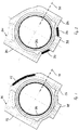
- the figures each show the large bearing eye of a connecting rod 100, 200, 300, 400, 500, 600 of an internal combustion engine not shown here.
- the connecting rods 100, 200, 300 each have a taring mass 108, 208, 308.
- the connecting rod 100, 200, 300, 400, 500, 600 is produced by the forging, sintering or sintering forging method and consists of a ferrous material with a carbon content of at least 0.3%, in particular from 0.3 to 0 , 8%, for example from C 70.
- the decisive factor is that areas to be coated or to be coated have the stated carbon content, so that, if appropriate, the connecting rod 100, 200, 300, 400, 500, 600 may also include areas having a different carbon content.
- the bearing eye is provided with a functional coating 106, 206, 306, 406 formed by coating at least its inner surface, wherein the coating comprises surface hardening by means of heat treatment.
- the compensation takes place, in particular in the context of a large-scale production cost at high, consistent quality by laser or induction hardening and subsequent tempering.
- the bearing eye is provided with a functional coating 506, 606 formed by coating its inner surface, the coating being applied laser-supported, for example by means of a laser-powder, laser-wire or laser-melt process.
- a functional coating 506, 606 formed by coating its inner surface, the coating being applied laser-supported, for example by means of a laser-powder, laser-wire or laser-melt process.
- the functional overlay 506, 606 is copper-based and comprises, in particular with connecting rods mounted on the crankshaft, for example a copper-zinc (CuZn), copper-tin (CuSn), copper-bismuth (CuBi) or copper-silver alloy (CuAg). , optionally with the addition of further alloying element as well as usual impurities.
- the functional overlay 506, 606 may also comprise a tin, eg Sn x Sb x Cu y , or aluminum-based alloy.
- the produced layer thickness is approx. 0.5 - 2 mm, which is reduced within a subsequent finishing to approx. 0.15 - 0.3 mm.
- the functional support 506, 606 is a hard material layer having a hardness of at least 55 HRC, the Composition 1.2% by weight of carbon (C), 4.5% by weight of chromium (Cr), 5.5% by weight of tungsten (W), 4% by weight of vanadium (V), balance iron ( Fe) or cobalt base alloy such as stellite.
- the generated layer thickness is approx. 1.5 - 3 mm, which is reduced to approx. 0.7 - 1.5 mm within the scope of a subsequent finish machining.
- a connecting rod bearing cap 104, 204, 304, 404, 504, 604 is separable from the big end 102, 202, 302, 402, 502, 602.
- the stresses introduced during tempering and / or coating are released.
- the individual components of the fracture-separated component, the connecting rod 102, 202, 302, 402, 502, 602 and the cover 104, 204, 304, 404, 502, 602, after the fracture separation does not "spring up" different degrees, are before the Fracture cutting targeted introduced counter-stresses to the introduced during the annealing and / or coating, stresses by the component is partially heat-treated in predetermined areas.
- the rigidities are achieved by means of counterhardening zones 112, 212, 214, 312, 314, 316, 412, 414, 514, 614, 618, 620 on connecting rod 102, 202, 302, 402, 502, 602 and / or connecting rod bearing cover 104 , 204, 304, 404, 504, 604.
- the required type, position and dimension of the counterhardening zones 112, 212, 214, 312, 314, 316, 412, 414, 514, 614, 618, 620 are calculated using a virtual model. According to another embodiment, the requirements imposed on the counterhardening zones 112, 212, 214, 312, 314, 316, 412, 414, 514, 614, 618, 620 are determined empirically by fracture separation of reference components without Counterhardening zones determined before the fracture separation for the targeted introduction of countervoltages.
- the amount of spring-back is determined and, accordingly, opposing stresses are introduced by forming processes such as cold calibration, needling, rolling (rolling), tumbling or hardening of the planar surfaces
- FIG. 1 shows a connecting rod 100 with counter-hardening zone 112 at the big end 102
- FIG. 2 a connecting rod 200 with counter-hardening zones 212, 214 on the connecting-rod bearing cover 204 on the side of the taring mass 208
- FIG. 3 a connecting rod 300 with counter-hardening zones 312, 314, 316 at the connecting rod end 302 and at the connecting rod bearing cover 304 at the side of the taring mass 308
- FIG. 4 shows a connecting rod 400 with counter-hardening zones 412, 414 at connecting-rod end 402 and centered continuously at the connecting-rod bearing cover 414
- FIG. 5 FIG.
- FIG. 2 shows a connecting rod 500 with a bearing surface 506 integrated by coating and a counterhardening zone 514 arranged in the immediate vicinity of the bearing coating 506 on the connecting rod bearing cover 504 and
- FIG. 6 10 shows a connecting rod 600 having a coating integrated bearing surface 606 and a counter-hardening zone 514 slightly spaced from the bearing coating 606 with two extended regions 618, 620 at the connecting rod bearing cap 504.
- the connecting rod bearing cover 104, 204 is broken by cracking , 304, 404, 504, 604 from the big end 102, 202, 302, 402502, 602 separated, wherein previously Pleuellager inside the break separation plane a weakening line is formed.
- the weakening line is formed by depressions arranged near the surface and by means of webs spaced apart from one another in a brittle material region to achieve a fracture force-dependent crack initiation in the webs. Since the entirety of the webs results in a shorter length than the length or width of the respective bearing arrangement or of the component, the fact that, due to the introduced fracture separation force in the weakened line shortened by the webs, first of all starter cracks are generated for the fracture initiation will result the further fraction separation are decisive.
- the brittle material region is produced as a brittle mixed phase in the case of a thermally cohesive connection between a base material of the component or the bearing arrangement and a functional overlay, the finding being based on the knowledge that the brittle mixed phase is produced by means of a high-energy beam.
- a high-energy beam such as As a laser, is produced during melting of the component base material and simultaneous melting of serving as a functional support filler material.
- blind hole-like depressions are formed by means of a high-energy beam in such a way that they enforce the brittle mixed phase or alternatively cut through.
- the method is preferably used for the arrangement of a sliding bearing layer as a functional support in a bearing arrangement of a connecting rod, wherein with the fracture separation designed as a connecting rod Bearing arrangement, the sliding bearing layer is also fracture-separated.
- the sliding bearing material forms the used brittle mixed phase with the iron material.
- a heat-dependent ductile martensite layer which counteracts a rapid crack propagation.
- blind hole-like depressions produced by means of a jet, in particular a laser beam, for forming the line of weakness extend the sliding bearing layer and the brittle mixed phase into the subsequent, heat-dependent, ductile martensite layer, wherein the energy input through the each jet is selected so that the portions of the depressions are limited in ductile martensite of a brittle mixed phase in connection with the embrittled martensite layer.
- embrittled martensite layers delimiting the sections of the blind hole-like depressions serve in connection with the webs formed in the brittle mixing phase to form starter cracks on the one hand and the propagation of such starter cracks on the other hand in the ductile martensite layer.
- the respective bearing alloy with a major amount of copper may be added to admixtures of iron or manganese or silicon, which additionally support the embrittlement.
- the above-described selection of plain bearing materials is such that by at least one alloying component, the formation of the brittle mixed phase is supported in all aforementioned bearing arrangements, which may optionally find additional support by a corresponding gas atmosphere during melting of the respective bearing material.
- the weakening lines in the connecting rod bearing and thus the separating plane are in a plane inclined relative to the axis of the connecting rod by the angle ⁇ , so that a largely shock-free or low-impact rolling over of the parting line is made possible.
- the angle ⁇ is at least 3 °.
- finishing can be carried out, including cleaning, surface grinding and / or honing.
- the invention is illustrated with reference to a connecting rod of an internal combustion engine, it can also be used in a bearing of a shaft, in particular a crankshaft, camshaft or intermediate shaft of an internal combustion engine.
Landscapes
- Engineering & Computer Science (AREA)
- Chemical & Material Sciences (AREA)
- Mechanical Engineering (AREA)
- Physics & Mathematics (AREA)
- Thermal Sciences (AREA)
- Crystallography & Structural Chemistry (AREA)
- Materials Engineering (AREA)
- Metallurgy (AREA)
- Organic Chemistry (AREA)
- General Engineering & Computer Science (AREA)
- Shafts, Cranks, Connecting Bars, And Related Bearings (AREA)
- Coating By Spraying Or Casting (AREA)
Claims (5)
- Procédé de fabrication d'un composant séparé par rupture (100, 200, 300, 400, 500, 600) en un acier au carbone comportant au moins par zones une amélioration de structure et/ou un revêtement, des tensions étant introduites,
caractérisé par
un traitement thermique partiel avant la séparation par rupture pour permettre l'introduction ciblée de tensions antagonistes ou de déformations pour permettre d'influer sur une détente de constituants individuels du composant après la séparation par rupture. - Composé conforme à la revendication 1,
caractérisé en ce que
le traitement thermique partiel est effectué dans des zones prédéfinies (112, 212, 214, 312, 314, 316, 412, 414, 514, 614, 618, 620). - Composé conforme à la revendication 2,
caractérisé en ce que
les zones prédéfinies (112, 212, 214, 312, 314, 316, 412, 414, 514, 614, 618, 620) sont déterminées par calcul à partir d'un modèle virtuel. - Procédé conforme à la revendication 2,
caractérisé en ce que
les zones prédéfinies (112, 212, 214, 312, 314, 316, 412, 414, 514, 614, 618, 620) sont déterminées de manière empirique par séparation par rupture de composants de référence sans traitement thermique partiel avant la séparation par rupture pour permettre l'introduction ciblée de tensions antagonistes. - Procédé conforme à la revendication 1,
caractérisé en ce que
le composant séparé par rupture (100, 200, 300, 400, 500, 600) est une bielle d'un moteur à combustion interne ou un palier d'un vilebrequin, d'un arbre à came ou d'un arbre intermédiaire d'un moteur à combustion interne.
Applications Claiming Priority (1)
| Application Number | Priority Date | Filing Date | Title |
|---|---|---|---|
| DE102007021622A DE102007021622A1 (de) | 2007-05-09 | 2007-05-09 | Verfahren zur Herstellung eines bruchgetrennten Bauteils, danach hergestelltes Bauteil sowie dessen Verwendung |
Publications (3)
| Publication Number | Publication Date |
|---|---|
| EP1990127A2 EP1990127A2 (fr) | 2008-11-12 |
| EP1990127A3 EP1990127A3 (fr) | 2011-01-05 |
| EP1990127B1 true EP1990127B1 (fr) | 2017-12-27 |
Family
ID=39577722
Family Applications (1)
| Application Number | Title | Priority Date | Filing Date |
|---|---|---|---|
| EP08006565.9A Not-in-force EP1990127B1 (fr) | 2007-05-09 | 2008-03-31 | Procédé de fabrication d'un composant séparable par fracture, composant ainsi fabriqué et son utilisation |
Country Status (3)
| Country | Link |
|---|---|
| EP (1) | EP1990127B1 (fr) |
| DE (1) | DE102007021622A1 (fr) |
| ES (1) | ES2659790T3 (fr) |
Families Citing this family (6)
| Publication number | Priority date | Publication date | Assignee | Title |
|---|---|---|---|---|
| DE102010010642B4 (de) | 2010-03-09 | 2024-05-29 | Bayerische Motoren Werke Aktiengesellschaft | Verfahren zur Herstellung eines bruchgetrennten Bauteils und nach dem Verfahren hergestelltes Bauteil |
| DE102011101857A1 (de) * | 2011-05-18 | 2012-11-22 | Man Truck & Bus Ag | Verfahren zur Herstellung metallischer Bauteile |
| CN105945528B (zh) * | 2016-06-20 | 2018-05-08 | 安徽省瑞杰锻造有限责任公司 | 一种电液锤上下v型砧的加工工艺 |
| US11117191B2 (en) * | 2018-10-30 | 2021-09-14 | GM Global Technology Operations LLC | Methods for manufacturing connecting rod assemblies and crankshaft assemblies |
| CN110587241B (zh) * | 2019-10-10 | 2021-08-13 | 吉林大学 | 发动机连杆的制造方法 |
| DE102019131591A1 (de) * | 2019-11-22 | 2021-05-27 | Renk Aktiengesellschaft | Herstellungsverfahren einer Gleitschicht eines Gleitlagers unter Verwendung einer Legierung und/oder eines Materials |
Family Cites Families (5)
| Publication number | Priority date | Publication date | Assignee | Title |
|---|---|---|---|---|
| DE4303592A1 (de) * | 1993-02-08 | 1994-08-11 | Krebsoege Gmbh Sintermetall | Verfahren zum Herstellen eines Bauteils mit wenigstens einem geteilten Lagersitz |
| DE19911067A1 (de) * | 1999-03-12 | 2000-09-14 | Bayerische Motoren Werke Ag | Verfahren zur Ausbildung einer Anrißstelle zum Bruchtrennen eines Bauteiles aus einem Kohlenstoffstahl |
| DE10022884B4 (de) * | 2000-05-10 | 2007-08-16 | Man Nutzfahrzeuge Ag | Verfahren zur Bruchtrennung in Bauteilen oder deren Vormaterial |
| DE102004018921A1 (de) | 2004-04-20 | 2005-11-17 | Bayerische Motoren Werke Ag | Verfahren zur Herstellung einer Pleuelstange sowie eines Kolbenbolzens |
| US7416621B2 (en) * | 2005-07-22 | 2008-08-26 | Gkn Sinter Metals, Inc. | Laser rounding and flattening of cylindrical parts |
-
2007
- 2007-05-09 DE DE102007021622A patent/DE102007021622A1/de not_active Withdrawn
-
2008
- 2008-03-31 ES ES08006565.9T patent/ES2659790T3/es active Active
- 2008-03-31 EP EP08006565.9A patent/EP1990127B1/fr not_active Not-in-force
Non-Patent Citations (1)
| Title |
|---|
| None * |
Also Published As
| Publication number | Publication date |
|---|---|
| DE102007021622A1 (de) | 2008-11-13 |
| EP1990127A3 (fr) | 2011-01-05 |
| EP1990127A2 (fr) | 2008-11-12 |
| ES2659790T3 (es) | 2018-03-19 |
Similar Documents
| Publication | Publication Date | Title |
|---|---|---|
| DE102007023087B4 (de) | Verfahren zur Herstellung eines Nockens | |
| EP2547800B1 (fr) | Procédé de fabrication de pièces en acier léger de construction ayant des propriétés de matériau ajustables suivant l'épaisseur de paroi | |
| EP3083239A1 (fr) | Produit plat en acier, composant en acier réalisé à partir d'un tel produit plat en acier et carrosserie pour véhicule automobile | |
| DE102004018921A1 (de) | Verfahren zur Herstellung einer Pleuelstange sowie eines Kolbenbolzens | |
| EP1263540B1 (fr) | Procede pour produire des pieces en acier a faible epaisseur de paroi, et pieces ainsi produites | |
| EP1990127A2 (fr) | Procédé de fabrication d'un composant séparable par fracture, composant ainsi fabriqué et son utilisation | |
| EP2545292B1 (fr) | Procédé de fabrication d'une pièce en deux parties | |
| DE102009035702A1 (de) | Fahrwerksbauteil für ein Kraftfahrzeug und Verfahren zur Herstellung | |
| EP3577240B1 (fr) | Procédé de fabrication d'une roue de véhicule en tôle d'acier | |
| EP3323902A1 (fr) | Matériau en acier contenant des particules dures, produit de la métallurgie des poudres, procédé de production d'un composant à partir d'un tel matériau d'acier et composant ainsi fabriqué | |
| WO2018029191A1 (fr) | Élément de châssis présentant une résistance élevée en service | |
| EP2414552B1 (fr) | Pivots à rotule en aciers à structure bainitique pour de véhicules à usage personnel et de véhicules utilitaires légers | |
| DE69427238T2 (de) | Lager | |
| EP3625045B1 (fr) | Matériau de formage à chaud, pièce et utilisation correspondante | |
| DE102016211411A1 (de) | Fahrzeugrad und Verwendung | |
| DE102012003791B3 (de) | Verfahren zur Herstellung hochfester Formteile aus Stahlguss mit TRIP-Effekt und mit austenitisch-martensitischem Gefüge | |
| EP3356077B1 (fr) | Utilisation d'une pièce en acier possédant une qualité de surface améliorée | |
| EP2285998B1 (fr) | Procédé de fabrication d'un piston pour un moteur à combustion interne et piston pour un moteur à combustion interne | |
| EP3211109A1 (fr) | Procédé de fabrication d'un moule de formage à chaud et moule formage à chaud ainsi obtenu | |
| DE102014101318A1 (de) | Verfahren zum Herstellen eines Kraftfahrzeugachsbauteils | |
| DE69909940T2 (de) | Teile aus martensitischem rostfreiem Stahl und Verfahren zu ihrer Herstellung | |
| DE102009049398C5 (de) | Verfahren zur Herstellung eines Strukturbauteils für ein Kraftfahrzeug und Strukturbauteil | |
| DE102013213752B4 (de) | Verfahren zur Herstellung eines Werkzeugs für die Bearbeitung von Blechen sowie Werkzeug | |
| DE102017115803A1 (de) | Verfahren zur Herstellung eines Metallbauteils | |
| DE10014656A1 (de) | Kalt/Warmbearbeitungs- und Wärmebehandlungsverfahren für hochlegierten Stahl der Gruppe mit hohem Kohlenstoffgehalt |
Legal Events
| Date | Code | Title | Description |
|---|---|---|---|
| PUAI | Public reference made under article 153(3) epc to a published international application that has entered the european phase |
Free format text: ORIGINAL CODE: 0009012 |
|
| AK | Designated contracting states |
Kind code of ref document: A2 Designated state(s): AT BE BG CH CY CZ DE DK EE ES FI FR GB GR HR HU IE IS IT LI LT LU LV MC MT NL NO PL PT RO SE SI SK TR |
|
| AX | Request for extension of the european patent |
Extension state: AL BA MK RS |
|
| PUAL | Search report despatched |
Free format text: ORIGINAL CODE: 0009013 |
|
| AK | Designated contracting states |
Kind code of ref document: A3 Designated state(s): AT BE BG CH CY CZ DE DK EE ES FI FR GB GR HR HU IE IS IT LI LT LU LV MC MT NL NO PL PT RO SE SI SK TR |
|
| AX | Request for extension of the european patent |
Extension state: AL BA MK RS |
|
| 17P | Request for examination filed |
Effective date: 20110120 |
|
| AKX | Designation fees paid |
Designated state(s): DE ES FR GB IT |
|
| RAP1 | Party data changed (applicant data changed or rights of an application transferred) |
Owner name: BAYERISCHE MOTOREN WERKE AKTIENGESELLSCHAFT |
|
| 17Q | First examination report despatched |
Effective date: 20170526 |
|
| REG | Reference to a national code |
Ref country code: DE Ref legal event code: R079 Ref document number: 502008015817 Country of ref document: DE Free format text: PREVIOUS MAIN CLASS: B23P0015000000 Ipc: C21D0001700000 |
|
| GRAP | Despatch of communication of intention to grant a patent |
Free format text: ORIGINAL CODE: EPIDOSNIGR1 |
|
| RIC1 | Information provided on ipc code assigned before grant |
Ipc: C21D 9/40 20060101ALI20170818BHEP Ipc: B23P 9/00 20060101ALI20170818BHEP Ipc: F16C 33/14 20060101ALI20170818BHEP Ipc: F16C 9/04 20060101ALI20170818BHEP Ipc: B23P 15/00 20060101ALI20170818BHEP Ipc: C21D 9/00 20060101ALI20170818BHEP Ipc: C21D 1/70 20060101AFI20170818BHEP |
|
| INTG | Intention to grant announced |
Effective date: 20170907 |
|
| GRAS | Grant fee paid |
Free format text: ORIGINAL CODE: EPIDOSNIGR3 |
|
| GRAA | (expected) grant |
Free format text: ORIGINAL CODE: 0009210 |
|
| AK | Designated contracting states |
Kind code of ref document: B1 Designated state(s): DE ES FR GB IT |
|
| REG | Reference to a national code |
Ref country code: GB Ref legal event code: FG4D Free format text: NOT ENGLISH |
|
| REG | Reference to a national code |
Ref country code: DE Ref legal event code: R096 Ref document number: 502008015817 Country of ref document: DE |
|
| REG | Reference to a national code |
Ref country code: ES Ref legal event code: FG2A Ref document number: 2659790 Country of ref document: ES Kind code of ref document: T3 Effective date: 20180319 |
|
| PGFP | Annual fee paid to national office [announced via postgrant information from national office to epo] |
Ref country code: DE Payment date: 20180322 Year of fee payment: 11 |
|
| REG | Reference to a national code |
Ref country code: DE Ref legal event code: R097 Ref document number: 502008015817 Country of ref document: DE |
|
| PLBE | No opposition filed within time limit |
Free format text: ORIGINAL CODE: 0009261 |
|
| STAA | Information on the status of an ep patent application or granted ep patent |
Free format text: STATUS: NO OPPOSITION FILED WITHIN TIME LIMIT |
|
| GBPC | Gb: european patent ceased through non-payment of renewal fee |
Effective date: 20180331 |
|
| 26N | No opposition filed |
Effective date: 20180928 |
|
| PG25 | Lapsed in a contracting state [announced via postgrant information from national office to epo] |
Ref country code: GB Free format text: LAPSE BECAUSE OF NON-PAYMENT OF DUE FEES Effective date: 20180331 Ref country code: IT Free format text: LAPSE BECAUSE OF NON-PAYMENT OF DUE FEES Effective date: 20180331 |
|
| PG25 | Lapsed in a contracting state [announced via postgrant information from national office to epo] |
Ref country code: FR Free format text: LAPSE BECAUSE OF NON-PAYMENT OF DUE FEES Effective date: 20180331 |
|
| REG | Reference to a national code |
Ref country code: ES Ref legal event code: FD2A Effective date: 20190826 |
|
| REG | Reference to a national code |
Ref country code: DE Ref legal event code: R119 Ref document number: 502008015817 Country of ref document: DE |
|
| PG25 | Lapsed in a contracting state [announced via postgrant information from national office to epo] |
Ref country code: ES Free format text: LAPSE BECAUSE OF NON-PAYMENT OF DUE FEES Effective date: 20180401 |
|
| PG25 | Lapsed in a contracting state [announced via postgrant information from national office to epo] |
Ref country code: DE Free format text: LAPSE BECAUSE OF NON-PAYMENT OF DUE FEES Effective date: 20191001 |