EP1990130A1 - Machine de traitement de bords - Google Patents
Machine de traitement de bords Download PDFInfo
- Publication number
- EP1990130A1 EP1990130A1 EP08003237A EP08003237A EP1990130A1 EP 1990130 A1 EP1990130 A1 EP 1990130A1 EP 08003237 A EP08003237 A EP 08003237A EP 08003237 A EP08003237 A EP 08003237A EP 1990130 A1 EP1990130 A1 EP 1990130A1
- Authority
- EP
- European Patent Office
- Prior art keywords
- processing machine
- edge processing
- hood part
- movable hood
- machine according
- Prior art date
- Legal status (The legal status is an assumption and is not a legal conclusion. Google has not performed a legal analysis and makes no representation as to the accuracy of the status listed.)
- Withdrawn
Links
- 238000005096 rolling process Methods 0.000 claims description 3
- 238000003754 machining Methods 0.000 claims 1
- 230000000717 retained effect Effects 0.000 abstract 1
- 239000000853 adhesive Substances 0.000 description 3
- 230000001070 adhesive effect Effects 0.000 description 3
- 238000009434 installation Methods 0.000 description 2
- 239000011358 absorbing material Substances 0.000 description 1
- 238000006073 displacement reaction Methods 0.000 description 1
- 239000006228 supernatant Substances 0.000 description 1
- 230000001960 triggered effect Effects 0.000 description 1
- 238000009966 trimming Methods 0.000 description 1
Images


Classifications
-
- B—PERFORMING OPERATIONS; TRANSPORTING
- B23—MACHINE TOOLS; METAL-WORKING NOT OTHERWISE PROVIDED FOR
- B23Q—DETAILS, COMPONENTS, OR ACCESSORIES FOR MACHINE TOOLS, e.g. ARRANGEMENTS FOR COPYING OR CONTROLLING; MACHINE TOOLS IN GENERAL CHARACTERISED BY THE CONSTRUCTION OF PARTICULAR DETAILS OR COMPONENTS; COMBINATIONS OR ASSOCIATIONS OF METAL-WORKING MACHINES, NOT DIRECTED TO A PARTICULAR RESULT
- B23Q11/00—Accessories fitted to machine tools for keeping tools or parts of the machine in good working condition or for cooling work; Safety devices specially combined with or arranged in, or specially adapted for use in connection with, machine tools
- B23Q11/08—Protective coverings for parts of machine tools; Splash guards
- B23Q11/0891—Protective coverings for parts of machine tools; Splash guards arranged between the working area and the operator
-
- B—PERFORMING OPERATIONS; TRANSPORTING
- B24—GRINDING; POLISHING
- B24B—MACHINES, DEVICES, OR PROCESSES FOR GRINDING OR POLISHING; DRESSING OR CONDITIONING OF ABRADING SURFACES; FEEDING OF GRINDING, POLISHING, OR LAPPING AGENTS
- B24B9/00—Machines or devices designed for grinding edges or bevels on work or for removing burrs; Accessories therefor
-
- F—MECHANICAL ENGINEERING; LIGHTING; HEATING; WEAPONS; BLASTING
- F16—ENGINEERING ELEMENTS AND UNITS; GENERAL MEASURES FOR PRODUCING AND MAINTAINING EFFECTIVE FUNCTIONING OF MACHINES OR INSTALLATIONS; THERMAL INSULATION IN GENERAL
- F16P—SAFETY DEVICES IN GENERAL; SAFETY DEVICES FOR PRESSES
- F16P3/00—Safety devices acting in conjunction with the control or operation of a machine; Control arrangements requiring the simultaneous use of two or more parts of the body
- F16P3/001—Safety devices for guarding the human operator of punch presses or like machine tools performing an opening and closing travel
-
- B—PERFORMING OPERATIONS; TRANSPORTING
- B23—MACHINE TOOLS; METAL-WORKING NOT OTHERWISE PROVIDED FOR
- B23Q—DETAILS, COMPONENTS, OR ACCESSORIES FOR MACHINE TOOLS, e.g. ARRANGEMENTS FOR COPYING OR CONTROLLING; MACHINE TOOLS IN GENERAL CHARACTERISED BY THE CONSTRUCTION OF PARTICULAR DETAILS OR COMPONENTS; COMBINATIONS OR ASSOCIATIONS OF METAL-WORKING MACHINES, NOT DIRECTED TO A PARTICULAR RESULT
- B23Q2210/00—Machine tools incorporating a specific component
- B23Q2210/006—Curved guiding rails
-
- E—FIXED CONSTRUCTIONS
- E05—LOCKS; KEYS; WINDOW OR DOOR FITTINGS; SAFES
- E05Y—INDEXING SCHEME ASSOCIATED WITH SUBCLASSES E05D AND E05F, RELATING TO CONSTRUCTION ELEMENTS, ELECTRIC CONTROL, POWER SUPPLY, POWER SIGNAL OR TRANSMISSION, USER INTERFACES, MOUNTING OR COUPLING, DETAILS, ACCESSORIES, AUXILIARY OPERATIONS NOT OTHERWISE PROVIDED FOR, APPLICATION THEREOF
- E05Y2201/00—Constructional elements; Accessories therefor
- E05Y2201/60—Suspension or transmission members; Accessories therefor
- E05Y2201/622—Suspension or transmission members elements
- E05Y2201/684—Rails; Tracks
-
- E—FIXED CONSTRUCTIONS
- E05—LOCKS; KEYS; WINDOW OR DOOR FITTINGS; SAFES
- E05Y—INDEXING SCHEME ASSOCIATED WITH SUBCLASSES E05D AND E05F, RELATING TO CONSTRUCTION ELEMENTS, ELECTRIC CONTROL, POWER SUPPLY, POWER SIGNAL OR TRANSMISSION, USER INTERFACES, MOUNTING OR COUPLING, DETAILS, ACCESSORIES, AUXILIARY OPERATIONS NOT OTHERWISE PROVIDED FOR, APPLICATION THEREOF
- E05Y2800/00—Details, accessories and auxiliary operations not otherwise provided for
- E05Y2800/10—Additional functions
- E05Y2800/122—Telescopic action
-
- E—FIXED CONSTRUCTIONS
- E05—LOCKS; KEYS; WINDOW OR DOOR FITTINGS; SAFES
- E05Y—INDEXING SCHEME ASSOCIATED WITH SUBCLASSES E05D AND E05F, RELATING TO CONSTRUCTION ELEMENTS, ELECTRIC CONTROL, POWER SUPPLY, POWER SIGNAL OR TRANSMISSION, USER INTERFACES, MOUNTING OR COUPLING, DETAILS, ACCESSORIES, AUXILIARY OPERATIONS NOT OTHERWISE PROVIDED FOR, APPLICATION THEREOF
- E05Y2999/00—Subject-matter not otherwise provided for in this subclass
Definitions
- the invention relates to an edge processing machine with a machine frame for arranging at least one processing unit for processing the edges of a plate-shaped workpiece, and having at least one hood for covering at least one processing unit, wherein the hood has a movable hood part, which between a closed position and an open position and is movable.
- Such edge processing machines are used in particular in the form of edge banding machines, with the help of which an edge band can be glued to the edges of a plate-shaped workpiece.
- Exceeding Umleimermaterial can usually be separated and in addition, the corners and edges can be edited, in particular milled and / or polished.
- the plate-shaped workpieces are continuously moved during their processing by means of a conveyor of the edge processing machine along a feed direction, so that the entire processing of the workpiece during its transport takes place.
- the processing units used are usually covered for safety reasons by hoods.
- the hoods on a movable hood part which is movable between a closed position and an open position back and forth. In the open position, the user is allowed access to the processing unit, and in the closed position, the processing unit is covered.
- the movable hood part is usually mounted so as to be pivotable about a pivot axis oriented parallel to the longitudinal direction of the edge processing machine and, starting from its closed position, can be pivoted upward by the user in the direction away from the machine frame.
- the pivotable mounting of the movable hood part has proven itself insofar as this provides the user with a sufficiently large access opening.
- the movable hood part can be locked in its open position and therefore does not affect the user of the edge processing machine. For opening and closing the hood, however, a considerable amount of space is required, since otherwise the movable hood part can not be pivoted unhindered.
- the lower edge of the movable hood part when this assumes its open position, at a considerable distance from the footprint of the edge processing machine and therefore can be achieved by the user when using relatively large hood sometimes only with difficulty.
- the problem is often the not inconsiderable weight of the movable hood part, through which the movement of the hood part is made more difficult.
- Object of the present invention is to develop an edge processing machine of the type mentioned in such a way that reduces the space required to open and close the hood space and the opening and closing of the hood can be simplified.
- the sliding holder has the advantage that the movable hood part can be moved in a simple manner between its closed position and its open position back and forth.
- the space required for opening and closing the hood space is reduced and even with large-size hoods, the movable hood part can be taken in its open position by the user in a simple manner.
- the movable hood part is, starting from its closed position in the direction away from the machine frame upwards displaced. In its open position, the movable hood part projects upwards.
- the space required to open and close the hood space before the edge processing machine can be kept very low.
- the sliding movement is at least supported by a drive.
- the movable hood part can therefore be automatically displaced by means of the drive, for example, after entering a control command by the user. But at least the movable hood part is acted upon by the drive with a pushing force that supports the manual shifting. The user thus does not have to overcome its full weight to move the movable hood part, but at least part of the weight is taken over by the drive to move the hood part.
- the Drive can be configured for example as an electric motor or in the form of a pneumatic or hydraulic piston-cylinder unit.
- the storage of the movable hood part is preferably carried out on a fixed hood part. It can be provided, for example, that the movable hood part forms an end wall of the hood, which is held displaceably on stationary side walls of the hood.
- the stroke of the movable hood part ie the path of the movable hood part, which this travels between its closed position and its open position, amounts to at least two-thirds of its vertical extent.
- the user is provided a relatively large access opening in the open position of the movable hood part.
- the stroke of the movable hood part is at least four-fifths of its vertical extent.
- guide rails are used for storage of the movable hood part. These are held in an advantageous embodiment of a fixed hood part.
- the guide rails are designed as telescopic rails. These have a fixed rail and at least one movable rail.
- the fixed rail can, for example be fixed to the fixed hood part and the movable rail can be fixed to the movable hood part.
- the telescopic rails are configured at least in three parts, comprising a fixed rail and at least two movable rails.
- the more than two-part design of the telescopic rails makes it possible to considerably expand the stroke of the movable hood part.
- the movable hood part is held displaceably in guide profiles. This allows a particularly stable mounting of the movable hood part.
- the guide profiles each receive an edge region of the movable hood part in itself. They can be configured in particular U-shaped.
- the guide profiles are arcuately curved.
- the installation space required above the edge machine for opening the hood can be reduced by using guide profiles with an arc-shaped course pointing backwards.
- the movable hood part can thereby be transferred into an obliquely oriented to the vertical open position.
- the guide profiles project with their upper end regions over the hood.
- the movable hood part can be reliably held in its open position with a lower edge portion in the guide profiles, without thereby the stroke of the movable hood part must be reduced.
- this is held displaceable in an advantageous embodiment by means of rolling elements in the guide rails or guide profiles.
- rolling elements By means of the rolling elements, the friction between the guide rails or guide profiles and the movable hood part can be reduced.
- the edge processing machine comprises a plurality of hoods arranged next to one another, whose mutually immediately adjacent movable hood parts are held displaceably on common guide elements.
- the number of guide elements can be reduced.
- guide elements for example, the guide profiles already explained above can be used.
- a cross-sectionally H-shaped guide profile may be arranged, in each of which an edge region of a movable hood part can dip on both sides.
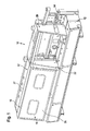
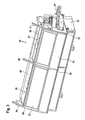
- FIGS. 1 and 2 shows a first embodiment of an overall occupied by the reference numeral 10 edge processing machine. It comprises a machine frame 12, on which a conveyor 14 is held for transporting plate-shaped workpieces. During the transport of the workpieces whose edges can be edited by means of known per se and therefore not shown to achieve a better overview in the drawing processing units. In particular, a lipping can be glued to the edges of the workpiece.
- the in the FIGS. 1 and 2 Edge processing machine 10 shown has a hood 16 with a fixed hood part 17 and with a movable hood part 18.
- the hood 16 extends approximately over half the length of the edge processing machine 10. Laterally adjacent to the hood 16, a frame 20 is held on the machine part 12.
- the hood 16 covers not shown in the drawing, processing units of the edge processing machine 10 and other processing units can be positioned in the frame 20.
- the frame 20 may receive an adhesive applicator for applying an adhesive to the edges of the workpiece and a printing unit for pressing a frill against the edge after the adhesive has been applied thereto.
- the hood 16 may cover electric motor driven trimming units with which supernatants of the glued edge band can be separated.
- the hood 16 forms a soundproofing and can be covered on the inside with sound-absorbing material.
- the fixed hood part 17 comprises a first side wall 21 and a second side wall 22, which are fixed to the machine frame 12. Between them they define an access opening 24 which can be closed by the movable hood part 18.
- the latter comprises an end wall 26 and a ceiling wall 27, which protrudes from the upper edge region of the end wall 26 to the rear.
- the movable hood part 18 is held by means of two guide rails 29 and 30 slidably on the fixed hood part 17.
- the guide rail 29 is arranged on the front side of the first side wall 21 and the guide rail 30 is disposed on the front side of the second side wall 22.
- the movable hood part 18 can be placed between the in FIG. 1 illustrated closed position and in FIG. 2 shown open position manually shifted back and forth.
- the stroke of the movable hood part 18 is in this case about 80% of its vertical extent.
- the guide rails 29 and 30 are arranged slightly inclined to the vertical, so that the movable hood part 18 can be moved starting from its closed position obliquely upwards.
- the movable hood part 18 can be manually displaced by the user in a substantially vertical direction, wherein the sliding movement is supported by a pneumatic drive.
- a pneumatic drive Alternatively, an electric or hydraulic drive could be used. Such drives are known per se and therefore in the FIGS. 1 and 2 not shown.
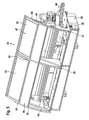
- FIGS. 3 to 6 a second embodiment of an edge processing machine according to the invention is shown, which is generally designated by the reference numeral 40. It comprises a machine frame 42 on which a conveyor 44 is fixed for transporting plate-shaped workpieces.
- the edges of the workpieces can in a corresponding manner, as described above with reference to the in the FIGS. 1 and 2 illustrated edge processing machine 10 has already been explained, are processed.
- the processing units required for this purpose are to achieve a better overview in the FIGS. 3 to 6 not shown.
- the edge processing machine 40 has a first hood 46 and a second hood 47, which in the closed state, the processing units cover the edge processing machine 40.
- the two hoods 46, 47 each have a fixed hood part 49 or 50 and a movable hood part 52 and 53, respectively.
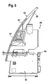
- the moving hood parts are between the in FIG. 3 illustrated closed position and in FIG. 5 shown open position back and forth.
- For displaceable mounting guide profiles 55, 56 and 57 are used.
- the middle guide profile 56 which is arranged between the two movable hood parts 52 and 53, has an H-shaped cross section and receives on both sides in each case an edge region of the movable hood parts 52 and 53.
- the outer guide profiles 55 and 57 each have a U-shaped cross section and each receive an outer edge portion of a movable hood part 52 and 53, respectively.
- the guide profiles 55, 56 and 57 are curved in each case arcuately. This is especially true FIG. 6 clear. With an upper end portion 59, 60 and 61, the guide profiles 55, 56 and 57 protrude beyond the upper end of the fixed hood parts 49 and 50. In its closed position, the movable hood parts 52 and 53 with their mutually facing and their opposite edges completely in the guide profiles 55, 56 and 57 held.
- the movable hood parts 52 and 53 protrude beyond the guide profiles 55, 56 and 57, but the upper end sections 59, 60 and 61 also assume an edge section of the movable hood parts 52, 53 even in the open position of the movable hood parts 52, 53 ,
- the movable hood parts 52, 53 held even in its open position still stable in the guide sections 55, 56, 57.
- the sliding movements of the movable hood parts 52, 53 of the edge processing machine 40 can be supported by electric motor, pneumatically or hydraulically at least.
- a pneumatic drive is used with piston-cylinder units, each of which moves a push rod 64 hinged to an upper end region of a movable hood part 52 or 53 in the vertical direction.
- the movable hood parts 52, 53 are automatically displaced.
- a control element for. B. press a button.
- a corresponding control command can also be triggered by a control program.
- the two movable hood parts 52 and 53 can be moved independently between their open position and its closed position. In their closed position, they are slightly inclined to the vertical, whereas they assume in their open position due to the arcuate course of the guide profiles 55, 56 and 57 inclined to the vertical at an angle of approximately 45 ° inclined position. As a result, the installation space required above the edge processing machine 40 for opening and closing the hoods 46 and 47 is reduced.
Landscapes
- Engineering & Computer Science (AREA)
- Mechanical Engineering (AREA)
- General Engineering & Computer Science (AREA)
- Auxiliary Devices For Machine Tools (AREA)
- Treatment Of Fiber Materials (AREA)
Applications Claiming Priority (1)
| Application Number | Priority Date | Filing Date | Title |
|---|---|---|---|
| DE102007023171A DE102007023171A1 (de) | 2007-05-10 | 2007-05-10 | Kantenbearbeitungsmaschine |
Publications (1)
| Publication Number | Publication Date |
|---|---|
| EP1990130A1 true EP1990130A1 (fr) | 2008-11-12 |
Family
ID=39724461
Family Applications (1)
| Application Number | Title | Priority Date | Filing Date |
|---|---|---|---|
| EP08003237A Withdrawn EP1990130A1 (fr) | 2007-05-10 | 2008-02-22 | Machine de traitement de bords |
Country Status (2)
| Country | Link |
|---|---|
| EP (1) | EP1990130A1 (fr) |
| DE (2) | DE202007018984U1 (fr) |
Cited By (6)
| Publication number | Priority date | Publication date | Assignee | Title |
|---|---|---|---|---|
| WO2012055522A1 (fr) * | 2010-10-25 | 2012-05-03 | Rehau Ag + Co | Dispositif à paroi de levage |
| CN102729095A (zh) * | 2011-03-31 | 2012-10-17 | 维嘉数控科技(苏州)有限公司 | 一种大型机罩门自动升降装置 |
| FR2984186A1 (fr) * | 2011-12-16 | 2013-06-21 | Scl Internat Special Coating Lab | Machine de traitement de verres de lunettes semi-automatique |
| CN104875073A (zh) * | 2015-05-27 | 2015-09-02 | 佛山市普拉迪数控科技有限公司 | 一种转动式防护罩 |
| DE102022107819A1 (de) | 2022-04-01 | 2023-10-05 | Homag Gmbh | Vorrichtung zum Bearbeiten eines Werkstücks |
| EP4570425A1 (fr) * | 2023-12-14 | 2025-06-18 | DGSHAPE Corporation | Machine de coupe avec porte coulissante |
Families Citing this family (2)
| Publication number | Priority date | Publication date | Assignee | Title |
|---|---|---|---|---|
| CN105598771B (zh) * | 2016-01-11 | 2017-12-26 | 新昌县丰瑞机械有限公司 | 探伤预处理一体机 |
| CN110587325B (zh) * | 2019-10-23 | 2021-07-20 | 长春光华学院 | 一种调节式数控机床导轨防护罩 |
Citations (4)
| Publication number | Priority date | Publication date | Assignee | Title |
|---|---|---|---|---|
| US3871437A (en) * | 1972-08-12 | 1975-03-18 | Ahm Mach Ltd | Machine guards |
| DE3316694C1 (de) * | 1983-05-06 | 1984-12-20 | Reich Spezialmaschinen GmbH, 7440 Nürtingen | Kantenschleifmaschine |
| US4498567A (en) * | 1982-09-30 | 1985-02-12 | R. A. Jones & Co., Inc. | Perimeter guard for a machine |
| DE202006004730U1 (de) * | 2006-03-24 | 2006-06-01 | Ape Engineering Gmbh | Einrichtung zum Ver- oder Bearbeiten von Gegenständen |
Family Cites Families (2)
| Publication number | Priority date | Publication date | Assignee | Title |
|---|---|---|---|---|
| DE19616483C2 (de) * | 1996-04-25 | 1998-05-07 | Chiron Werke Gmbh | Werkzeugmaschine mit einer Schiebetür |
| DE20121017U1 (de) * | 2001-12-28 | 2002-04-25 | REHAU AG + Co., 95111 Rehau | Vorrichtung zum Bearbeiten von Kantenstreifen |
-
2007
- 2007-05-10 DE DE202007018984U patent/DE202007018984U1/de not_active Expired - Lifetime
- 2007-05-10 DE DE102007023171A patent/DE102007023171A1/de not_active Ceased
-
2008
- 2008-02-22 EP EP08003237A patent/EP1990130A1/fr not_active Withdrawn
Patent Citations (4)
| Publication number | Priority date | Publication date | Assignee | Title |
|---|---|---|---|---|
| US3871437A (en) * | 1972-08-12 | 1975-03-18 | Ahm Mach Ltd | Machine guards |
| US4498567A (en) * | 1982-09-30 | 1985-02-12 | R. A. Jones & Co., Inc. | Perimeter guard for a machine |
| DE3316694C1 (de) * | 1983-05-06 | 1984-12-20 | Reich Spezialmaschinen GmbH, 7440 Nürtingen | Kantenschleifmaschine |
| DE202006004730U1 (de) * | 2006-03-24 | 2006-06-01 | Ape Engineering Gmbh | Einrichtung zum Ver- oder Bearbeiten von Gegenständen |
Cited By (8)
| Publication number | Priority date | Publication date | Assignee | Title |
|---|---|---|---|---|
| WO2012055522A1 (fr) * | 2010-10-25 | 2012-05-03 | Rehau Ag + Co | Dispositif à paroi de levage |
| CN102729095A (zh) * | 2011-03-31 | 2012-10-17 | 维嘉数控科技(苏州)有限公司 | 一种大型机罩门自动升降装置 |
| CN102729095B (zh) * | 2011-03-31 | 2015-10-28 | 维嘉数控科技(苏州)有限公司 | 一种大型机罩门自动升降装置 |
| FR2984186A1 (fr) * | 2011-12-16 | 2013-06-21 | Scl Internat Special Coating Lab | Machine de traitement de verres de lunettes semi-automatique |
| CN104875073A (zh) * | 2015-05-27 | 2015-09-02 | 佛山市普拉迪数控科技有限公司 | 一种转动式防护罩 |
| CN104875073B (zh) * | 2015-05-27 | 2017-10-13 | 佛山市普拉迪数控科技有限公司 | 一种转动式防护罩 |
| DE102022107819A1 (de) | 2022-04-01 | 2023-10-05 | Homag Gmbh | Vorrichtung zum Bearbeiten eines Werkstücks |
| EP4570425A1 (fr) * | 2023-12-14 | 2025-06-18 | DGSHAPE Corporation | Machine de coupe avec porte coulissante |
Also Published As
| Publication number | Publication date |
|---|---|
| DE202007018984U1 (de) | 2010-03-25 |
| DE102007023171A1 (de) | 2008-11-13 |
Similar Documents
| Publication | Publication Date | Title |
|---|---|---|
| DE2905841C2 (de) | Verfahren und Anlage zur Herstellung einer Verbundplatte | |
| EP1375219B1 (fr) | Store à enrouleur pour lunette arrière avec boîtier levant | |
| EP2539528B1 (fr) | Porte relevante munie d'un guidage mobile de vantail | |
| DE202007018984U1 (de) | Kantenbearbeitungsmaschine | |
| DE102011106942A1 (de) | Biegevorrichtung für stabförmige Werkstücke | |
| EP3678940B1 (fr) | Station de travail à mécanisme de course pour une machine d'emballage | |
| DE102018000344B3 (de) | Biegemaschine, Biegeeinheit, elektronische Steuereinrichtung und Verfahren zum Biegen eines Werkstücks aus Flachmaterial | |
| AT518076B1 (de) | Schubladenseitenwand | |
| DE102007022057A1 (de) | Plattenbearbeitungsanlage für großformatige Platten oder Plattenstapel, insbesondere Plattenaufteilsäge | |
| DE102019213486A1 (de) | Gargerät mit spezifischer Türöffnungsvorrichtung zum automatischen Schwenken einer versenkbaren Tür des Gargeräts, sowie Verfahren | |
| EP1254799B1 (fr) | Toit ouvrant pour véhicule | |
| DE4027717A1 (de) | Pressvorrichtung fuer abfaelle, insbesondere fuer muell | |
| DE202020002598U1 (de) | Biegemaschine zum Biegen eines Werkstücks aus Flachmaterial und Steuereinheit für eine solche Biegemaschine | |
| EP2062683A1 (fr) | Machine-outil dotée d'un espace de travail | |
| EP2875879B1 (fr) | Dispositif mécanique de transfert de pièce et dispositif de déchargement mécanique et agencement mécanique destiné au traitement de pièces à l'aide d'un tel dispositif de transfert de pièce | |
| EP0313099B1 (fr) | Toit ouvrant pour véhicules automobiles | |
| EP3067497A1 (fr) | Ferrure de porte coulissante pour un meuble | |
| DE2912665A1 (de) | Fahrzeugdach | |
| EP1058650B1 (fr) | Caisse, en particulier pour une machine d'emballage | |
| EP1809503B1 (fr) | Systeme de toit coulissant pour vehicules automobiles | |
| DE102021131573A1 (de) | Fahrzeugdachsystem mit einer Dachöffnung | |
| DE102005063454B4 (de) | Vorrichtung zum Trennen eines plastischen Tonstranges, mit einer allseitig wirksamen Kerbvorrichtung | |
| EP2848358B1 (fr) | Palette de transport de pièces à usiner | |
| DE102010050149A1 (de) | Vorrichtung zum Bearbeiten eines großformatigen Werkstücks | |
| DE10205068A1 (de) | Sonnenschutzbaugruppe für ein Fahrzeugdach |
Legal Events
| Date | Code | Title | Description |
|---|---|---|---|
| PUAI | Public reference made under article 153(3) epc to a published international application that has entered the european phase |
Free format text: ORIGINAL CODE: 0009012 |
|
| AK | Designated contracting states |
Kind code of ref document: A1 Designated state(s): AT BE BG CH CY CZ DE DK EE ES FI FR GB GR HR HU IE IS IT LI LT LU LV MC MT NL NO PL PT RO SE SI SK TR |
|
| AX | Request for extension of the european patent |
Extension state: AL BA MK RS |
|
| STAA | Information on the status of an ep patent application or granted ep patent |
Free format text: STATUS: THE APPLICATION HAS BEEN WITHDRAWN |
|
| 18W | Application withdrawn |
Effective date: 20090108 |