EP1990143A1 - Rasoir - Google Patents
Rasoir Download PDFInfo
- Publication number
- EP1990143A1 EP1990143A1 EP07714137A EP07714137A EP1990143A1 EP 1990143 A1 EP1990143 A1 EP 1990143A1 EP 07714137 A EP07714137 A EP 07714137A EP 07714137 A EP07714137 A EP 07714137A EP 1990143 A1 EP1990143 A1 EP 1990143A1
- Authority
- EP
- European Patent Office
- Prior art keywords
- blade
- base
- blade body
- razor
- bodies
- Prior art date
- Legal status (The legal status is an assumption and is not a legal conclusion. Google has not performed a legal analysis and makes no representation as to the accuracy of the status listed.)
- Granted
Links
Images



Classifications
-
- B—PERFORMING OPERATIONS; TRANSPORTING
- B26—HAND CUTTING TOOLS; CUTTING; SEVERING
- B26B—HAND-HELD CUTTING TOOLS NOT OTHERWISE PROVIDED FOR
- B26B21/00—Razors of the open or knife type; Safety razors or other shaving implements of the planing type; Hair-trimming devices involving a razor-blade; Equipment therefor
- B26B21/08—Razors of the open or knife type; Safety razors or other shaving implements of the planing type; Hair-trimming devices involving a razor-blade; Equipment therefor involving changeable blades
- B26B21/14—Safety razors with one or more blades arranged transversely to the handle
- B26B21/22—Safety razors with one or more blades arranged transversely to the handle involving several blades to be used simultaneously
- B26B21/222—Safety razors with one or more blades arranged transversely to the handle involving several blades to be used simultaneously with the blades moulded into, or attached to, a changeable unit
- B26B21/227—Safety razors with one or more blades arranged transversely to the handle involving several blades to be used simultaneously with the blades moulded into, or attached to, a changeable unit with blades being resiliently mounted in the changeable unit
Definitions
- the present invention relates to a structure for supporting a blade body in a razor head in a razor provided with the razor head having the blade body.
- a movable blade-body type safety razor is provided with a frame body made up of a front guard, a pair of side frame portions, and a back frame portion on a blade base. Inside the frame body, arranged are a plurality of elastic arms and a plurality of blade-body placing portions connected thereto. Of these blade-body placing portions, a front blade body is arranged on a blade-body placing portion on the front side, whereas a back blade body is arranged on a blade-body placing portion on the back side. Both blade bodies are arranged inside the frame body and also held between a holding portion disposed on a top plate and the blade-body placing portions. Therefore, both blade bodies are elastically supported on the blade base so as to be movable together with the top plate and each of the blade-body placing portions and also by each of the elastic arms.
- each of the blade bodies is held between each of blade-body placing portions connected to each of elastic arms and a holding portion of the top plate inside a frame body. It is, therefore, troublesome to form each of the elastic arms and each of the blade body placing portions. Also, there is another problem of making the razor complicated in structure due to a mechanism for allowing the top plate to move together with the blade body. Further, according to the above structure, the blade body is elastically supported so as to be movable against a frictional force developed on movement of the razor head along the skin surface. However, there is a problem that the blade body does not move only by causing the blade body to contact the skin surface, thus resulting in a poor shaving performance.
- An objective of the present invention is to provide a razor which is improved in shaving performance and simplified in structure for elastically supporting a blade body so as to be movable.
- a razor including a razor head having a blade body.
- the razor includes a blade member having a base and the blade body on the base, a blade base member arranged on the back side of the razor head, and a top member arranged on the front side of the razor head.
- the blade member is fitted between the blade base member and the top member.
- the cutting edge of the blade body is exposed in the top member.
- the base is elastically supported on the blade base member so as to be movable against a pressing force received from the skin surface when the blade body is caused to contact the skin surface.
- a contact pressure of the blade body on the skin surface is restricted, thereby improving the shaving performance.
- a single-component blade member having the blade body on the base is fitted between the blade base member and the top member. Therefore, the structure for movably and elastically supporting the blade body is simplified.
- the single component blade member includes not only that in which the blade body is attached to the base by welding or others but also that in which the blade body and the base are formed integrally. In other words, it means a blade member disposed in separation from the blade base member and the top member.
- a razor including a razor head having a plurality of blade bodies.
- a blade member includes a base.
- the blade bodies attached to the base are supported on a blade base member arranged on the back side of the razor head.
- a skin surface contact portion that contacts the skin surface together with the cutting edges of the blade bodies is disposed on the surface of the razor head, each of the blade bodies is arranged on the base along a front-back direction orthogonal to a longitudinal direction of the blade bodies.
- the base is elastically supported on the blade base member so as to move integrally against a pressing force from the skin surface when blade bodies are caused to contact the skin surface. In this instance, a contact pressure of each of the blade bodies on the skin surface is restricted, thereby improving the shaving performance. It is also possible to easily simplify a structure for supporting each of the blade bodies so as to move together with the base.
- the above razor is provided with a front skin surface contact portion located on the front side of the cutting edge and a back skin surface contact portion located on the back side of the cutting edge in the front-back direction orthogonal to the longitudinal direction of the blade body, and the base is movable in a direction orthogonal to a plane including the front and back skin surface contact portions.
- a contact pressure of the blade body on the skin surface is reliably restricted, thereby further improving the shaving performance.
- the base is provided with a placing base placed on the blade base member and a blade body supporting portion constructed between a pair of placing bodies forming the placing base, and an elastic body is disposed on both placing bodies.
- the elastic body is a spring, and the blade body supporting portion is made integrally with the elastic body.
- the elastic body is a leaf spring.
- the blade member is simplified in structure.
- the blade body supporting portion is provided with a plurality of blade body attaching portions arranged in a staircase pattern in the front-back direction, each of the blade bodies is movable integrally together with each of the blade body attaching portions to which the blade body is attached.
- the structure for supporting each blade body in which each blade body can move at the same time is simplified.
- the leaf spring is provided with a leg portion which is placed on the blade base member, and a space is provided between leaf springs and the blade base member.
- the leaf spring can be simplified in structure.
- the blade body is attached to the blade body supporting portion by welding. In this instance, the blade body can be attached easily to the blade body supporting portion.
- the blade base member is provided with a base plate on which the base is placed, and the base plate is made of a metal higher in ionization tendency than the base or the blade body.
- the base plate is oxidized earlier than the blade body, thereby preventing the blade body from being rusted.
- the blade body is attached to the blade body supporting portion between both elastic bodies.
- the elastic body is arranged between the blade base member and the top member.
- the blade member can be simplified in structure.
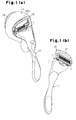
- an oscillating razor 1 is provided with a razor head 2.
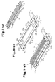
- the razor head 2 is provided with a blade member 3 made up of four blade bodies 4 and a base 7, a blade base member 5 arranged on the back side of the razor head 2, and a top member 6 arranged on the front side of the razor head 2.
- the blade body 4 is made of a metal such as martensite stainless steel.
- the thickness of the blade body 4 is set, for example, in a range between 0.05 mm and 0.3 mm, inclusive.
- the base 7 is made of a metal such as austenite stainless steel.
- the base 7 is formed, for example, by press-working a metal plate having a thickness of 0.1 mm to 0.5 mm.
- the base 7 is provided with a placing base 8 as a placing body made up of a pair of leaf springs 9 and a blade body supporting portion 10 installed between both leaf springs 9.
- the placing body is a supporting edge portion disposed at both side edges of the base 7.
- Each of the leaf springs 9 is provided with a supporting plate 11 extending in the longitudinal direction (Y direction given in Fig. 6 ) of the blade body 4 and a leg plate 12 as a leg portion which is bent from both end portions of the supporting plate 11 to the blade base member 5.
- a deflection allowance space 13 is disposed between the supporting plate 11 and both leg plates 12 (refer to Fig. 5(a) ).
- the base 7 is about 9 mm in width and about 34 mm in the entire length.
- the blade body supporting portion 10 is made up of a blade body attaching plate 14 as a blade body attaching portion having four step plates 16 and a plurality of installed arm portions 15 projected downward from both side edges of the blade body attaching plate 14.
- Each of the step plates 16 is extended in the Y direction and also arranged in a staircase pattern along the front-back direction (the Z direction given in Fig. 5 ) orthogonal to the Y direction.
- a plurality of through holes 17 extending in the Y direction are disposed between adjacent step plates 16.
- Each of the through holes 17 is arranged in the Y direction. With the strength of the base 7 taken into account, the closer to the center of the base 7, the shorter the entire length of the through holes 17 becomes.
- Each of the installed arm portions 15 is disposed in the Y direction at both side edge portions of the blade body attaching plate 14.
- Each of the installed arm portions 15 is bent toward the supporting plate 11 at the end portion thereof and also formed integrally with the supporting plate 11. Therefore, a space is formed inside the blade body attaching plate 14.
- a debris discharge hole 18 is disposed inside the placing base 8.
- the debris discharge hole 18 is opened outside the placing base 8 via a back opening 19 disposed on the back side of the placing base 8 and a front opening 20 disposed on the front side of the placing base 8.
- the back opening 19 is on a plane including both end portions 12a of each of leg plates 12, and a space enclosed by four end portions 12a of both leg plates 12 (refer to Fig. 2 ).
- the front opening 20 is a space located outside each through hole 17 of the blade body attaching plate 14 as well as both side edges and both end portions of the blade body attaching plate 14.
- the debris discharge hole 18 is opened outside the placing base 8 at both side edges and both end portions of the placing base 8 as well.
- the blade body 4 extending in the Y direction is placed on each of the step plates 16 and attached thereto by laser welding.
- Each of the blade bodies 4 is attached to each of the step plates 16, thereby arranged in a staircase pattern on the blade body attaching plate 14.
- a cutting edge 4a of each blade body 4 is projected forward from each of the step plates 16.
- the cutting edge 4a of the blade body 4 on the back side is brought closer to a back edge portion 4b of the blade body 4 on the front side. Therefore, a clearance 21 is formed between adjacent blade bodies 4.
- the clearance 21 faces each of the through holes 17 on the blade body attaching plate 14.
- the blade base member 5 is made up of a bottom base 22 and a base plate 23 arranged on the bottom base 22.
- the bottom base 22 is made of plastic and the base plate 23 is made of aluminum.
- the thickness of the base plate 23 is about 0.3 mm.
- the bottom base 22 is provided with a debris discharge hole 25 inside a frame portion 24.
- the frame portion 24 is made up of a front frame portion 24a, a back frame portion 24b, a left frame portion 24c, and right frame portion 24d as edge portions. Stoppers 24e projecting toward the blade body attaching plate 14 are disposed respectively at the inner edges of the left frame portion 24c and the right frame portion 24d.
- the base plate 23 is provided with a through hole 27 as a debris discharge hole inside a frame portion 26.
- the frame portion 26 is made up of a front frame portion 26a, a back frame portion 26b, a left frame portion 26c, and a right frame portion 26d.
- the frame portion 26 of the base plate 23 is superimposed on the frame portion 24 of the bottom base 22, and the through hole 27 of the base plate 23 is superimposed on the debris discharge hole 25 of the bottom base 22.
- the top member 6 is made of plastic.
- the top member 6 is provided with a blade body exposure hole 29 inside a frame portion 28.
- the frame portion 28 is made up of a front frame portion 28a, a back frame portion 28b, a left frame portion 28c, and a right frame portion 28d as edge portions.
- an inner wall 29a closer to both end portions of the top member 6 is formed along a circular arc expanding outwardly.
- a shaving aid is attached to the front frame portion 28a.
- a plurality of positioning recesses 30a are disposed in the vicinity of both end portions of the bottom base 2. Further, a plurality of notches 31a are disposed on the front and back frame portions 24a, 24b of the bottom base 2. On the other hand, a plurality of positioning projections 30b to be engaged with each of the positioning recesses 30a are disposed in the vicinity of both end portions of the top member 6. Further, a notch 31b is disposed at a position facing each notch 31a at the front and back frame portions 28a, 28b of the top member 6.
- the positioning projections 30b engage with the positioning recesses 30a, by which the front and back frame portions 24a, 24b of the blade base member 5 are positioned with respect to the front and back frame portions 28a, 28b of the top member 6.
- each of the notches 31a of the blade base member 5 is in alignment with each of the notches 31b of the top member 6 to form a plurality of attachment holes 31.
- an instant adhesive agent is poured into the attachment holes 31, by which the blade base member 5 is bonded to the top member 6.
- the leaf springs 9 on the base 7 are placed on the front and back frame portions 26a, 26b on the base plate 23 of the blade base member 5 at both end portions of the leg plate 12. Further, the leaf springs 9 are arranged at clearances 32 between the front and back frame portions 24a, 24b of the bottom base 22 and the front and back frame portions 28a, 28b of the top member 6. Both end portions of each blade body 4 are arranged between the left and right frame portions 24c, 24d of the bottom base 22 and the left and right frame portions 28c, 28d of the top member 6 on the blade body supporting portion 10. Both end portions of each blade body 4 are pressed to the left and right frame portions 28c, 28d of the top member 6 by an elastic force of each of the leaf springs 9.
- each blade body 4 is in close proximity to a shaving tangential plane 34 including each of skin-surface contact portions 33 disposed on the front and back frame portions 28a, 28b of the top member 6. Further, a plane including the cutting edge 4a and the back edge portion 4b of each blade body 4 is inclined with respect to the shaving tangential plane 34.
- Each blade body 4 is movable against an elastic force of each of the leaf springs 9 in the Z direction orthogonal to the shaving tangential plane 34, together with the blade body supporting portion 10.
- the debris discharge hole 18 inside the placing base 8 communicates with the through hole 27 of the base plate 23 and the debris discharge hole 25 of the bottom base 22 via the back opening 19, and also communicates with the blade body exposure hole 29 of the top member 6 via the front opening 20.
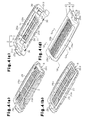
- the blade member 3 When assembling the top member 6, the blade member 3, and the blade base member 5, first, as shown in Fig. 4(a) , the blade member 3 is arranged inside the top member 6. Thereafter, as shown in Fig. 4(b) , the base plate 23 is arranged so as to be superimposed on the blade member 3 inside the top member 6. Then, as shown in Fig. 4(c) , the bottom base 22 is superimposed on the base plate 23 to assemble each of these members integrally. 5
- the shaving aid member 35 is provided with a base member 36 made of plastic, and a shaving aid 37 (for example, a porous body such as sponge soaked with cream) is fitted into the surface of the base member 36.
- the base member 36 is provided with an arm portion 38 at both end portions.
- One of the arm portions 38 is provided with a cantilever-type leaf spring 39 on a surface facing the other of the arm portions 38.
- the base member 36 and the shaving aid 37 are arranged behind the razor head 2.
- the base member 36 is supported via both arm portions 38 at both end portions of the razor head 2 so as to rotatable about the axial line 38a. Therefore, the shaving aid member 35 is swingable against an elastic force of the leaf spring 39 in a thickness direction of the razor head 2 (Z direction).
- the holder 40 is provided with a head 41.
- a supporting arm 42 and a pusher 43 are projected as arm portions from both side portions of the head 41.
- the bottom base 22 of the blade base member 5 is provided with recesses 44 as supporting portions on the back sides of the left and right frame portions 24c, 24d.
- the debris discharge hole 25 is disposed between the recesses 44.
- the oscillating razor 1 is retained on a wall surface via a hook 45 shown in Fig. 1(a) , when not in use.
- the hook 45 is provided with a suction cup 46 for adhering on a wall surface or the like and a cover 45a for preventing the razor head 2 from being splashed with water.
- the oscillating razor 1 is retained in a state where the head 41 of the holder 40 is hooked on the hook 45 to accommodate the razor head 2 inside the cover 45a.
- a clearance G between the blade body attaching plate 14 and both stoppers 24e is preferably set in a range of 0.1 mm to 1.2 mm. In the present embodiment, since the clearance G is set to be 0.5 mm, the blade body attaching plate 14 is movable in the Z direction only by the distance of the clearance G.
- the blade body attaching plate 14 is brought into contact with both stoppers 24e, by which the movement of each of the blade bodies 4 is restricted (refer to Fig. 3(b) ). It is preferable that on application of a force of 80 gf to 140 gf to the blade body attaching plate 14 in the Z direction orthogonal to the shaving tangential plane 34, the blade body 4 moves only by about 0.3 mm and on application of a force of 110 gf to 170 gf, the blade body 4 moves only by about 0.5 mm.
- Debris made by each of the blade bodies 4 are taken into the debris discharge hole 18 via the front opening 20 of the blade member 3 and then discharged via the back opening 19 from the debris discharge hole 25 of the blade base member 5.
- the holder may be formed integrally with the bottom base of the razor head.
- the skin-surface contact portion may be disposed on the blade base member, not on the top member. Further, one of a pair of skin-surface contact portions disposed on the top member may be omitted, and the skin-surface contact portion may be disposed on the blade base member.
- the leaf spring may be disposed not only on both edges of the placing base but also on both ends of the placing base. Further, the leaf springs on both edges of the placing base may be removed, and disposed on both ends of the placing base.
- an elastic body such as a coil spring or rubber may be used.
- a plurality of rods may be arrayed in a lattice form, and both ends of each rod may be bent to form a base.
- each of the leaf springs may be changed in width and thickness, so that the leaf springs are adjusted for spring constant. Further, leaf springs different in spring constant may be used to make different a distance at which each blade body can move.
- the cutting edge may be provided not only on the front side edge of each blade body but also at the back side edge. In this instance, the cutting edge at the back side edge of each blade body may be exposed.
- each step plate may be different between the front part and the back part of the blade body attaching plate.
- each of the blade bodies may be arranged so that the cutting edge is inclined forward at the front part of the blade body attaching plate and also exposed at the blade body exposure hole of the top member, whereas the cutting edge is inclined backward at the back part of the blade body attaching plate and also exposed at the blade body exposure hole of the top member.
- the number of blade bodies may be changed to five, six or eight. In this instance, a predetermined number of blade bodies are arranged at the front part of the blade body attaching plate and a remaining number of the blade bodies are arranged at the back part of the blade body attaching plate.
- the blade body attaching plate may be divided into two parts on the front side and the back side, and assembled.
Landscapes
- Life Sciences & Earth Sciences (AREA)
- Forests & Forestry (AREA)
- Engineering & Computer Science (AREA)
- Mechanical Engineering (AREA)
- Dry Shavers And Clippers (AREA)
Applications Claiming Priority (2)
| Application Number | Priority Date | Filing Date | Title |
|---|---|---|---|
| JP2006036664A JP4950506B2 (ja) | 2006-02-14 | 2006-02-14 | 剃刀 |
| PCT/JP2007/052559 WO2007094336A1 (fr) | 2006-02-14 | 2007-02-14 | Rasoir |
Publications (3)
| Publication Number | Publication Date |
|---|---|
| EP1990143A1 true EP1990143A1 (fr) | 2008-11-12 |
| EP1990143A4 EP1990143A4 (fr) | 2010-03-24 |
| EP1990143B1 EP1990143B1 (fr) | 2011-09-28 |
Family
ID=38371514
Family Applications (1)
| Application Number | Title | Priority Date | Filing Date |
|---|---|---|---|
| EP07714137A Ceased EP1990143B1 (fr) | 2006-02-14 | 2007-02-14 | Rasoir |
Country Status (4)
| Country | Link |
|---|---|
| US (1) | US8046920B2 (fr) |
| EP (1) | EP1990143B1 (fr) |
| JP (1) | JP4950506B2 (fr) |
| WO (1) | WO2007094336A1 (fr) |
Cited By (6)
| Publication number | Priority date | Publication date | Assignee | Title |
|---|---|---|---|---|
| US7992304B2 (en) * | 2006-02-14 | 2011-08-09 | Kai R&D Center Co., Ltd. | Razor |
| US8046920B2 (en) | 2006-02-14 | 2011-11-01 | Kai R&D Center Co., Ltd. | Razor |
| US8104179B2 (en) | 2006-02-14 | 2012-01-31 | Kai R&D Center Co., Ltd. | Razor |
| WO2017041845A1 (fr) * | 2015-09-09 | 2017-03-16 | Beiersdorf Aktiengesellschaft | Rasoir de sécurité et unité de lames pour ledit rasoir |
| EP3075498A4 (fr) * | 2013-11-27 | 2017-10-11 | Kai R & D Center Co., Ltd. | Rasoir |
| EP3175959A4 (fr) * | 2014-07-31 | 2018-02-14 | Kai R & D Center Co., Ltd. | Rasoir possédant un dispositif d'aide au rasage fixé |
Families Citing this family (19)
| Publication number | Priority date | Publication date | Assignee | Title |
|---|---|---|---|---|
| JP5010896B2 (ja) | 2006-10-31 | 2012-08-29 | 株式会社貝印刃物開発センター | 剃刀 |
| US8024863B2 (en) * | 2007-11-02 | 2011-09-27 | The Gillette Company | Conforming wet shaving razor |
| JP5364157B2 (ja) * | 2008-05-01 | 2013-12-11 | エバレデイ バツテリ カンパニー インコーポレーテツド | 分離可能な潤滑部 |
| JP5465869B2 (ja) | 2008-12-05 | 2014-04-09 | 株式会社貝印刃物開発センター | 替刃式剃刀 |
| JP5746197B2 (ja) * | 2009-10-20 | 2015-07-08 | エバレデイ バツテリ カンパニー インコーポレーテツド | 湿式シェービング器具のための潤滑剤箱 |
| US9757870B2 (en) * | 2012-12-21 | 2017-09-12 | Bic Violex S.A. | Shaver |
| WO2015090385A1 (fr) | 2013-12-18 | 2015-06-25 | Bic-Violex Sa | Cartouche de lame de rasage |
| CN109414828B (zh) | 2016-03-18 | 2020-12-18 | 个人护理市场及调研公司 | 剃刀盒 |
| USD816907S1 (en) | 2016-03-18 | 2018-05-01 | Personal Care Marketing and Research International | Razor frame |
| JP6992010B2 (ja) * | 2016-07-06 | 2022-01-13 | ビック・バイオレクス・エス・エー | カミソリシステム |
| US9993931B1 (en) | 2016-11-23 | 2018-06-12 | Personal Care Marketing And Research, Inc. | Razor docking and pivot |
| CN109227823A (zh) * | 2018-11-23 | 2019-01-18 | 徐震 | 一种手持电刨及其应用方法 |
| CN109262663A (zh) * | 2018-11-29 | 2019-01-25 | 中山佐客护理用品有限公司 | 剃须刀头以及剃须刀 |
| USD884970S1 (en) | 2019-02-27 | 2020-05-19 | PCMR International Ltd. | Razor cartridge guard |
| USD884969S1 (en) | 2019-02-27 | 2020-05-19 | Pcmr International Ltd | Combined razor cartridge guard and docking |
| USD884971S1 (en) | 2019-02-27 | 2020-05-19 | Pcmr International Ltd | Razor cartridge |
| US11000960B1 (en) * | 2020-11-16 | 2021-05-11 | Personal Care Marketing And Research, Inc. | Razor exposure |
| DE102020130698A1 (de) | 2020-11-20 | 2022-05-25 | LORD International Co. | Klingeneinheit für einen Nassrasierer |
| JP7595265B2 (ja) * | 2021-03-30 | 2024-12-06 | パナソニックIpマネジメント株式会社 | 電気かみそり |
Family Cites Families (66)
| Publication number | Priority date | Publication date | Assignee | Title |
|---|---|---|---|---|
| US3940853A (en) | 1974-04-19 | 1976-03-02 | The Gillette Company | Shaving unit with blade tensioning means |
| GB1591095A (en) | 1976-11-16 | 1981-06-17 | Wilkinson Sword Ltd | Shaving units |
| US4337575A (en) * | 1980-08-07 | 1982-07-06 | The Gillette Company | Razor blade assembly |
| US4324041A (en) * | 1980-08-07 | 1982-04-13 | The Gillette Company | Razor blade assembly |
| US4403412A (en) * | 1980-08-07 | 1983-09-13 | The Gillette Company | Razor blade assembly |
| US4403413A (en) * | 1980-10-06 | 1983-09-13 | The Gillette Company | Shaving implement |
| GB2131337B (en) | 1982-12-07 | 1985-10-30 | Gillette Co | Safety razors |
| JPS6047469A (ja) | 1983-08-25 | 1985-03-14 | Matsushita Electronics Corp | 半導体装置 |
| US4774765A (en) * | 1986-09-02 | 1988-10-04 | Warner-Lambert Company | Blade assembly featuring variable span |
| US4709477A (en) * | 1986-09-02 | 1987-12-01 | Warner-Lambert Company | Blade assembly featuring variable span |
| GB8712785D0 (en) | 1987-06-01 | 1987-07-08 | Gillette Co | Blade units |
| DE8910490U1 (de) | 1989-09-02 | 1991-01-10 | Wilkinson Sword GmbH, 5650 Solingen | Rasierapparatekopf eines Naßrasierapparates |
| GB9006782D0 (en) | 1990-03-27 | 1990-05-23 | Gillette Co | Safety razors and blade units therefor |
| US5416974A (en) | 1990-03-27 | 1995-05-23 | The Gillette Company | Safety razors and blade units therefor |
| CA2063993C (fr) | 1990-06-11 | 1999-08-03 | Graham John Simms | Rasoir |
| JPH0755268B2 (ja) | 1991-01-14 | 1995-06-14 | 株式会社貝印刃物開発センター | 安全かみそり刃組立体 |
| JPH0685828B2 (ja) | 1991-01-16 | 1994-11-02 | 株式会社貝印刃物開発センター | 安全かみそり刃組立体 |
| JPH0755267B2 (ja) | 1991-01-16 | 1995-06-14 | 株式会社貝印刃物開発センター | 安全かみそり |
| US5070612A (en) * | 1991-05-06 | 1991-12-10 | Michael Abatemarco | Razor blade assembly |
| JP2659629B2 (ja) | 1991-06-07 | 1997-09-30 | 株式会社貝印刃物開発センター | 剃刀の刃支持ヘッド |
| JP2659628B2 (ja) | 1991-06-07 | 1997-09-30 | 株式会社貝印刃物開発センター | 剃刀の刃支持ヘッド |
| DE9108213U1 (de) * | 1991-07-03 | 1992-10-29 | Wilkinson Sword GmbH, 5650 Solingen | Rasierapparatekopf, insbesondere Rasierklingeneinheit eines Naßrasierapparates |
| DE9108212U1 (de) | 1991-07-03 | 1992-10-29 | Wilkinson Sword GmbH, 5650 Solingen | Rasierapparatekopf, insbesondere Rasierklingeneinheit eines Naßrasierapparates |
| DE9108214U1 (de) * | 1991-07-03 | 1992-10-29 | Wilkinson Sword GmbH, 5650 Solingen | Rasierapparatekopf, insbesondere Rasierklingeneinheit eines Naßrasierapparates |
| EP0594681B1 (fr) | 1991-07-18 | 1998-04-29 | Warner-Lambert Company | Tete de rasoir a geometrie variable |
| GB2264888B (en) | 1992-03-06 | 1995-01-25 | Wilkinson Sword Gmbh | Razor head with flow passages |
| US5377409A (en) * | 1992-10-08 | 1995-01-03 | Warner-Lambert Company | One-push cleaning mechanism for flexible wet-shaving razor unit |
| JP2963824B2 (ja) | 1992-10-20 | 1999-10-18 | 株式会社貝印刃物開発センター | 刃体可動式安全剃刀 |
| AU5551994A (en) | 1992-11-09 | 1994-06-08 | Warner-Lambert Company | Insert molded dynamic shaving system |
| US5546660A (en) | 1994-09-30 | 1996-08-20 | Warner-Lambert Company | Dynamic razor head |
| US6295734B1 (en) * | 1995-03-23 | 2001-10-02 | The Gillette Company | Safety razors |
| GB9505917D0 (en) | 1995-03-23 | 1995-05-10 | Gillette Co | Safety razors |
| US5666729A (en) | 1995-04-10 | 1997-09-16 | Warner-Lambert Company | Suspended blade shaving system |
| WO1997035693A2 (fr) * | 1996-03-27 | 1997-10-02 | Warner-Lambert Company | Dispositif de rasage a forces de rasage uniformes |
| GB9616402D0 (en) * | 1996-08-05 | 1996-09-25 | Gillette Co | Safety razors |
| US7200937B2 (en) | 1997-01-17 | 2007-04-10 | Eveready Battery Company, Inc. | Razor head with moveable blade package |
| CA2223161A1 (fr) * | 1997-01-17 | 1998-07-17 | Warner-Lambert Company | Tetes de rasoir pourvues de lames flexibles independantes |
| US5822862A (en) | 1997-01-17 | 1998-10-20 | Warner-Lambert Co. | Suspended blade shaving system |
| GB9703293D0 (en) | 1997-02-18 | 1997-04-09 | Gillette Co | Safety razors |
| US20030159291A1 (en) * | 1997-07-25 | 2003-08-28 | Gregory Clark | Shaving system with uniform shaving forces |
| JP3209975B2 (ja) | 1999-03-18 | 2001-09-17 | 株式会社貝印刃物開発センター | 安全かみそり |
| US20040118250A1 (en) * | 1999-04-23 | 2004-06-24 | The Gillette Company, A Delaware Corporation | Safety razor |
| JP3515024B2 (ja) | 1999-09-17 | 2004-04-05 | 株式会社貝印刃物開発センター | 安全かみそり |
| KR100669144B1 (ko) * | 1999-11-29 | 2007-01-15 | 코닌클리케 필립스 일렉트로닉스 엔.브이. | 서브-프레임과 메인 프레임을 갖는 면도 헤드가 구비된면도기 |
| JP4598920B2 (ja) | 2000-05-29 | 2010-12-15 | 株式会社貝印刃物開発センター | 三枚刃剃刀ヘッドにおける刃体挟着構造 |
| US20040020053A1 (en) * | 2000-10-16 | 2004-02-05 | The Gillette Company | Safety razors |
| US20030046819A1 (en) | 2001-01-17 | 2003-03-13 | Frank Ferraro | Razor assembly and cartridge with wash-through holes |
| DE60218487T2 (de) | 2001-07-17 | 2007-10-31 | Kai R & D Center Co., Ltd. | Sicherheits-rasierapparat |
| ATE433840T1 (de) * | 2002-01-30 | 2009-07-15 | Eveready Battery Inc | Rasierklingeneinheit |
| US20040128835A1 (en) * | 2002-10-21 | 2004-07-08 | Eveready Battery Company, Inc. | Bidirectional shaving cartridge and razor including same |
| US20040255467A1 (en) * | 2003-01-28 | 2004-12-23 | Eveready Battery Company, Inc. | Razor blade platform and razor cartridge using same |
| US7111401B2 (en) * | 2003-02-04 | 2006-09-26 | Eveready Battery Company, Inc. | Razor head having skin controlling means |
| JP2006518228A (ja) | 2003-02-19 | 2006-08-10 | エバレディ バッテリー カンパニー インコーポレーテッド | マルチブレードレザーカートリッジ |
| CN1890066B (zh) * | 2003-12-02 | 2011-07-13 | 皇家飞利浦电子股份有限公司 | 剃削头以及包括该剃削头的剃削设备 |
| US7103976B2 (en) * | 2004-02-06 | 2006-09-12 | Eveready Battery Company, Inc. | Razor assembly |
| US7621203B2 (en) | 2004-02-09 | 2009-11-24 | The Gillette Company | Shaving razors, and blade subassemblies therefor and methods of manufacture |
| JP4921747B2 (ja) * | 2005-09-09 | 2012-04-25 | 株式会社貝印刃物開発センター | 剃刀 |
| JP4939785B2 (ja) * | 2005-09-09 | 2012-05-30 | 株式会社貝印刃物開発センター | 首振り式剃刀 |
| JP4950507B2 (ja) | 2006-02-14 | 2012-06-13 | 株式会社貝印刃物開発センター | 剃刀 |
| JP4950506B2 (ja) | 2006-02-14 | 2012-06-13 | 株式会社貝印刃物開発センター | 剃刀 |
| JP4977374B2 (ja) | 2006-02-14 | 2012-07-18 | 株式会社貝印刃物開発センター | 剃刀 |
| US8443519B2 (en) * | 2006-09-15 | 2013-05-21 | The Gillette Company | Blade supports for use in shaving systems |
| JP5010896B2 (ja) | 2006-10-31 | 2012-08-29 | 株式会社貝印刃物開発センター | 剃刀 |
| US20080256800A1 (en) * | 2007-04-20 | 2008-10-23 | Roy Nicoll | Razor cartridge assembly with movable face |
| US8650758B2 (en) * | 2007-11-02 | 2014-02-18 | The Gillette Company | Razor blade assembly pre-form |
| RU2479416C2 (ru) | 2008-09-29 | 2013-04-20 | Дзе Жиллетт Компани | Бритвенные приборы и картриджи для бритвенных приборов с уменьшенным совокупным расстоянием между лезвиями |
-
2006
- 2006-02-14 JP JP2006036664A patent/JP4950506B2/ja not_active Expired - Lifetime
-
2007
- 2007-02-14 US US12/223,870 patent/US8046920B2/en active Active
- 2007-02-14 EP EP07714137A patent/EP1990143B1/fr not_active Ceased
- 2007-02-14 WO PCT/JP2007/052559 patent/WO2007094336A1/fr not_active Ceased
Cited By (9)
| Publication number | Priority date | Publication date | Assignee | Title |
|---|---|---|---|---|
| US7992304B2 (en) * | 2006-02-14 | 2011-08-09 | Kai R&D Center Co., Ltd. | Razor |
| US8046920B2 (en) | 2006-02-14 | 2011-11-01 | Kai R&D Center Co., Ltd. | Razor |
| US8104179B2 (en) | 2006-02-14 | 2012-01-31 | Kai R&D Center Co., Ltd. | Razor |
| EP3075498A4 (fr) * | 2013-11-27 | 2017-10-11 | Kai R & D Center Co., Ltd. | Rasoir |
| US10183408B2 (en) | 2013-11-27 | 2019-01-22 | Kai R&D Center Co., Ltd. | Razor |
| EP3175959A4 (fr) * | 2014-07-31 | 2018-02-14 | Kai R & D Center Co., Ltd. | Rasoir possédant un dispositif d'aide au rasage fixé |
| US10252432B2 (en) | 2014-07-31 | 2019-04-09 | Kai R&D Center Co., Ltd. | Razor having attached shaving aid |
| WO2017041845A1 (fr) * | 2015-09-09 | 2017-03-16 | Beiersdorf Aktiengesellschaft | Rasoir de sécurité et unité de lames pour ledit rasoir |
| US10870212B2 (en) | 2015-09-09 | 2020-12-22 | Beiersdorf Ag | Safety razor and blade unit for safety razor |
Also Published As
| Publication number | Publication date |
|---|---|
| EP1990143B1 (fr) | 2011-09-28 |
| JP4950506B2 (ja) | 2012-06-13 |
| US20100229397A1 (en) | 2010-09-16 |
| EP1990143A4 (fr) | 2010-03-24 |
| WO2007094336A1 (fr) | 2007-08-23 |
| US8046920B2 (en) | 2011-11-01 |
| JP2007215590A (ja) | 2007-08-30 |
Similar Documents
| Publication | Publication Date | Title |
|---|---|---|
| EP1990143B1 (fr) | Rasoir | |
| EP1985418B1 (fr) | Rasoir | |
| EP1718438B1 (fr) | Rasoirs et leurs sous-ensembles de lames, et procedes de fabrication associes | |
| EP1990142B1 (fr) | Rasoir | |
| US6035537A (en) | Razor cartridge with metal clip retaining blades | |
| JP5518710B2 (ja) | 刃ユニット付勢部材を有するカミソリ | |
| CN107995887B (zh) | 剃刀刀片架 | |
| JP4913146B2 (ja) | レザー・カートリッジ用のブレード取付け部材 | |
| JP4939785B2 (ja) | 首振り式剃刀 | |
| KR20060132904A (ko) | 면도기 및 그 제조 방법 및 면도기용 부조립체 | |
| WO1999016592A1 (fr) | Cartouche de rasoir a lames mobiles | |
| KR100635590B1 (ko) | 전기 면도기 | |
| KR20180088899A (ko) | 면도기 및 면도 카트리지 | |
| EP3638467B1 (fr) | Cartouches de rasoir | |
| JP3942694B2 (ja) | 往復動式電気かみそりの内刃と往復動式電気かみそり | |
| MXPA06009027A (en) | Shaving razors, and blade subassemblies therefor and methods of manufacture | |
| JPH11128564A (ja) | 電気かみそり |
Legal Events
| Date | Code | Title | Description |
|---|---|---|---|
| PUAI | Public reference made under article 153(3) epc to a published international application that has entered the european phase |
Free format text: ORIGINAL CODE: 0009012 |
|
| 17P | Request for examination filed |
Effective date: 20080819 |
|
| AK | Designated contracting states |
Kind code of ref document: A1 Designated state(s): DE FR GB |
|
| RBV | Designated contracting states (corrected) |
Designated state(s): DE FR GB |
|
| DAX | Request for extension of the european patent (deleted) | ||
| RBV | Designated contracting states (corrected) |
Designated state(s): DE FR GB |
|
| A4 | Supplementary search report drawn up and despatched |
Effective date: 20100224 |
|
| 17Q | First examination report despatched |
Effective date: 20100707 |
|
| GRAP | Despatch of communication of intention to grant a patent |
Free format text: ORIGINAL CODE: EPIDOSNIGR1 |
|
| GRAS | Grant fee paid |
Free format text: ORIGINAL CODE: EPIDOSNIGR3 |
|
| GRAA | (expected) grant |
Free format text: ORIGINAL CODE: 0009210 |
|
| RIN1 | Information on inventor provided before grant (corrected) |
Inventor name: NAKASUKA, HIROYUKI |
|
| AK | Designated contracting states |
Kind code of ref document: B1 Designated state(s): DE FR GB |
|
| REG | Reference to a national code |
Ref country code: GB Ref legal event code: FG4D |
|
| REG | Reference to a national code |
Ref country code: DE Ref legal event code: R096 Ref document number: 602007017507 Country of ref document: DE Effective date: 20111201 |
|
| PLBE | No opposition filed within time limit |
Free format text: ORIGINAL CODE: 0009261 |
|
| STAA | Information on the status of an ep patent application or granted ep patent |
Free format text: STATUS: NO OPPOSITION FILED WITHIN TIME LIMIT |
|
| 26N | No opposition filed |
Effective date: 20120629 |
|
| REG | Reference to a national code |
Ref country code: DE Ref legal event code: R097 Ref document number: 602007017507 Country of ref document: DE Effective date: 20120629 |
|
| REG | Reference to a national code |
Ref country code: FR Ref legal event code: PLFP Year of fee payment: 10 |
|
| REG | Reference to a national code |
Ref country code: FR Ref legal event code: PLFP Year of fee payment: 11 |
|
| REG | Reference to a national code |
Ref country code: FR Ref legal event code: PLFP Year of fee payment: 12 |
|
| PGFP | Annual fee paid to national office [announced via postgrant information from national office to epo] |
Ref country code: FR Payment date: 20230217 Year of fee payment: 17 |
|
| PGFP | Annual fee paid to national office [announced via postgrant information from national office to epo] |
Ref country code: GB Payment date: 20230221 Year of fee payment: 17 Ref country code: DE Payment date: 20230216 Year of fee payment: 17 |
|
| REG | Reference to a national code |
Ref country code: DE Ref legal event code: R119 Ref document number: 602007017507 Country of ref document: DE |
|
| GBPC | Gb: european patent ceased through non-payment of renewal fee |
Effective date: 20240214 |
|
| PG25 | Lapsed in a contracting state [announced via postgrant information from national office to epo] |
Ref country code: DE Free format text: LAPSE BECAUSE OF NON-PAYMENT OF DUE FEES Effective date: 20240903 |
|
| PG25 | Lapsed in a contracting state [announced via postgrant information from national office to epo] |
Ref country code: GB Free format text: LAPSE BECAUSE OF NON-PAYMENT OF DUE FEES Effective date: 20240214 |
|
| PG25 | Lapsed in a contracting state [announced via postgrant information from national office to epo] |
Ref country code: FR Free format text: LAPSE BECAUSE OF NON-PAYMENT OF DUE FEES Effective date: 20240229 |
|
| PG25 | Lapsed in a contracting state [announced via postgrant information from national office to epo] |
Ref country code: GB Free format text: LAPSE BECAUSE OF NON-PAYMENT OF DUE FEES Effective date: 20240214 Ref country code: FR Free format text: LAPSE BECAUSE OF NON-PAYMENT OF DUE FEES Effective date: 20240229 Ref country code: DE Free format text: LAPSE BECAUSE OF NON-PAYMENT OF DUE FEES Effective date: 20240903 |