EP1990158A1 - Verfahren und Vorrichtung zur Verarbeitung von mindestens einer Ladung Holz - Google Patents
Verfahren und Vorrichtung zur Verarbeitung von mindestens einer Ladung Holz Download PDFInfo
- Publication number
- EP1990158A1 EP1990158A1 EP08305145A EP08305145A EP1990158A1 EP 1990158 A1 EP1990158 A1 EP 1990158A1 EP 08305145 A EP08305145 A EP 08305145A EP 08305145 A EP08305145 A EP 08305145A EP 1990158 A1 EP1990158 A1 EP 1990158A1
- Authority
- EP
- European Patent Office
- Prior art keywords
- wood
- load
- treatment
- receiving means
- tilting
- Prior art date
- Legal status (The legal status is an assumption and is not a legal conclusion. Google has not performed a legal analysis and makes no representation as to the accuracy of the status listed.)
- Withdrawn
Links
Images



Classifications
-
- B—PERFORMING OPERATIONS; TRANSPORTING
- B27—WORKING OR PRESERVING WOOD OR SIMILAR MATERIAL; NAILING OR STAPLING MACHINES IN GENERAL
- B27K—PROCESSES, APPARATUS OR SELECTION OF SUBSTANCES FOR IMPREGNATING, STAINING, DYEING, BLEACHING OF WOOD OR SIMILAR MATERIALS, OR TREATING OF WOOD OR SIMILAR MATERIALS WITH PERMEANT LIQUIDS, NOT OTHERWISE PROVIDED FOR; CHEMICAL OR PHYSICAL TREATMENT OF CORK, CANE, REED, STRAW OR SIMILAR MATERIALS
- B27K3/00—Impregnating wood, e.g. impregnation pretreatment, for example puncturing; Wood impregnation aids not directly involved in the impregnation process
- B27K3/02—Processes; Apparatus
- B27K3/0228—Spraying apparatus, e.g. tunnels
-
- B—PERFORMING OPERATIONS; TRANSPORTING
- B27—WORKING OR PRESERVING WOOD OR SIMILAR MATERIAL; NAILING OR STAPLING MACHINES IN GENERAL
- B27K—PROCESSES, APPARATUS OR SELECTION OF SUBSTANCES FOR IMPREGNATING, STAINING, DYEING, BLEACHING OF WOOD OR SIMILAR MATERIALS, OR TREATING OF WOOD OR SIMILAR MATERIALS WITH PERMEANT LIQUIDS, NOT OTHERWISE PROVIDED FOR; CHEMICAL OR PHYSICAL TREATMENT OF CORK, CANE, REED, STRAW OR SIMILAR MATERIALS
- B27K3/00—Impregnating wood, e.g. impregnation pretreatment, for example puncturing; Wood impregnation aids not directly involved in the impregnation process
- B27K3/02—Processes; Apparatus
- B27K3/0278—Processes; Apparatus involving an additional treatment during or after impregnation
- B27K3/0292—Processes; Apparatus involving an additional treatment during or after impregnation for improving fixation
Definitions
- the present invention relates to a method and a device for treating at least one load of wood.
- This invention relates to the field of manufacturing facilities designed to provide simultaneous processing of a large amount of wood pieces grouped together in at least one load of wood.
- Some of these devices take the form of a tray containing the treatment product in which is immersed the load of wood disposed on receiving means of this load.
- the tank of these devices contains, in fact, a large amount of treatment product (greater than 1000 liters) which, usually, contains harmful or even toxic chemical compounds for the human or even animal and dangerous species. for the environment.
- treatment product greater than 1000 liters
- the use of such a quantity of product is subject to particularly restrictive standards and an approval requiring lengthy and tedious steps.
- the present invention is intended to overcome the disadvantages of devices and methods of the state of the art by providing an improved method and an improved device for the treatment of wood loads by sprinkling.
- the tilting of the receiving means is provided around a tilting axis, as the case may be, parallel or forming an angle with one of the sides, more particularly with one of the longitudinal sides, receiving means.
- the method consists in providing, in addition, an inclination of the receiving means, more particularly of the enclosure containing these receiving means, by rotation about an axis of inclination distinct from the axis of tilting. these receiving means.
- This invention also relates to a device for treating at least one load of wood.
- This device is, in particular, designed to implement the method that is the subject of the invention, and is in the form of a chamber comprising, internally, on the one hand, means for receiving at least one such load wood, on the other hand, means for spraying the wood with a product for its treatment, characterized in that this device comprises, on the one hand, moving means for moving the means of receiving the wood inside the enclosure and, secondly, control means of this movement.
- the device comprises, on the one hand, tilt-mounting means of the receiving means, more particularly the enclosure containing these receiving means, by rotation about an axis of tilt distinct from the tilting axis of these receiving means and, secondly, control means of this inclination.
- the advantages of the process according to the invention consist in that the sprinkling of the load of flat wood makes it possible to treat in a large part this load of wood, or even the entirety of this load of wood.
- the flat treatment of this load of wood can significantly improve the quality of the treatment, particularly compared to a treatment of a load in an inclined position.
- the flat position advantageously allows to slow the path of the product inside the load, which allows more time for the product to act and to penetrate the wood.
- the treatment of all the faces of each piece of the wood load it can, advantageously and at least in part, be provided by a capillary phenomenon.
- the movement of the receiving means allows at least the dripping of the wood load.
- This draining advantageously makes it possible to complete and improve a dripping operation which operates imperfectly and longer, keeping the load of wood flat. It will be observed that the main purpose of this dripping is to drop back into the enclosure of the device the surplus of treatment product.
- the displacement of these reception means makes it possible, and advantageously, to flow the treatment product inside the wood load, especially to the heart, and completes, advantageously, the treatment with aspersion.
- the displacement of the receiving means advantageously makes it possible to modify the position of the wood load relative to the jets of the sprinkling means so as to allow these jets to spray other parts of this load of wood. .
- this displacement makes it possible to orient load of wood so that interstices formed between two pieces of wood load, are positioned in front of such a jet that can then spray the product inside the load of wood, until at the heart of this charge, this through such an interstice.
- the inclination of the receiving means and / or their tilting around a tilting axis forming an angle with one of the sides of these receiving means advantageously allows a flow of the product inside the load, but allows, also, to facilitate the draining of the load.
- Such a type of flow and dewatering has a particular advantage in the context of engineered wood parts having, for example, grooves, ribs, tongues or the like, more particularly those extending longitudinally.
- Another advantage is that the treatment of wood by spraying makes it possible to use a particularly small amount of treatment product (in this case less than 1000 liters) compared with an immersion treatment known in the state of the art. .
- the invention relates to the field of manufacturing facilities designed to ensure the simultaneous treatment of a large amount of wood pieces grouped together in at least one load of wood.
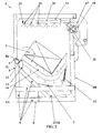
- the invention relates, more particularly, to a device 1 designed to ensure the treatment of at least one such load 2 of wood.
- Such a device 1 comprises an enclosure 3 inside which is disposed at least one load of wood 2 and constituted, on the one hand, by a box 4 adopting, substantially, the shape of a tray or the like and, d on the other hand, by a removable opening 5 (in particular a cover, a door or the like) able to close, in particular in a sealed manner, this box 4.
- a box 4 adopting, substantially, the shape of a tray or the like and, d on the other hand, by a removable opening 5 (in particular a cover, a door or the like) able to close, in particular in a sealed manner, this box 4.
- said box 4 of this enclosure 3 is delimited by longitudinal walls before 6A, rear 6B and lateral 6C as well as by a bottom 7 each of which may be constituted by at least one plate , in particular of metal type, more particularly by a plurality of assembled plates, in particular by welding.
- such a chamber 3 may be of the self-supporting type.
- the device 1 comprises, again, a chassis 8, in particular constituted by a assembly of tubular elements 9, defining a structure for receiving said enclosure 3.
- said enclosure 3, more particularly at least a portion of the plates 6 constituting this enclosure 3, can be attached to this frame 8, or even be secured to the latter 8, in particular by welding on a part of said elements tubular 9.
- said opening 5 which comprises said enclosure 3, it is slidably or tiltingly mounted on at least one wall 6 of the enclosure 3 and / or on the chassis 8 for the reception of this enclosure 3, this between an open position and a closed position of the casing 4 and, consequently, of the enclosure 3.
- Such sliding can be provided by means of sliding slides fitted to the opening 5 and / or some walls 6 of the enclosure 3, or the chassis 8 of the device 1 (solution not shown).
- a tilting it is provided around a substantially horizontal axis, preferably substantially parallel to the front walls 6A and / or rear 6B of the enclosure 3.
- such a tilt fitting of this opening 5 is formed on a wall 6 of said enclosure 3 (in particular on the rear wall 6B of this enclosure 3) or, and preferably as visible figure 2 , on the frame 8, more particularly on a tubular element 9 of this frame 8, in particular at the rear wall 6B of the enclosure 3.
- At least one load of wood 2 is disposed inside the enclosure 3 which comprises, then also and internally, on the one hand, means 10 for receiving this or these loads of wood 2 and, secondly, means 11 for spraying this or these wood loads 2 with a product for its treatment.
- the processing device 1 comprises means 12 for moving mounting means 10 for receiving the wood inside the enclosure 3.
- such means 12 for mounting in displacement can be designed to allow a displacement of the means 10 for receiving the wood in a movement describing a left path.
- FIG. 1 to 7 Another embodiment of the illustrated invention Figures 1 to 7 consists in that the means 12 for mounting in displacement are constituted by means 12 for mounting in tilting means 10 for receiving the wood inside the enclosure 3.
- Such tilt-mounting means 12 are, in fact, designed to allow a tilting of these receiving means 10 between, on the one hand, a position of loading and / or unloading of these receiving means 10 and, of on the other hand, at least one inclined position with respect to said loading / unloading position, this around at least one tilting axis B.
- the loading / unloading position of the receiving means 10 corresponds, more particularly, to a horizontal position of these receiving means 10 as visible on the figure 1 .
- Such loading / unloading is ensured in the open position of the opening 5 and, more particularly, at the front wall 6A of the enclosure 3, this by means of a handling machine, in particular constituted by a forklift or the like.
- a particular embodiment consists in that the load (s) 2 of wood can then be arranged (or, preferably, fagotées) on a pallet, in particular of standard type, able to be lifted by said handling machine for be, as the case may be, disposed on said receiving means 10 or removed therefrom 10.
- the tilting is provided around at least one tilting axis B.
- the means 12 of tilt mounting are designed to allow a tilting means of reception 10 around a tilting axis B1 parallel to one of the sides of these receiving means 10.
- this tilting axis B1 extends parallel to one of the longitudinal sides of said receiving means 10.
- a load of wood 2 extends substantially longitudinally and that it is then possible to define, for this load of wood 2, a longitudinal axis of extension which is preferably, parallel (or even confused) with an axis of symmetry of this load of wood 2.
- this load of wood 2 is arranged on the receiving means 10 so that its longitudinal axis of extension is substantially parallel to at least one longitudinal side of the receiving means 10, more particularly to the longitudinal side with respect to which the tilting axis B1 is itself parallel.
- Such an embodiment then advantageously makes it possible to tilt such a load of wood 2 along an axis B1 substantially parallel to the axis of longitudinal extension of this load of wood 2.
- Such an embodiment allows , then, a lateral dewatering of this load of wood 2, this in a direction substantially perpendicular to the axis of longitudinal extension of this load of wood 2.
- the tilt-mounting means 12 are designed to allow tilting of the receiving means 10 around a tilting axis B2; B3 forming an angle with one of the sides of the receiving means 10.
- this pivot axis B2; B3 forms an angle with one of the longitudinal sides of these receiving means 10.
- Such a second type of embodiment allows, then, to ensure a tilting of the wood load 2 along an axis B2; B3 at an angle to the axis of longitudinal extension of a wood load 2 disposed on these receiving means 10.
- this longitudinal extension axis describes, more particularly, a portion of the cone during the tilting of the means of reception 10.
- Such a second type of embodiment advantageously makes it possible to give the wood load 2 a combined tilting movement according to the width and the length of this load 2.
- the receiving means 10 adopt a substantially horizontal position so that the tilting axis B1; B2 then extends substantially horizontally.
- the tilting axis B3 of the receiving means 10 forms an angle with the plane in which the receiving means 10 extend in the loading / unloading position. This tilting axis B3 then extends at an angle to the horizontal.
- Such an embodiment advantageously makes it possible to accentuate the amplitude of the tilting of these reception means 10 with respect to the first embodiment of the second embodiment and, a fortiori, with respect to the first embodiment.
- the longitudinal side of the receiving means 10 (relative to which the tilting axis, as the case may be, is parallel B1 or forms an angle B2; B3) extends substantially parallel to the front wall 6A and / or the rear wall 6B of the enclosure 3, this in the loading / unloading position of these receiving means 10.
- Such an embodiment then makes it possible to tilt the load of wood 2 forwardly and / or rearwardly of the device 1.
- tilt-mounting means 12 makes it possible, advantageously, and after flat-spraying of such a load 2 of wood, to improve the dewatering of this load 2 of wood, this facilitating the flow of the product of treatment out of the latter 2.
- tilting advantageously allows a flow of the treatment product inside a load 2 of wood, especially to the heart, greatly improving the treatment of the pieces of wood, especially those not lying at the periphery of the load 2, in particular that arranged at the heart of such a load 2.
- the tilting makes it possible to modify the position of the load 2 of wood with respect to the spraying means 11 which are then capable of spraying other parts of this load 2 of wood, or even of spraying the product of treatment directly in interstices between two pieces of wood thus allowing this product to penetrate inside a load 2 of wood, including the heart thereof 2.
- a sprinkling can complement (more particularly in the form of one or more finishing passes) a sprinkling of such a load 2 flat to ensure, in the great majority (of the order of 95 %), the treatment of such a load of wood 2.
- the means 12 of tilt mounting are constituted by at least one support 13, more particularly defined by a yoke or the like, on which (which) the receiving means 10 are mounted in rotation around said tilting axis B1; B2; B3.
- such a support 13 can be made integral with a wall 6 of the enclosure 3 (more particularly of the front wall 6A of this enclosure 3) and / or of the chassis 8 for the reception of this enclosure 3, more particularly of a tubular element 9 which this frame 8 comprises, in particular at the level of the front wall 6A of this enclosure 3.
- the means 12 of tilt mounting are constituted by two supports 13, 13 ', one of which at least 13, 13' is made integral with a wall 6 of the enclosure 3 and / or chassis 8 as mentioned above.
- these supports 13, 13 ' are then implanted at the level of the device 1, so that they are aligned in a direction parallel to one of the sides (preferably one longitudinal side) receiving means 10, or even parallel with the longitudinal direction of extension of the enclosure 3.
- a preferred embodiment of visible embodiment figure 2 consists in that these two supports 13, 13 'are, again and preferably, aligned in a direction parallel to the longitudinal direction of extension of the enclosure 3 (direction, more particularly, parallel to the longitudinal walls 6A, 6B of this pregnant 3).
- the supports 13, 13 ' are located at the device 1 so as to be aligned in a direction at an angle to one of the sides (preferably a longitudinal side ) receiving means 10, or even with the longitudinal extension direction of the enclosure 3.
- first support 13 can then be implanted in proximity, at or on a longitudinal wall 6 (more particularly the front wall 6A) that comprises said enclosure 3 while the second support 13 'can, then, be implanted at a determined distance from this longitudinal wall 6.
- such a second support 13 ' can be implanted at the end of an arm extending from this longitudinal wall 6 and that includes the frame 8.
- Such arm can be designed so as to cross this longitudinal wall 6 and to extend inside the enclosure 3.
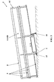
- such an arm is horizontal and / or parallel to the plane in which the receiving means 10 extend in the loading / unloading position as visible. figures 4 and 5 .
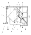
- such an arm is vertical and / or perpendicular to the plane in which the receiving means 10 extend in the loading / unloading position as visible. figures 6 and 7 .
- said supports 13, 13 ' are offset in altitude relative to the horizontal.
- a preferred embodiment visible Figures 4 to 7 consists in that these two supports 13, 13 'are, again and preferably, aligned in a direction forming an angle with the longitudinal direction of extension of the enclosure 3.
- the receiving means 10 are positioned over the supports 13, 13 'on which these receiving means 10 are mounted in a tilting manner.
- the first support 13 is positioned near the longitudinal edge of the receiving means 10, preferably below them 10.
- said second support 13 ' is then positioned beneath said receiving means 10 at a place judiciously determined so as to allow the reception means 10 to tilt properly inside the enclosure 3.
- the supports 13, 13 ' are positioned at a determined distance from the longitudinal edge of the receiving means 10, more particularly close to the vertical of the center of gravity of a load of wood 2 capable of being arranged on the receiving means 10, in the loading / unloading position of these receiving means 10.
- a preferred embodiment is that these supports 13, 13 'are, then, arranged on either side of such a vertical, in particular on either side of a vertical plane passing through this vertical and extending longitudinally with respect to the enclosure 3 and / or the load of wood 2.
- the above-mentioned tilt-mounting means 12 are completed by means 14 for controlling this tilting.
- a preferred embodiment of the visible invention figure 1 consists in that such control means 14 are constituted by a single cylinder or the like.
- Yet another characteristic of the invention consists in that the receiving means 10 are completed by means for maintaining at least a load 2 of wood on these receiving means 10, in the tilting position of the latter 10.
- such holding means are in the form of at least one stopper complementing the receiving means 10 and extending, substantially perpendicularly, from these receiving means 10 and at the level of free end of the latter 10, in particular opposite to that at which these receiving means 10 are mounted in tilting.
- said means for receiving 10 at least one load 2 of wood may be constituted by a support or the like, preferably made by assembling, in particular by welding, tubular elements, plus particularly of metallic type, as visible figures 1 , 2 , 4 , 5 , 6 and 7 .
- such a support is preferably designed so as to allow the passage of gripping members (forks or the like) that includes a handling machine.
- An additional feature of the invention consists in that the processing device 1 can, again, comprise means 15 for mounting in inclination of the receiving means 10.
- Such tilt-mounting means 15 are adapted to allow inclination of these receiving means 10 by rotation about an inclination axis I distinct from the tilting axis B1; B2; B3 of these reception means 10.
- this inclination axis I extends, on the one hand, parallel to the plane of the receiving means 10 in the loading / unloading position and, on the other hand, in a direction forming an angle with the tilting axis B1; B2; B3 of these reception means 10.
- Such an angle may be right in the case of the first type of embodiment mentioned above.
- this inclination axis I and this tilting axis B1; B2; B3 are vertically offset from one another and are not intersecting.
- a preferred embodiment consists in that the inclination axis I is substantially parallel to the side walls 6C of the enclosure 3.
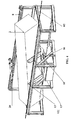
- tilt-mounting means 15 are constituted by inclination mounting means of the enclosure 3 with respect to the ground on which the treatment device 1 is arranged, or even (and preferably as visible figure 3 ) of the entire device 1 relative to the ground.
- tilt-mounting means 15 will find a particularly suitable application in the context of tilting means 12 according to the first embodiment without, however, being limited in this application and could also , be considered in the context of the second type of embodiment described above.
- tilting mounting means advantageously allow a flow of the treatment product along the length of the pieces when they are arranged on the receiving means 10 so as to extend longitudinally. inside the chamber 3, more particularly parallel to the front wall 6A and / or rear 6B.
- This flow allows a treatment of the wood in the heart of the load 2 and, on the other hand, facilitates the dewatering of the latter 2, more particularly in the final phase of treatment thereof 2.
- the tilt control means 14 and the inclination control means 16 may be constituted by a single control means, more particularly constituted by a jack or the like.
- the means 16 for controlling the inclination are, like the means 14 for controlling the tilting, constituted by a jack or the like.
- the device 1 comprises spraying means 11.
- a first embodiment consists in that these spraying means 11 are fixed inside the enclosure 3.
- the device 1 comprises means 17 for moving the sprinkling means 11 relative to the means 10 for receiving the wood 2.
- Such displacement mounting means 17 are designed to ensure the displacement of the spraying means 11 with respect to at least one load of wood 2 and, more particularly, so that these spraying means 11 can spray this or these loads. 2 on the whole length.
- such moving means 17 are constituted, on the one hand, by a carriage 18 receiving the spraying means 11 which adopt, more particularly, the form of sprinkler nozzles 19 implanted, in particular regularly spaced, at an arm 20 mounted on such a carriage 18 and extending, preferably horizontally, above the receiving means 10, more particularly above at least one load of wood 2 disposed over them.
- such sprinkling means 11 are located near such a load of wood 2 when it is in the loading / unloading position.
- these means 17 for mounting in displacement are constituted by a guide means 21 receiving said carriage 18 and, as the case may be, that comprises or that receives a wall 6 (preferably the rear wall 6B) of the enclosure 3 or the chassis 8 associated with this enclosure 3.
- Such a guide means 21 may be defined by at least one groove and / or at least one rib adapted to cooperate with rolling means (shoe, wheel or the like) that comprises said carriage 18.
- these displacement mounting means 17 are designed to ensure a displacement of the spraying means 11 substantially parallel to the front wall 6A and / or rear wall 6B of the enclosure 3.
- the displacement mounting means 17 allow, then, a sprinkling of such a load of wood 2 longitudinally.
- displacement mounting means 17 advantageously makes it possible to spray one or more wood loads 2 over the entire length while reducing the number of spray nozzles.
- the device 1 also comprises means for controlling these displacement mounting means 17.
- the device 1 further comprises means 22 for detecting the presence and / or at least one dimension of at least one wood load 2 of wood disposed on the receiving means 10.
- Such detection means 22 can then be designed to allow spraying only when a load of wood 2 is placed on the receiving means 10.
- these detection means 22 make it possible to detect at least one dimension of at least one such load of wood 2, more particularly the length and / or the width of such a load. of wood 2.
- the fact of detecting the width of such a wood load 2 advantageously makes it possible to activate only part (or all) of the spray nozzles of the sprinkler means 11 when the load of wood 2 s extends over at least part (or even all) of the width of the receiving means 10.
- the fact of detecting the length of at least one load of wood 2 advantageously makes it possible to limit the the spraying means 11 are moved so that they spray only the wood load (s) 2 disposed on the receiving means (10) and avoid spraying the product beyond this or these fillers (2), in particular on the one hand and else of such a load 2.
- the device 1 can manage the spraying means 11 (more particularly, the number of nozzles 19 that will spray the wood 2 and / or which of these nozzles 19 will actually spraying this wood 2) and / or the control means of the means 17 for mounting the spraying means 11 in displacement.
- such detection means 22 consist of at least one sensor, more particularly of ultrasonic type or the like.
- a particular embodiment of the invention consists in that such detection means 22 are associated with the spraying means 11, more particularly the arm 20 receiving the latter.
- the device 1 comprises means for drying a load of wood 2.
- Such drying means advantageously make it possible to shorten the treatment cycle of a wood load 2 and, consequently, to increase the number of treated wood loads 2 per day.
- drying means may consist of hot air batteries designed to inject hot air into the enclosure 3.
- the device 1 comprises means for supplying the spraying means 11 with treatment product. In the rest of the description, these means of supply will be qualified as main.
- Such supply means comprise a reservoir containing treatment product and a connected valve, on the one hand, to this reservoir and, on the other hand, to said means 11 for spraying.
- Such feed means are advantageously designed so as to ensure a gravity flow of the treatment product towards the sprinkler means 11.
- the treatment product is prepared by mixing a concentrate (of the treatment product) with a diluent (more particularly water), or even with at least one additive (especially a dye or other).
- a preferred embodiment of the invention consists in the fact that this mixing takes place by ensuring the flow, by gravity, in the reservoir, on the one hand, of the concentrate contained in a first container, on the other hand, the diluent contained in a second container, or even at least one additive contained in at least a third container, these containers (which comprises the device 1) being located upstream of the reservoir so as to allow a feed, preferably sequentially , of this tank by gravity.
- the content of these containers is determined so that the ratio of the volumes of these containers corresponds to the ratio of the volumes of the constituents (concentrate, diluent, or even at least one additive) of the treatment product.
- the tank may, in fact, comprise a plurality of level sensors able to control at least one valve to allow the flow in the tank, as the case may be, of the concentrate, diluent, or at least one additive.
- a first level sensor designed to detect the level reached by the concentrate which has flowed into the tank and to control the interruption of the flow of this concentrate ( more particularly by controlling the closing of a valve).
- a second sensor designed to detect the level reached by the mixture (concentrate + diluent) after diluent flow into the reservoir and to control the interruption of the flow of this diluent (more particularly by controlling the closing of a valve).
- a third sensor designed to detect the level reached by the mixture (concentrate + diluent + additive) after the flow of at least one additive in the tank and to control the interruption of the flow of this or these additives (more particularly by controlling the closing of a valve).
- these feed means can then be designed to allow the production of the mixture constituting the treatment product and / or the feeding of the spraying means 11 treatment product, this by gravity.
- Such an embodiment advantageously avoids the use of a pump which makes it possible to reduce the number of expensive components and, therefore, the total cost of the device 1.
- another embodiment may, again, consist of using at least one pump for ensuring the supply of the tank by one or more containers and / or the supply of the spraying means 11 by this tank.
- the device 1 comprises means 23 for collecting the treatment product flowing from the wood load 2 after sprinkling thereof 2.
- Such means 23 may consist of a sump 24 in which flows this treatment product.
- Such sump 24 is located at the bottom 7 of the enclosure 3 and can be made by assembling plates constituting the latter 3.
- this sump 24 may be equipped with means for detecting the level of product in this sump 24 and designed to control the above-mentioned supply valve of the spraying means 11.
- the device 1 comprises means (more particularly in the form of at least one pump or the like associated with a circulation circuit of treatment product) for supplying the spraying means 11 with the treatment product collected at the level of the means 23.
- feed means may also comprise means for purifying, diluting and concentrating the treatment product collected at this sump 24.
- Such feed means may then complement the main feed means described in more detail above.
- a preferred embodiment consists in that these management means are, at least in part, constituted by an automaton (in particular programmable) and / or by computer means, in particular a management software.
- the invention also relates to a method for the treatment (preferably simultaneously) of at least one load of wood 2 by spraying with a treatment product.
- This method consists in that at least one such load of wood 2 is disposed inside an enclosure 3 and flat on the aforementioned receiving means 10.
- This process consists, then, in that one proceeds to the treatment of the wood by sprinkling with the product of treatment and in that one ensures the displacement of the receiving means 10 of the wood inside the chamber 3 at least to cause the dewatering of the wood, or even to ensure the heart treatment of at least such a load of wood 2.
- this treatment is provided when the wood is flat on the receiving means 10 and before moving these receiving means 10.
- This treatment makes it possible, as evoked above, to treat to a large extent the wood disposed on these receiving means 10.
- the method may, again, consist in ensuring the finish of the wood treatment by sprinkling it when the receiving means 10 are moving or displaced, this during at least one finishing pass.
- Another feature is that, when moving the receiving means 10, moves these receiving means 10 in a movement describing a left path.
- the reception means 10 when the reception means 10 are moved, the reception means 10 are tilted about at least one tilting axis B1; B2; B3 this enters, on the one hand, a position of loading and / or unloading of these receiving means 10 and, secondly, at least one position inclined relative to the position of loading / unloading.
- this tilting is provided around a tilting axis B1, on the one hand, parallel to one of the sides, more particularly at one of the longitudinal sides, receiving means 10 and, on the other hand, extending in a plane parallel to the plane in which the receiving means 10 extend, in the loading / unloading position (horizontal B1 tilting axis ).
- reception means 10 when the reception means 10 are tilted, ensures this tilting around a tilting axis B2; B3 forming an angle with one of the sides, more particularly with one of the longitudinal sides, of receiving means 10.
- the tilting axis B2 extends in a plane parallel to the plane in which the receiving means 10 extend, in the loading / unloading position (axis B2 horizontal tilt).
- the tilting axis B3 of the receiving means 10 forms an angle with the plane in which the means of reception 10, in the loading / unloading position.
- this method may, again, consist in ensuring an inclination of the receiving means 10, more particularly of the enclosure 3 containing these receiving means 10 (this with respect to the ground), by rotation around a tilting axis I distinct from the tilting axis B1; B2; B3 of these reception means 10.
- this inclination is provided around an inclination axis I extending, on the one hand, parallel to the plane of the receiving means 10 in the loading / unloading position (horizontal inclination axis I) and on the other hand, in a direction at an angle to the tilting axis B1; B2; B3 of these reception means 10.
- this inclination axis I and this tilting axis B1; B2; B3 are vertically offset from one another and are not intersecting.
- Yet another characteristic of the invention consists in detecting the presence and / or at least one dimension of at least one load of wood 2 disposed on the receiving means 10.
- the process consists in collecting the treatment product flowing from the wood after it has been sprinkled, and then spraying with the product of collected treatment, especially after purification, dilution, concentration or other.
- the invention also relates to the implementation of this method or the use of the device described above for the treatment of at least one load of wood constituted by at least one assembly of engineered wood parts, before or after after assembly of at least a part of these parts.
- Such an assembly of pieces of wood may be at least part of a building component of a building, including a frame, a farmhouse or the like.
- Such an assembly of pieces of wood may also constitute a pallet.
Landscapes
- Life Sciences & Earth Sciences (AREA)
- Engineering & Computer Science (AREA)
- Wood Science & Technology (AREA)
- Forests & Forestry (AREA)
- Chemical And Physical Treatments For Wood And The Like (AREA)
- Drying Of Solid Materials (AREA)
Applications Claiming Priority (1)
| Application Number | Priority Date | Filing Date | Title |
|---|---|---|---|
| FR0754823A FR2915700B1 (fr) | 2007-05-02 | 2007-05-02 | Procede et dispositif pour le traitement d'au moins une charge de bois |
Publications (1)
| Publication Number | Publication Date |
|---|---|
| EP1990158A1 true EP1990158A1 (de) | 2008-11-12 |
Family
ID=38736067
Family Applications (1)
| Application Number | Title | Priority Date | Filing Date |
|---|---|---|---|
| EP08305145A Withdrawn EP1990158A1 (de) | 2007-05-02 | 2008-05-02 | Verfahren und Vorrichtung zur Verarbeitung von mindestens einer Ladung Holz |
Country Status (2)
| Country | Link |
|---|---|
| EP (1) | EP1990158A1 (de) |
| FR (1) | FR2915700B1 (de) |
Cited By (3)
| Publication number | Priority date | Publication date | Assignee | Title |
|---|---|---|---|---|
| CN107571358A (zh) * | 2017-10-12 | 2018-01-12 | 安吉六合工艺品有限公司 | 自动补充药水的竹木防腐处理蓬 |
| CN107584600A (zh) * | 2017-10-12 | 2018-01-16 | 安吉六合工艺品有限公司 | 竹木防腐处理蓬 |
| CN107649328A (zh) * | 2017-10-12 | 2018-02-02 | 安吉六合工艺品有限公司 | 竹木防腐处理蓬的自动充电结构 |
Families Citing this family (1)
| Publication number | Priority date | Publication date | Assignee | Title |
|---|---|---|---|---|
| CN106836446A (zh) * | 2017-03-20 | 2017-06-13 | 中国十七冶集团有限公司 | 一种地下车库排水沟一次成型吊模方法 |
Citations (6)
| Publication number | Priority date | Publication date | Assignee | Title |
|---|---|---|---|---|
| FR1151625A (fr) * | 1956-06-15 | 1958-02-03 | Appareil de pulvérisation des bois | |
| AU517143B2 (en) * | 1978-01-25 | 1981-07-09 | Edward Kingsley Tisseverasinghe Alfred | Preserving wood |
| DE8216581U1 (de) * | 1982-06-08 | 1984-01-26 | C. Deilmann AG, 4444 Bad Bentheim | Holztraenkvorrichtung |
| DE3632297A1 (de) * | 1986-09-23 | 1988-04-07 | Winfried Matthias Mueller | Verfahren zum schuetzen von holzteilen und vorrichtung zur durchfuehrung desselben |
| JP2000141315A (ja) * | 1998-11-17 | 2000-05-23 | Masutani Seiko Kk | 木材加工処理装置 |
| FR2885315A1 (fr) * | 2005-05-04 | 2006-11-10 | Cecil Sa | Procede de traitement d'empilements de pieces de bois ouvrees |
-
2007
- 2007-05-02 FR FR0754823A patent/FR2915700B1/fr active Active
-
2008
- 2008-05-02 EP EP08305145A patent/EP1990158A1/de not_active Withdrawn
Patent Citations (6)
| Publication number | Priority date | Publication date | Assignee | Title |
|---|---|---|---|---|
| FR1151625A (fr) * | 1956-06-15 | 1958-02-03 | Appareil de pulvérisation des bois | |
| AU517143B2 (en) * | 1978-01-25 | 1981-07-09 | Edward Kingsley Tisseverasinghe Alfred | Preserving wood |
| DE8216581U1 (de) * | 1982-06-08 | 1984-01-26 | C. Deilmann AG, 4444 Bad Bentheim | Holztraenkvorrichtung |
| DE3632297A1 (de) * | 1986-09-23 | 1988-04-07 | Winfried Matthias Mueller | Verfahren zum schuetzen von holzteilen und vorrichtung zur durchfuehrung desselben |
| JP2000141315A (ja) * | 1998-11-17 | 2000-05-23 | Masutani Seiko Kk | 木材加工処理装置 |
| FR2885315A1 (fr) * | 2005-05-04 | 2006-11-10 | Cecil Sa | Procede de traitement d'empilements de pieces de bois ouvrees |
Cited By (3)
| Publication number | Priority date | Publication date | Assignee | Title |
|---|---|---|---|---|
| CN107571358A (zh) * | 2017-10-12 | 2018-01-12 | 安吉六合工艺品有限公司 | 自动补充药水的竹木防腐处理蓬 |
| CN107584600A (zh) * | 2017-10-12 | 2018-01-16 | 安吉六合工艺品有限公司 | 竹木防腐处理蓬 |
| CN107649328A (zh) * | 2017-10-12 | 2018-02-02 | 安吉六合工艺品有限公司 | 竹木防腐处理蓬的自动充电结构 |
Also Published As
| Publication number | Publication date |
|---|---|
| FR2915700A1 (fr) | 2008-11-07 |
| FR2915700B1 (fr) | 2010-12-03 |
Similar Documents
| Publication | Publication Date | Title |
|---|---|---|
| EP0119126B1 (de) | Verfahren und Vorrichtung zur Herstellung von abwechselnden monomolekularen Schichten | |
| FR2915700A1 (fr) | Procede et dispositif pour le traitement d'au moins une charge de bois | |
| FR2966326A1 (fr) | Installation de traitement de produits alimentaires par un liquide | |
| FR3059205B1 (fr) | Dispositif de culture vegetale | |
| EP3323300B1 (de) | Behandlungseinheit für landwirtschaftliche produkte | |
| WO1995035040A1 (fr) | Dispositif de lavage en continu de produits, notamment de vegetaux | |
| FR2776542A1 (fr) | Appareil de nettoyage par ultrasons | |
| BE1026689B1 (fr) | Cuve rotomoulée pour le traitement des eaux usées et procédé de fabrication | |
| FR2652802A1 (fr) | Dispositif de transport pour plaques, en particulier a surface sensible. | |
| EP2525036B1 (de) | Behälter für die sichere Lagerhaltung von Gegenständen, insbesondere Banknoten | |
| FR3071746A1 (fr) | Tremie melangeuse et distributrice | |
| LU87582A1 (fr) | Dispositif pour le traitement des semences | |
| FR2594434A1 (fr) | Dispositif et procede de production d'humus par lombricompostage | |
| FR2866381A1 (fr) | Profile destine a la construction d'un plancher pour bassin et susceptible de flotter ou d'etre immerge | |
| EP2825213B1 (de) | Wärmebehandlungsvorrichtung zur aufnahme von schüttgut | |
| FR3061059A1 (fr) | Dispositif de traitement de films plastiques agricoles usages | |
| FR2948534A1 (fr) | Cage de gavage a volume reglable | |
| FR2520713A1 (fr) | Pont piscicole multi-usage | |
| EP4069817B1 (de) | Verbesserte methanisierungseinheit | |
| WO2015028225A1 (fr) | Procede et dispositif de traitement de la surface libre d'un materiau | |
| FR3058869A1 (fr) | Vehicule de transport de charge liquide/solide et notamment vehicule tracte ou autoporte pour le transport de vendange | |
| FR2885315A1 (fr) | Procede de traitement d'empilements de pieces de bois ouvrees | |
| FR3111517A1 (fr) | Module d’aspiration et remorque associée | |
| FR3051001A1 (fr) | Procede et installation de decapage de plaques metalliques | |
| FR3111518A1 (fr) | Remorque pourvue de moyens de repartition d’un produit dans ladite remorque |
Legal Events
| Date | Code | Title | Description |
|---|---|---|---|
| PUAI | Public reference made under article 153(3) epc to a published international application that has entered the european phase |
Free format text: ORIGINAL CODE: 0009012 |
|
| AK | Designated contracting states |
Kind code of ref document: A1 Designated state(s): AT BE BG CH CY CZ DE DK EE ES FI FR GB GR HR HU IE IS IT LI LT LU LV MC MT NL NO PL PT RO SE SI SK TR |
|
| AX | Request for extension of the european patent |
Extension state: AL BA MK RS |
|
| AKX | Designation fees paid | ||
| REG | Reference to a national code |
Ref country code: DE Ref legal event code: 8566 |
|
| STAA | Information on the status of an ep patent application or granted ep patent |
Free format text: STATUS: THE APPLICATION IS DEEMED TO BE WITHDRAWN |
|
| 18D | Application deemed to be withdrawn |
Effective date: 20080513 |